sensor YAMAHA YZ250F 2014 Owner's Guide
[x] Cancel search | Manufacturer: YAMAHA, Model Year: 2014, Model line: YZ250F, Model: YAMAHA YZ250F 2014Pages: 356, PDF Size: 11.39 MB
Page 307 of 356

FUEL INJECTION SYSTEM
8-21
TIP
Make sure that the machine is completely cold before checking the intake air temperature sensor.
Fault code 22
Symptom Intake air temperature sensor: open or short circuit detected.
Fail-safe systemAble to start engine
Able to drive vehicle
Diagnostic code No.05
Diagnostic tool displayDisplays the intake air temperature.
ProcedureCompare the actually measured intake air temperature with the
Yamaha diagnostic tool display value.
Or-
derProbable cause of malfunc-
tion and checkMaintenance job Reinstatement method
1 Connection of intake air tem-
perature sensor coupler.
Check the locking condition
of the coupler.
Disconnect the coupler, and
check the pins (for bent or
broken terminals and locking
condition of the pins).Improperly connected
Connect the coupler secure-
ly, or repair/replace the wire
harness.Turn “ON” the switch on the
FI diagnostic tool sub-lead.
Fault code No. is not dis-
played Repair is finished.
Fault code No. is displayed
Go to next order.
2 Connection of wire harness
ECU coupler.
Check the locking condition
of the coupler.
Disconnect the coupler, and
check the pins (for bent or
broken terminals and locking
condition of the pins).Improperly connected
Connect the coupler secure-
ly, or repair/replace the wire
harness.Turn “ON” the switch on the
FI diagnostic tool sub-lead.
Fault code No. is not dis-
played Repair is finished.
Fault code No. is displayed
Go to next order.
3 Wire harness continuity. Open or short circuit Re-
place the wire harness.
Between intake air tempera-
ture sensor coupler and ECU
coupler.
brown/white–brown/white
black/blue–black/blueTurn “ON” the switch on the
FI diagnostic tool sub-lead.
Fault code No. is not dis-
played Repair is finished.
Fault code No. is displayed
Go to next order.
4 Mounted condition of intake
air temperature sensor.
Check for looseness or
pinching.
Check the mounted condition
for correctness.Improperly mounted sensor
Remount or replace the
sensor.Turn “ON” the switch on the
FI diagnostic tool sub-lead.
Fault code No. is not dis-
played Repair is finished.
Fault code No. is displayed
Go to next order.
5 Defective intake air tempera-
ture sensor.Execute the diagnostic mode.
(Code No. 05)
When the machine is cold,
displayed temperature is
close to the ambient temper-
ature.
Improper display Replace
the intake air temperature
sensor.Turn “ON” the switch on the
FI diagnostic tool sub-lead.
Fault code No. is not dis-
played Repair is finished.
Fault code No. is displayed
Go to next order.
6 Faulty ECU Replace the ECU.
Page 308 of 356

FUEL INJECTION SYSTEM
8-22
Fault code 30
Symptom The vehicle has overturned.
Fail-safe systemAble to start engine
Unable to drive vehicle
Diagnostic code No.08
Diagnostic tool displayDisplays the lean angle sensor output voltage.
• 1.0 V (upright)
• 4.0 V (overturned)
ProcedureRemove the ECU, and incline it 45 ° or more.
Or-
derProbable cause of malfunc-
tion and checkMaintenance job Reinstatement method
1 The vehicle has overturned. Raise the vehicle upright. Turn “ON” the switch on the
FI diagnostic tool sub-lead.
Fault code No. is not dis-
played Repair is finished.
Fault code No. is displayed
Go to next order.
2 Mounted condition of ECU.
Check for looseness or
pinching.
Check the mounted condition
for correctness.Improperly mounted ECU
Remount the ECU.Turn “ON” the switch on the
FI diagnostic tool sub-lead.
Fault code No. is not dis-
played Repair is finished.
Fault code No. is displayed
Go to next order.
3 Faulty ECU Execute the diagnostic mode.
(Code No. 08)
When the vehicle is upright:
1.0 V
When the vehicle is over-
turned: 4.0 V
Improper display Replace
the ECU.
Page 311 of 356

FUEL INJECTION SYSTEM
8-25
4 Connection of sub wire har-
ness coupler.
Check the locking condition
of the coupler.
Disconnect the coupler, and
check the pins (for bent or
broken terminals and locking
condition of the pins).Improperly connected
Connect the coupler secure-
ly, or repair/replace the sub-
wire harness.After starting the engine, idle
this and wait about 5 sec-
onds.
Fault code No. is not dis-
played Repair is finished.
Fault code No. is displayed
Go to next order.
5 Wire harness continuity. Open or short circuit Re-
place the wire harness.
Between injector coupler and
ECU coupler.
red/black–red/black
Between injector coupler and
rectifier/regulator coupler
red/redAfter starting the engine, idle
this and wait about 5 sec-
onds.
Fault code No. is not dis-
played Repair is finished.
Fault code No. is displayed
Go to next order.
6 Faulty ECU Replace the ECU.
Fault code 41
Symptom ECU: built-in lean angle sensor malfunction
Fail-safe systemUnable to start engine
Able to drive vehicle
Diagnostic code No.08
Diagnostic tool displayDisplays the lean angle sensor output voltage.
• 1.0 V (upright)
• 4.0 V (overturned)
ProcedureRemove the ECU, and incline it 45° or more.
Or-
derProbable cause of malfunc-
tion and checkMaintenance job Reinstatement method
1 Faulty ECU Replace the ECU. Fault code 39
Symptom Injector: open or short circuit detected.
Page 323 of 356

ELECTRICAL COMPONENTS
8-37
EAS1SM1335
1. Rectifier/regulator
2. Intake air pressure sensor
3. Throttle position sensor
4. Injector
5. Intake air temperature sensor
6. ECU
7. Ignition coil
8. Condenser
9. Neutral switch
10.Coolant temperature sensor
Page 328 of 356
ELECTRICAL COMPONENTS
8-42
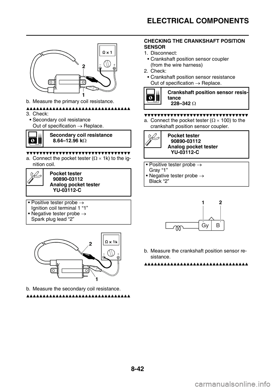
b. Measure the primary coil resistance.
▲▲▲▲▲▲▲▲▲▲▲▲▲▲▲▲▲▲▲▲▲▲▲▲▲▲▲▲▲▲▲▲
3. Check:
• Secondary coil resistance
Out of specification Replace.
▼▼▼▼▼▼▼▼▼▼▼▼▼▼▼▼▼▼▼▼▼▼▼▼▼▼▼▼▼▼▼▼
a. Connect the pocket tester ( 1k) to the ig-
nition coil.
b. Measure the secondary coil resistance.
▲▲▲▲▲▲▲▲▲▲▲▲▲▲▲▲▲▲▲▲▲▲▲▲▲▲▲▲▲▲▲▲EAS1SM1339
CHECKING THE CRANKSHAFT POSITION
SENSOR
1. Disconnect:
• Crankshaft position sensor coupler
(from the wire harness)
2. Check:
• Crankshaft position sensor resistance
Out of specification Replace.
▼▼▼▼▼▼▼▼▼▼▼▼▼▼▼▼▼▼▼▼▼▼▼▼▼▼▼▼▼▼▼▼
a. Connect the pocket tester ( 100) to the
crankshaft position sensor coupler.
b. Measure the crankshaft position sensor re-
sistance.
▲▲▲▲▲▲▲▲▲▲▲▲▲▲▲▲▲▲▲▲▲▲▲▲▲▲▲▲▲▲▲▲EAS1SM1340
Secondary coil resistance
8.64–12.96 k
Pocket tester
90890-03112
Analog pocket tester
YU-03112-C
• Positive tester probe
Ignition coil terminal 1 “1”
• Negative tester probe
Spark plug lead “2”
Crankshaft position sensor resis-
tance
228–342
Pocket tester
90890-03112
Analog pocket tester
YU-03112-C
• Positive tester probe
Gray “1”
• Negative tester probe
Black “2”
12
Gy B
Page 329 of 356
ELECTRICAL COMPONENTS
8-43
CHECKING THE ECU
1. Check:
• Mounted condition of ECU.
Improperly mounted Remount.
TIP
• The lean angle sensor is built into the ECU.
• The lean angle sensor stops the engine in
case of a turnover.
• To ensure that the lean angle sensor operates
correctly, do not change the installed condi-
tion of the ECU.
EAS1SM1341CHECKING THE STATOR COIL
1. Disconnect:
• Stator coil coupler
(from the wire harness)
2. Check:
• Stator coil resistance
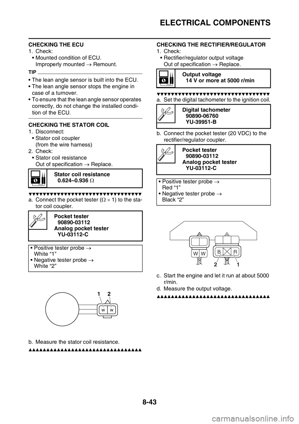
Out of specification Replace.
▼▼▼▼▼▼▼▼▼▼▼▼▼▼▼▼▼▼▼▼▼▼▼▼▼▼▼▼▼▼▼▼
a. Connect the pocket tester ( 1) to the sta-
tor coil coupler.
b. Measure the stator coil resistance.
▲▲▲▲▲▲▲▲▲▲▲▲▲▲▲▲▲▲▲▲▲▲▲▲▲▲▲▲▲▲▲▲EAS1SM1342
CHECKING THE RECTIFIER/REGULATOR
1. Check:
• Rectifier/regulator output voltage
Out of specification Replace.
▼▼▼▼▼▼▼▼▼▼▼▼▼▼▼▼▼▼▼▼▼▼▼▼▼▼▼▼▼▼▼▼
a. Set the digital tachometer to the ignition coil.
b. Connect the pocket tester (20 VDC) to the
rectifier/regulator coupler.
c. Start the engine and let it run at about 5000
r/min.
d. Measure the output voltage.
▲▲▲▲▲▲▲▲▲▲▲▲▲▲▲▲▲▲▲▲▲▲▲▲▲▲▲▲▲▲▲▲EAS1SM1343
Stator coil resistance
0.624–0.936
Pocket tester
90890-03112
Analog pocket tester
YU-03112-C
• Positive tester probe
White “1”
• Negative tester probe
White “2”
12
Output voltage
14 V or more at 5000 r/min
Digital tachometer
90890-06760
YU-39951-B
Pocket tester
90890-03112
Analog pocket tester
YU-03112-C
• Positive tester probe
Red “1”
• Negative tester probe
Black “2”
21
B
WWR
Page 330 of 356
ELECTRICAL COMPONENTS
8-44
CHECKING THE COOLANT TEMPERATURE
SENSOR
1. Remove:
• Coolant temperature sensor
EWA14130
WARNING
• Handle the coolant temperature sensor
with special care.
• Never subject the coolant temperature
sensor to strong shocks. If the coolant
temperature sensor is dropped, replace it.
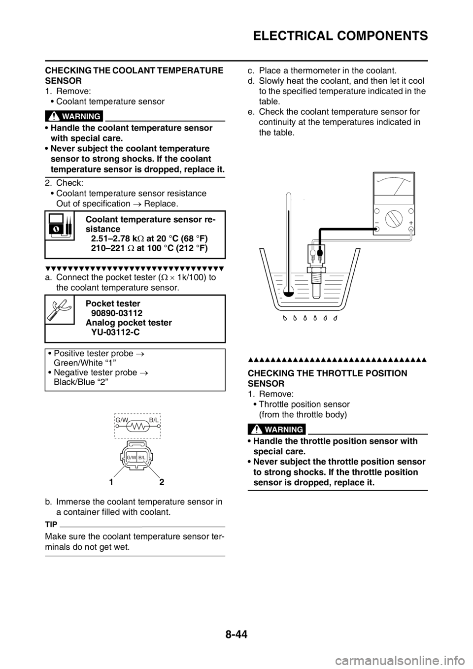
2. Check:
• Coolant temperature sensor resistance
Out of specification Replace.
▼▼▼▼▼▼▼▼▼▼▼▼▼▼▼▼▼▼▼▼▼▼▼▼▼▼▼▼▼▼▼▼
a. Connect the pocket tester ( 1k/100) to
the coolant temperature sensor.
b. Immerse the coolant temperature sensor in
a container filled with coolant.
TIP
Make sure the coolant temperature sensor ter-
minals do not get wet.c. Place a thermometer in the coolant.
d. Slowly heat the coolant, and then let it cool
to the specified temperature indicated in the
table.
e. Check the coolant temperature sensor for
continuity at the temperatures indicated in
the table.
▲▲▲▲▲▲▲▲▲▲▲▲▲▲▲▲▲▲▲▲▲▲▲▲▲▲▲▲▲▲▲▲EAS1SM1344CHECKING THE THROTTLE POSITION
SENSOR
1. Remove:
• Throttle position sensor
(from the throttle body)
EWA1DX1009
WARNING
• Handle the throttle position sensor with
special care.
• Never subject the throttle position sensor
to strong shocks. If the throttle position
sensor is dropped, replace it. Coolant temperature sensor re-
sistance
2.51–2.78 k at 20 °C (68 °F)
210–221 at 100 °C (212 °F)
Pocket tester
90890-03112
Analog pocket tester
YU-03112-C
• Positive tester probe
Green/White “1”
• Negative tester probe
Black/Blue “2”12
G/W B/L
B/L G/W
Page 331 of 356
ELECTRICAL COMPONENTS
8-45
2. Check:
• Throttle position sensor maximum resis-
tance
Out of specification Replace.
▼▼▼▼▼▼▼▼▼▼▼▼▼▼▼▼▼▼▼▼▼▼▼▼▼▼▼▼▼▼▼▼
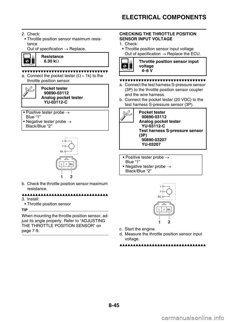
a. Connect the pocket tester ( 1k) to the
throttle position sensor.
b. Check the throttle position sensor maximum
resistance.
▲▲▲▲▲▲▲▲▲▲▲▲▲▲▲▲▲▲▲▲▲▲▲▲▲▲▲▲▲▲▲▲
3. Install:
• Throttle position sensor
TIP
When mounting the throttle position sensor, ad-
just its angle properly. Refer to “ADJUSTING
THE THROTTLE POSITION SENSOR” on
page 7-9.
EAS1SM1345
CHECKING THE THROTTLE POSITION
SENSOR INPUT VOLTAGE
1. Check:
• Throttle position sensor input voltage
Out of specification Replace the ECU.
▼▼▼▼▼▼▼▼▼▼▼▼▼▼▼▼▼▼▼▼▼▼▼▼▼▼▼▼▼▼▼▼
a. Connect the test harness S-pressure sensor
(3P) to the throttle position sensor coupler
and the wire harness.
b. Connect the pocket tester (20 VDC) to the
test harness S-pressure sensor (3P).
c. Start the engine.
d. Measure the throttle position sensor input
voltage.
▲▲▲▲▲▲▲▲▲▲▲▲▲▲▲▲▲▲▲▲▲▲▲▲▲▲▲▲▲▲▲▲EAS1SM1346
Resistance
6.30 k
Pocket tester
90890-03112
Analog pocket tester
YU-03112-C
• Positive tester probe
Blue “1”
• Negative tester probe
Black/Blue “2”
21
Throttle position sensor input
voltage
4–6 V
Pocket tester
90890-03112
Analog pocket tester
YU-03112-C
Test harness S-pressure sensor
(3P)
90890-03207
YU-03207
• Positive tester probe
Blue “1”
• Negative tester probe
Black/Blue “2”
21
Page 332 of 356
ELECTRICAL COMPONENTS
8-46
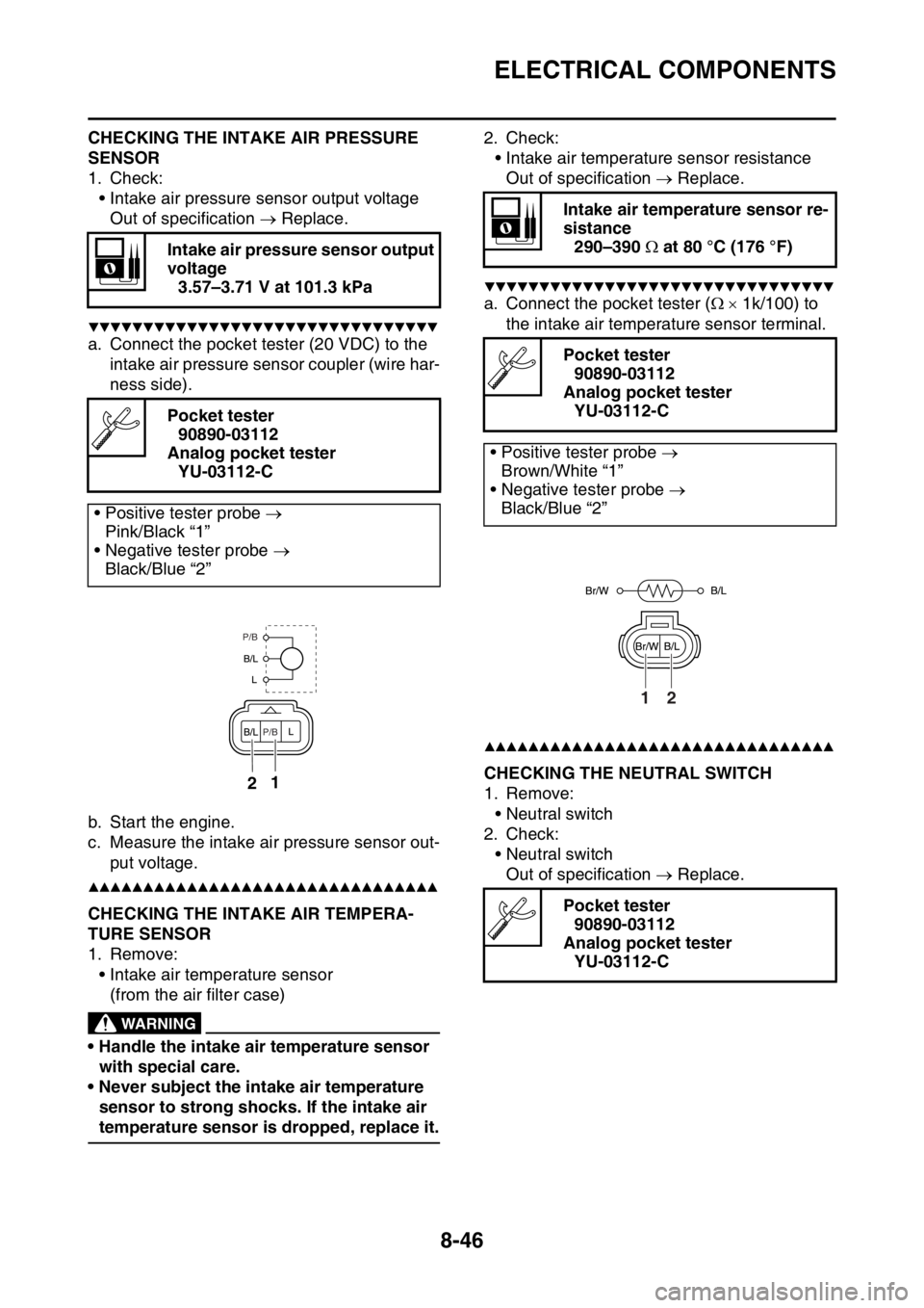
CHECKING THE INTAKE AIR PRESSURE
SENSOR
1. Check:
• Intake air pressure sensor output voltage
Out of specification Replace.
▼▼▼▼▼▼▼▼▼▼▼▼▼▼▼▼▼▼▼▼▼▼▼▼▼▼▼▼▼▼▼▼
a. Connect the pocket tester (20 VDC) to the
intake air pressure sensor coupler (wire har-
ness side).
b. Start the engine.
c. Measure the intake air pressure sensor out-
put voltage.
▲▲▲▲▲▲▲▲▲▲▲▲▲▲▲▲▲▲▲▲▲▲▲▲▲▲▲▲▲▲▲▲EAS1SM1347CHECKING THE INTAKE AIR TEMPERA-
TURE SENSOR
1. Remove:
• Intake air temperature sensor
(from the air filter case)
EWA1DX1010
WARNING
• Handle the intake air temperature sensor
with special care.
• Never subject the intake air temperature
sensor to strong shocks. If the intake air
temperature sensor is dropped, replace it.2. Check:
• Intake air temperature sensor resistance
Out of specification Replace.
▼▼▼▼▼▼▼▼▼▼▼▼▼▼▼▼▼▼▼▼▼▼▼▼▼▼▼▼▼▼▼▼
a. Connect the pocket tester ( 1k/100) to
the intake air temperature sensor terminal.
▲▲▲▲▲▲▲▲▲▲▲▲▲▲▲▲▲▲▲▲▲▲▲▲▲▲▲▲▲▲▲▲EAS1SM1348CHECKING THE NEUTRAL SWITCH
1. Remove:
• Neutral switch
2. Check:
• Neutral switch
Out of specification Replace. Intake air pressure sensor output
voltage
3.57–3.71 V at 101.3 kPa
Pocket tester
90890-03112
Analog pocket tester
YU-03112-C
• Positive tester probe
Pink/Black “1”
• Negative tester probe
Black/Blue “2”12
P/B
P/B
Intake air temperature sensor re-
sistance
290–390 at 80 °C (176 °F)
Pocket tester
90890-03112
Analog pocket tester
YU-03112-C
• Positive tester probe
Brown/White “1”
• Negative tester probe
Black/Blue “2”
Pocket tester
90890-03112
Analog pocket tester
YU-03112-C
12
Page 333 of 356
ELECTRICAL COMPONENTS
8-47
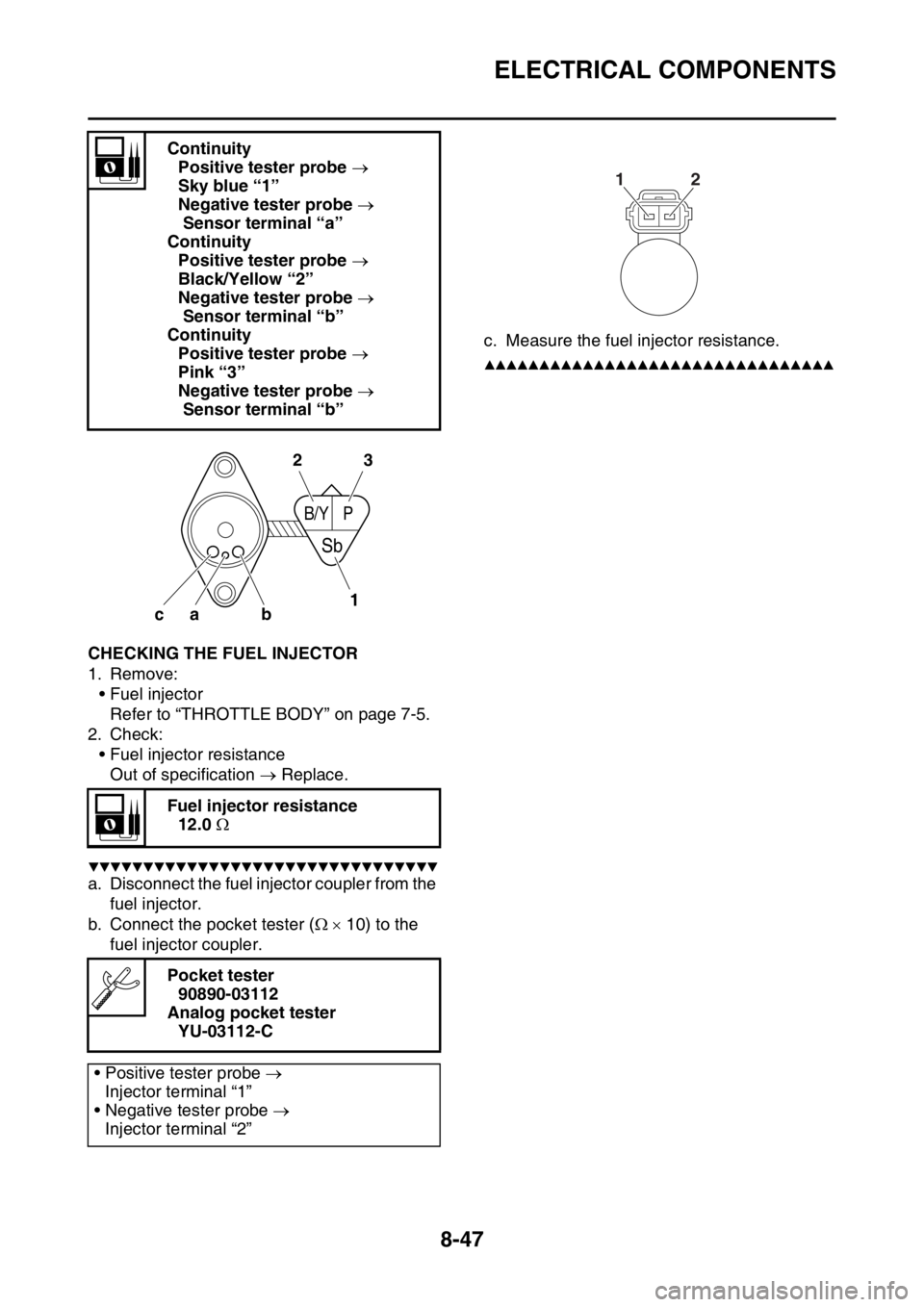
EAS1SM1349CHECKING THE FUEL INJECTOR
1. Remove:
• Fuel injector
Refer to “THROTTLE BODY” on page 7-5.
2. Check:
• Fuel injector resistance
Out of specification Replace.
▼▼▼▼▼▼▼▼▼▼▼▼▼▼▼▼▼▼▼▼▼▼▼▼▼▼▼▼▼▼▼▼
a. Disconnect the fuel injector coupler from the
fuel injector.
b. Connect the pocket tester ( 10) to the
fuel injector coupler.c. Measure the fuel injector resistance.
▲▲▲▲▲▲▲▲▲▲▲▲▲▲▲▲▲▲▲▲▲▲▲▲▲▲▲▲▲▲▲▲
Continuity
Positive tester probe
Sky blue “1”
Negative tester probe
Sensor terminal “a”
Continuity
Positive tester probe
Black/Yellow “2”
Negative tester probe
Sensor terminal “b”
Continuity
Positive tester probe
Pink “3”
Negative tester probe
Sensor terminal “b”
Fuel injector resistance
12.0
Pocket tester
90890-03112
Analog pocket tester
YU-03112-C
• Positive tester probe
Injector terminal “1”
• Negative tester probe
Injector terminal “2”
b ca
B/YP
Sb
2
13
12