wheel YAMAHA YZ250F 2014 Owners Manual
[x] Cancel search | Manufacturer: YAMAHA, Model Year: 2014, Model line: YZ250F, Model: YAMAHA YZ250F 2014Pages: 356, PDF Size: 11.39 MB
Page 9 of 356
EAS1SM1007
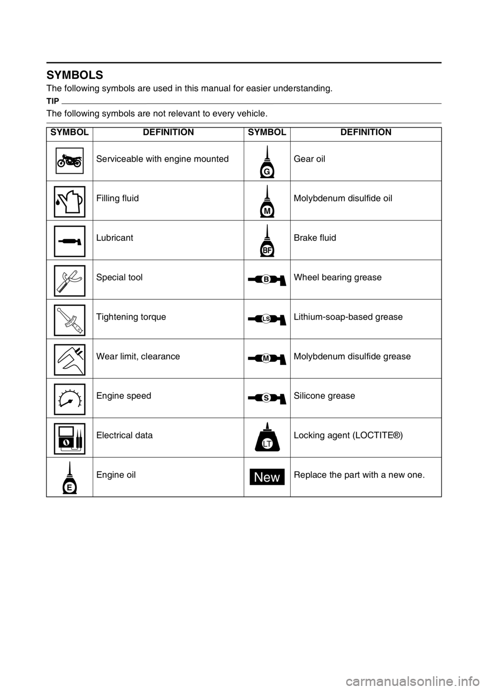
SYMBOLS
The following symbols are used in this manual for easier understanding.
TIP
The following symbols are not relevant to every vehicle.
SYMBOL DEFINITION SYMBOL DEFINITION
Serviceable with engine mounted Gear oil
Filling fluid Molybdenum disulfide oil
Lubricant Brake fluid
Special tool Wheel bearing grease
Tightening torque Lithium-soap-based grease
Wear limit, clearance Molybdenum disulfide grease
Engine speed Silicone grease
Electrical data Locking agent (LOCTITE®)
Engine oil Replace the part with a new one.
G
M
BF
B
T R..
LS
M
S
LT
E
New
Page 38 of 356
MAINTENANCE AFTER BREAK-IN
1-24
EAS1SM1046
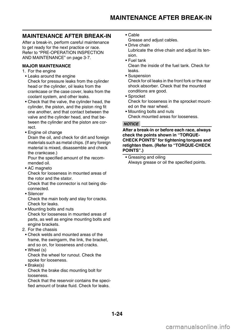
MAINTENANCE AFTER BREAK-IN
After a break-in, perform careful maintenance
to get ready for the next practice or race.
Refer to “PRE-OPERATION INSPECTION
AND MAINTENANCE” on page 3-7.
EAS1SM1047MAJOR MAINTENANCE
1. For the engine
• Leaks around the engine
Check for pressure leaks from the cylinder
head or the cylinder, oil leaks from the
crankcase or the case cover, leaks from the
coolant system, and other leaks.
• Check that the valve, the cylinder head, the
cylinder, the piston, and the piston ring fit
one another, and that contact between the
valve and the cylinder head, and that be-
tween the cylinder and the piston are cor-
rect.
• Engine oil change
Drain the oil, and check for dirt and foreign
materials such as metal chips. (If any foreign
material is mixed, disassemble and check
the crankcase.)
Pour the specified amount of the recom-
mended oil.
• AC magneto
Check for looseness in mounted areas of
the rotor and the stator.
Check that the connector is not being dis-
connected.
• Silencer
Check the main body and stay for cracks.
Check for leaks.
• Mounting bolts and nuts
Check for looseness in mounted areas of
parts, as well as engine mounting bolts and
engine brackets.
2. For the chassis
• Check welds and mounted areas of the
frame, the swingarm, the link, the bracket,
and so on, for looseness and cracks.
• Wheel (s)
Check the wheel for runout. Check the
spoke for looseness.
• Brake(s)
Check the brake disc mounting bolt for
looseness.
Check that the reservoir contains the speci-
fied amount of brake fluid. Check for leaks.• Cable
Grease and adjust cables.
•Drive chain
Lubricate the drive chain and adjust its ten-
sion.
• Fuel tank
Clean the inside of the fuel tank. Check for
leaks.
• Suspension
Check for oil leaks in the front fork or the rear
shock absorber. Check that the mounted
conditions are good.
• Sprocket
Check for looseness in the sprocket mount-
ed on the rear wheel.
• Mounting bolts and nuts
Check mounted areas for looseness.
JCA1SL1001
NOTICE
After a break-in or before each race, always
check the points shown in “TORQUE-
CHECK POINTS” for tightening torques and
retighten them. (Refer to “TORQUE-CHECK
POINTS”.)
• Greasing and oiling
Always grease or oil the specified points.
Page 39 of 356

TORQUE-CHECK POINTS
1-25
EAS1SM1048
TORQUE-CHECK POINTS
Frame construction Frame to rear frame
Frame to engine protector
Combined seat and fuel tank Fuel tank to frame
Engine mounting Frame to engine
Engine bracket to engine
Engine bracket to frame
Seat Seat to frame
Steering Steering stem to handlebar Steering stem to frame
Steering stem to upper bracket
Upper bracket to handlebar
Suspension Front Steering stem to front fork Front fork to upper bracket
Front fork to lower bracket
Rear Link Assembly of links
Link to frame
Link to rear shock absorber
Link to swingarm
Mounting of rear shock absorber Rear shock absorber and frame
Mounting of swingarm Tightening of pivot shaft
Wheel (s) Mounting of wheel Front Tightening of wheel axle
Tightening of axle holder
Tightening of spoke nipple
Rear Tightening of wheel axle
Wheel to rear wheel sprocket
Tightening of spoke nipple
Brake(s) Front Brake caliper to front fork
Brake disc to wheel
Tightening of union bolt
Brake master cylinder to handle-
bar
Tightening of bleed screw
Tightening of brake hose holder
Rear Brake pedal to frame
Brake disc to wheel
Tightening of union bolt
Brake master cylinder to frame
Tightening of bleed screw
Tightening of brake hose holder
Shift pedal Shift pedal to shift shaft
Fuel system Fuel pump to fuel tank
Page 41 of 356
CLEANING AND STORAGE
1-27
EAS1SM1049
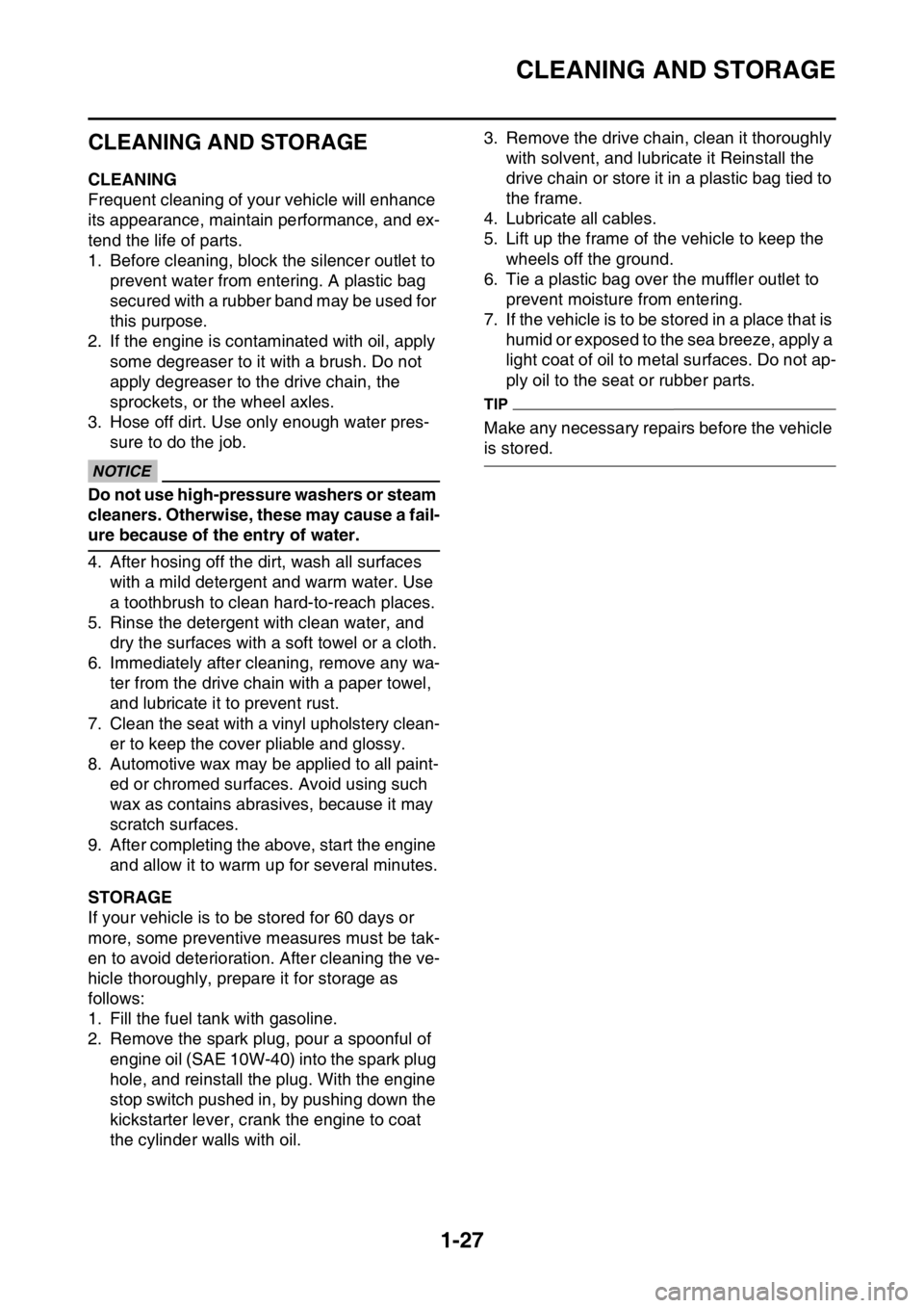
CLEANING AND STORAGE
EAS1SM1050CLEANING
Frequent cleaning of your vehicle will enhance
its appearance, maintain performance, and ex-
tend the life of parts.
1. Before cleaning, block the silencer outlet to
prevent water from entering. A plastic bag
secured with a rubber band may be used for
this purpose.
2. If the engine is contaminated with oil, apply
some degreaser to it with a brush. Do not
apply degreaser to the drive chain, the
sprockets, or the wheel axles.
3. Hose off dirt. Use only enough water pres-
sure to do the job.
ECA
NOTICE
Do not use high-pressure washers or steam
cleaners. Otherwise, these may cause a fail-
ure because of the entry of water.
4. After hosing off the dirt, wash all surfaces
with a mild detergent and warm water. Use
a toothbrush to clean hard-to-reach places.
5. Rinse the detergent with clean water, and
dry the surfaces with a soft towel or a cloth.
6. Immediately after cleaning, remove any wa-
ter from the drive chain with a paper towel,
and lubricate it to prevent rust.
7. Clean the seat with a vinyl upholstery clean-
er to keep the cover pliable and glossy.
8. Automotive wax may be applied to all paint-
ed or chromed surfaces. Avoid using such
wax as contains abrasives, because it may
scratch surfaces.
9. After completing the above, start the engine
and allow it to warm up for several minutes.
EAS1SM1051STORAGE
If your vehicle is to be stored for 60 days or
more, some preventive measures must be tak-
en to avoid deterioration. After cleaning the ve-
hicle thoroughly, prepare it for storage as
follows:
1. Fill the fuel tank with gasoline.
2. Remove the spark plug, pour a spoonful of
engine oil (SAE 10W-40) into the spark plug
hole, and reinstall the plug. With the engine
stop switch pushed in, by pushing down the
kickstarter lever, crank the engine to coat
the cylinder walls with oil.3. Remove the drive chain, clean it thoroughly
with solvent, and lubricate it Reinstall the
drive chain or store it in a plastic bag tied to
the frame.
4. Lubricate all cables.
5. Lift up the frame of the vehicle to keep the
wheels off the ground.
6. Tie a plastic bag over the muffler outlet to
prevent moisture from entering.
7. If the vehicle is to be stored in a place that is
humid or exposed to the sea breeze, apply a
light coat of oil to metal surfaces. Do not ap-
ply oil to the seat or rubber parts.
TIP
Make any necessary repairs before the vehicle
is stored.
Page 44 of 356

GENERAL SPECIFICATIONS
2-1
EAS1SM1052
GENERAL SPECIFICATIONS
Model
Model 1SM1 (USA) (CAN)
1SM2 (EUR)
1SM3 (JPN)
1SM4 (AUS) (NZL) (ZAF)
Dimensions
Overall length 2165 mm (85.2 in) (USA) (CAN) (AUS) (NZL)
(ZAF)
2170 mm (85.4 in) (EUR) (JPN)
Overall width 825 mm (32.5 in)
Overall height 1280 mm (50.4 in) (USA) (CAN) (EUR) (JPN)
1275 mm (50.2 in) (AUS) (NZL) (ZAF)
Seat height 965 mm (38.0 in) (USA) (CAN) (EUR) (JPN)
960 mm (37.8 in) (AUS) (NZL) (ZAF)
Wheelbase 1475 mm (58.1 in)
Ground clearance 325 mm (12.80 in) (USA) (CAN) (AUS) (NZL)
(ZAF)
330 mm (12.99 in) (EUR) (JPN)
Weight
Curb weight 105 kg (231 lb)
Page 51 of 356

CHASSIS SPECIFICATIONS
2-8
EAS1SM1054
CHASSIS SPECIFICATIONS
Chassis
Frame type Semi double cradle
Caster angle 27.08 ° (USA) (CAN) (AUS) (NZL) (ZAF)
26.83 ° (EUR)
27.00 ° (JPN)
Trail 118 mm (4.6 in) (USA) (CAN) (EUR)
119 mm (4.7 in) (JPN) (AUS) (NZL) (ZAF)
Front wheel
Wheel type Spoke wheel
Rim size 21 1.60
Rim material Aluminum
Wheel travel 310.0 mm (12.20 in)
Radial wheel runout limit 2.0 mm (0.08 in)
Lateral wheel runout limit 2.0 mm (0.08 in)
Wheel axle bending limit 0.50 mm (0.02 in)
Rear wheel
Wheel type Spoke wheel
Rim size 19 1.85
Rim material Aluminum
Wheel travel 315.0 mm (12.40 in)
Radial wheel runout limit 2.0 mm (0.08 in)
Lateral wheel runout limit 2.0 mm (0.08 in)
Wheel axle bending limit 0.50 mm (0.02 in)
Front tire
Type With tube
Size 80/100-21 51M
Manufacturer/model BRIDGESTONE/M403A (USA) (CAN) (AUS)
(NZL) (ZAF)
PIRELLI/MID SOFT 32 (EUR)
DUNLOP/MX51FA (JPN)
Rear tire
Type With tube
Size 100/90-19 57M
Manufacturer/model BRIDGESTONE/M404 (USA) (CAN) (AUS)
(NZL) (ZAF)
PIRELLI/MID SOFT 32 (EUR)
DUNLOP/MX51G (JPN)
Tire air pressure (measured on cold tires)
Front 100 kPa (1.00 kgf/cm2, 15 psi)
Rear 100 kPa (1.00 kgf/cm2, 15 psi)
Front brake
Type Single disc brake
Operation Right hand operation
Front disc brake
Disc outside diameter thickness 250.0 3.0 mm (9.84 0.12 in)
Page 57 of 356

TIGHTENING TORQUES
2-14
Air filter guide holder screw
M5 8 2.5 Nm (0.25 m·kgf, 1.8 ft·lbf)
Air filter case cap screw
M5 1 2.5 Nm (0.25 m·kgf, 1.8 ft·lbf)
Starter knob/Idle screw
M12 1 2.1 Nm (0.21 m·kgf, 1.5 ft·lbf)
Throttle cable nut (pull)
M10 1 7 Nm (0.7 m·kgf, 5.1 ft·lbf)
Throttle cable nut (return)
M10 1 7 Nm (0.7 m·kgf, 5.1 ft·lbf)
Clutch cable adjuster and locknut
M6 1 4.3 Nm (0.43 m·kgf, 3.1 ft·lbf)
Clutch cable locknut (engine side)
M8 1 7 Nm (0.7 m·kgf, 5.1 ft·lbf)
Exhaust pipe nut
M8 2 See TIP.
Exhaust pipe protector screw
M6 4 10 Nm (1.0 m·kgf, 7.2 ft·lbf)
Exhaust pipe bracket bolt
M8 1 20 Nm (2.0 m·kgf, 14 ft·lbf)
Frame and silencer bolt (front) M8 1 30 Nm (3.0 m·kgf, 22 ft·lbf)
Frame and silencer bolt (rear) M8 1 30 Nm (3.0 m·kgf, 22 ft·lbf)
Exhaust pipe clamp bolt
M8 2 12 Nm (1.2 m·kgf, 8.7 ft·lbf)
Silencer body bolt
M5 6 8 Nm (0.8 m·kgf, 5.8 ft·lbf)
Oil nozzle bolt
M5 1 5 Nm (0.5 m·kgf, 3.6 ft·lbf)
Engine oil drain bolt
M10 1 20 Nm (2.0 m·kgf, 14 ft·lbf)
Crankcase bolt
M6 12 12 Nm (1.2 m·kgf, 8.7 ft·lbf)
Clutch cable holder bolt
M6 2 10 Nm (1.0 m·kgf, 7.2 ft·lbf)
Crankshaft end accessing screw
M36 1 10 Nm (1.0 m·kgf, 7.2 ft·lbf)
Timing mark accessing screw
M14 1 6 Nm (0.6 m·kgf, 4.3 ft·lbf)
Drive chain sprocket cover bolt
M6 2 7 Nm (0.7 m·kgf, 5.1 ft·lbf)
Crankcase bearing cover plate
screwM6 6 10 Nm (1.0 m·kgf, 7.2 ft·lbf)
Crankcase bearing cover plate
screw (crankshaft)M8 4 22 Nm (2.2 m·kgf, 16 ft·lbf)
Oil passage squeeze nozzle
M8 1 3.0 Nm (0.30 m·kgf, 2.2 ft·lbf)
Clutch cover bolt
M6 7 10 Nm (1.0 m·kgf, 7.2 ft·lbf)
Left crankcase cover bolt
M6 7 10 Nm (1.0 m·kgf, 7.2 ft·lbf)
Right crankcase cover bolt
M6 11 10 Nm (1.0 m·kgf, 7.2 ft·lbf)
Oil filter element cover bolt
M6 2 10 Nm (1.0 m·kgf, 7.2 ft·lbf)
Kick shaft ratchet wheel guide
boltM6 2 12 Nm (1.2 m·kgf, 8.7 ft·lbf)
Kick starter lever bolt
M8 1 33 Nm (3.3 m·kgf, 24 ft·lbf)
Kick starter lever boss screw
M6 1 7 Nm (0.7 m·kgf, 5.1 ft·lbf)
Primary drive gear nut
M16 1 75 Nm (7.5 m·kgf, 54 ft·lbf)
Clutch spring bolt
M6 5 10 Nm (1.0 m·kgf, 7.2 ft·lbf)
Clutch boss nut M16 1 75 Nm (7.5 m·kgf, 54 ft·lbf)Use a lock
washer. ITEMThread
sizeQ’ty TIGHTENING TORQUES Remarks
LT
LT
LT
LT
LT
LT
LT
LT
Page 59 of 356
TIGHTENING TORQUES
2-16
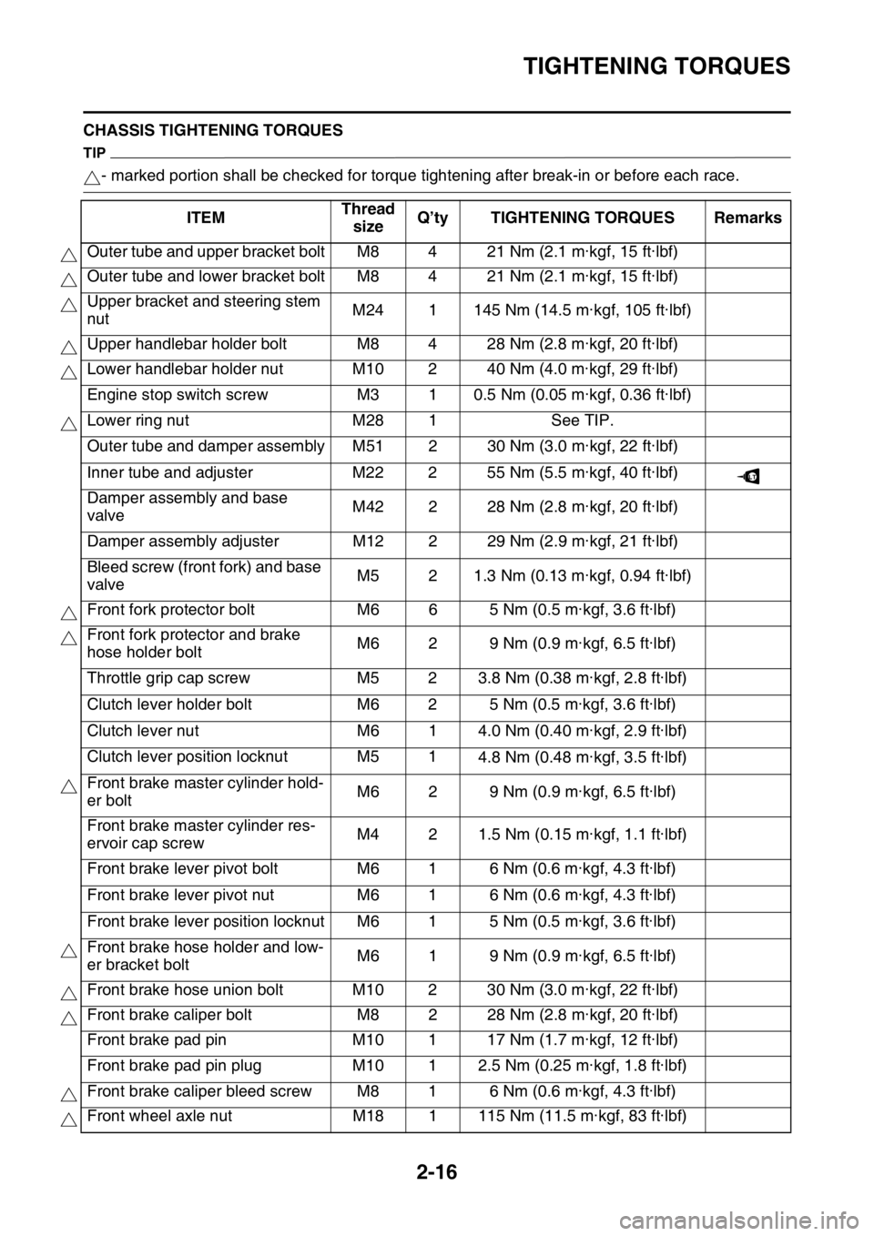
CHASSIS TIGHTENING TORQUES
TIP
- marked portion shall be checked for torque tightening after break-in or before each race.
ITEMThread
sizeQ’ty TIGHTENING TORQUES Remarks
Outer tube and upper bracket bolt M8 4 21 Nm (2.1 m·kgf, 15 ft·lbf)
Outer tube and lower bracket bolt M8 4 21 Nm (2.1 m·kgf, 15 ft·lbf)
Upper bracket and steering stem
nutM24 1 145 Nm (14.5 m·kgf, 105 ft·lbf)
Upper handlebar holder bolt M8 4 28 Nm (2.8 m·kgf, 20 ft·lbf)
Lower handlebar holder nut M10 2 40 Nm (4.0 m·kgf, 29 ft·lbf)
Engine stop switch screw M3 1 0.5 Nm (0.05 m·kgf, 0.36 ft·lbf)
Lower ring nut M28 1 See TIP.
Outer tube and damper assembly M51 2 30 Nm (3.0 m·kgf, 22 ft·lbf)
Inner tube and adjuster M22 2 55 Nm (5.5 m·kgf, 40 ft·lbf)
Damper assembly and base
valveM42 2 28 Nm (2.8 m·kgf, 20 ft·lbf)
Damper assembly adjuster M12 2 29 Nm (2.9 m·kgf, 21 ft·lbf)
Bleed screw (front fork) and base
valveM5 2 1.3 Nm (0.13 m·kgf, 0.94 ft·lbf)
Front fork protector bolt M6 6 5 Nm (0.5 m·kgf, 3.6 ft·lbf)
Front fork protector and brake
hose holder boltM6 2 9 Nm (0.9 m·kgf, 6.5 ft·lbf)
Throttle grip cap screw M5 2 3.8 Nm (0.38 m·kgf, 2.8 ft·lbf)
Clutch lever holder bolt M6 2 5 Nm (0.5 m·kgf, 3.6 ft·lbf)
Clutch lever nut M6 1 4.0 Nm (0.40 m·kgf, 2.9 ft·lbf)
Clutch lever position locknut M5 1
4.8 Nm (0.48 m·kgf, 3.5 ft·lbf)
Front brake master cylinder hold-
er boltM6 2 9 Nm (0.9 m·kgf, 6.5 ft·lbf)
Front brake master cylinder res-
ervoir cap screwM4 2 1.5 Nm (0.15 m·kgf, 1.1 ft·lbf)
Front brake lever pivot bolt M6 1 6 Nm (0.6 m·kgf, 4.3 ft·lbf)
Front brake lever pivot nut M6 1 6 Nm (0.6 m·kgf, 4.3 ft·lbf)
Front brake lever position locknut M6 1 5 Nm (0.5 m·kgf, 3.6 ft·lbf)
Front brake hose holder and low-
er bracket boltM6 1 9 Nm (0.9 m·kgf, 6.5 ft·lbf)
Front brake hose union bolt M10 2 30 Nm (3.0 m·kgf, 22 ft·lbf)
Front brake caliper bolt M8 2 28 Nm (2.8 m·kgf, 20 ft·lbf)
Front brake pad pin M10 1 17 Nm (1.7 m·kgf, 12 ft·lbf)
Front brake pad pin plug M10 1 2.5 Nm (0.25 m·kgf, 1.8 ft·lbf)
Front brake caliper bleed screw M8 1 6 Nm (0.6 m·kgf, 4.3 ft·lbf)
Front wheel axle nut M18 1 115 Nm (11.5 m·kgf, 83 ft·lbf)
LT
Page 60 of 356
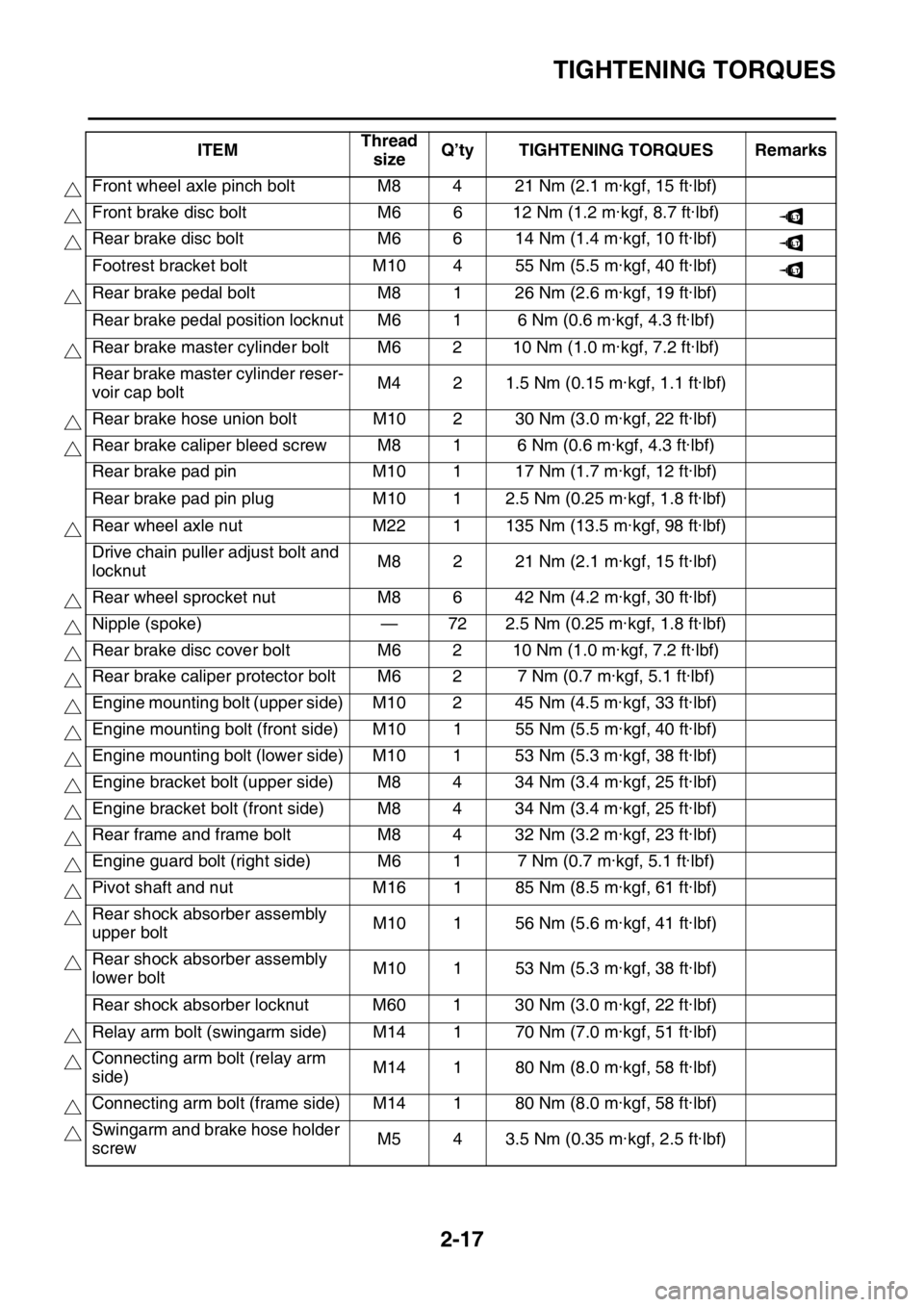
TIGHTENING TORQUES
2-17
Front wheel axle pinch bolt M8 4 21 Nm (2.1 m·kgf, 15 ft·lbf)
Front brake disc bolt M6 6 12 Nm (1.2 m·kgf, 8.7 ft·lbf)
Rear brake disc bolt M6 6 14 Nm (1.4 m·kgf, 10 ft·lbf)
Footrest bracket bolt M10 4 55 Nm (5.5 m·kgf, 40 ft·lbf)
Rear brake pedal bolt M8 1 26 Nm (2.6 m·kgf, 19 ft·lbf)
Rear brake pedal position locknut M6 1 6 Nm (0.6 m·kgf, 4.3 ft·lbf)
Rear brake master cylinder bolt M6 2 10 Nm (1.0 m·kgf, 7.2 ft·lbf)
Rear brake master cylinder reser-
voir cap boltM4 2 1.5 Nm (0.15 m·kgf, 1.1 ft·lbf)
Rear brake hose union bolt M10 2 30 Nm (3.0 m·kgf, 22 ft·lbf)
Rear brake caliper bleed screw M8 1 6 Nm (0.6 m·kgf, 4.3 ft·lbf)
Rear brake pad pin M10 1 17 Nm (1.7 m·kgf, 12 ft·lbf)
Rear brake pad pin plug M10 1 2.5 Nm (0.25 m·kgf, 1.8 ft·lbf)
Rear wheel axle nut M22 1 135 Nm (13.5 m·kgf, 98 ft·lbf)
Drive chain puller adjust bolt and
locknutM8 2 21 Nm (2.1 m·kgf, 15 ft·lbf)
Rear wheel sprocket nut M8 6 42 Nm (4.2 m·kgf, 30 ft·lbf)
Nipple (spoke) — 72 2.5 Nm (0.25 m·kgf, 1.8 ft·lbf)
Rear brake disc cover bolt M6 2 10 Nm (1.0 m·kgf, 7.2 ft·lbf)
Rear brake caliper protector bolt M6 2 7 Nm (0.7 m·kgf, 5.1 ft·lbf)
Engine mounting bolt (upper side) M10 2 45 Nm (4.5 m·kgf, 33 ft·lbf)
Engine mounting bolt (front side) M10 1 55 Nm (5.5 m·kgf, 40 ft·lbf)
Engine mounting bolt (lower side) M10 1 53 Nm (5.3 m·kgf, 38 ft·lbf)
Engine bracket bolt (upper side) M8 4 34 Nm (3.4 m·kgf, 25 ft·lbf)
Engine bracket bolt (front side) M8 4 34 Nm (3.4 m·kgf, 25 ft·lbf)
Rear frame and frame bolt M8 4 32 Nm (3.2 m·kgf, 23 ft·lbf)
Engine guard bolt (right side) M6 1 7 Nm (0.7 m·kgf, 5.1 ft·lbf)
Pivot shaft and nut M16 1 85 Nm (8.5 m·kgf, 61 ft·lbf)
Rear shock absorber assembly
upper boltM10 1 56 Nm (5.6 m·kgf, 41 ft·lbf)
Rear shock absorber assembly
lower boltM10 1 53 Nm (5.3 m·kgf, 38 ft·lbf)
Rear shock absorber locknut M60 1 30 Nm (3.0 m·kgf, 22 ft·lbf)
Relay arm bolt (swingarm side) M14 1 70 Nm (7.0 m·kgf, 51 ft·lbf)
Connecting arm bolt (relay arm
side)M14 1 80 Nm (8.0 m·kgf, 58 ft·lbf)
Connecting arm bolt (frame side) M14 1 80 Nm (8.0 m·kgf, 58 ft·lbf)
Swingarm and brake hose holder
screwM5 4 3.5 Nm (0.35 m·kgf, 2.5 ft·lbf) ITEMThread
sizeQ’ty TIGHTENING TORQUES Remarks
LT
LT
LT
Page 62 of 356
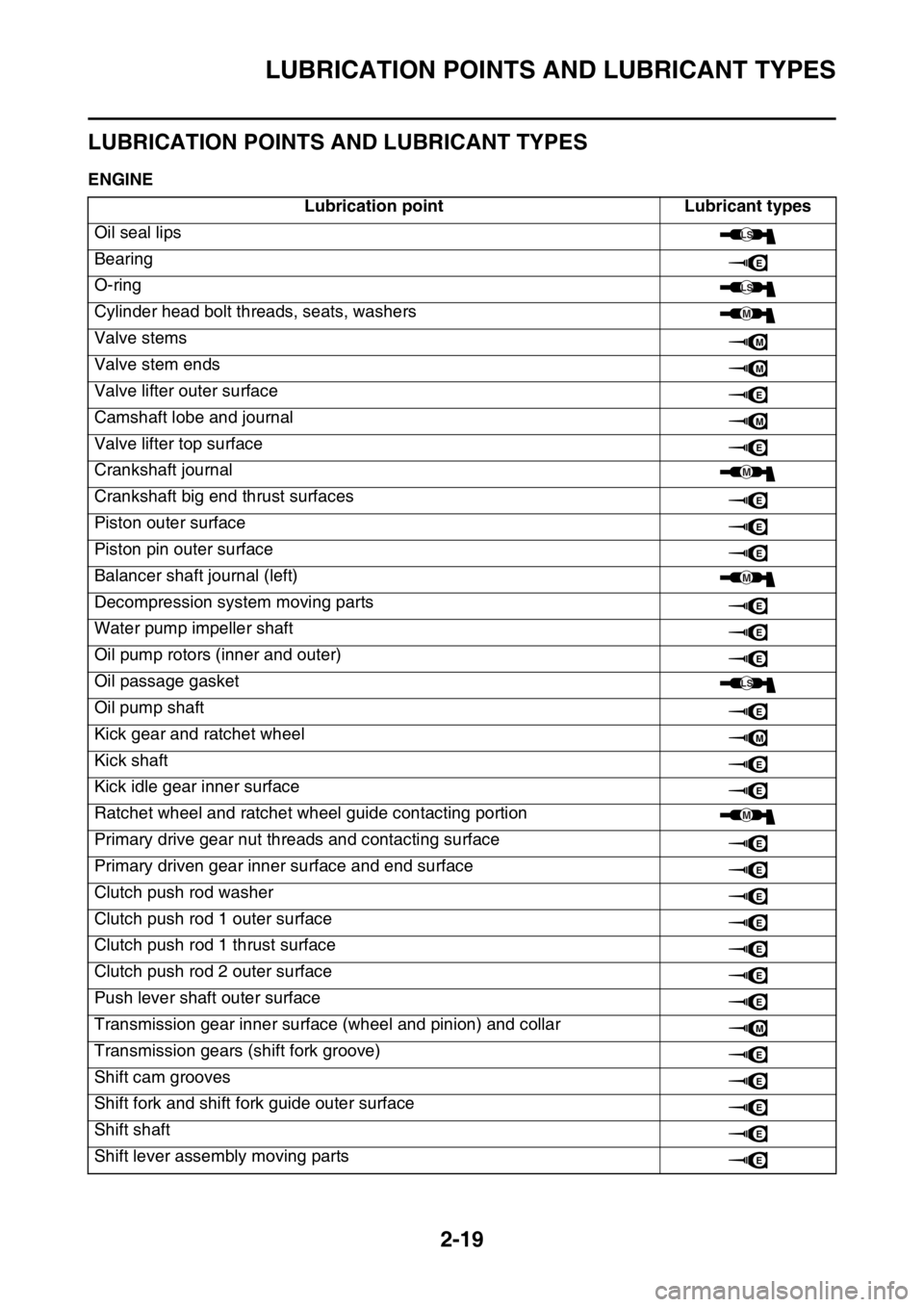
LUBRICATION POINTS AND LUBRICANT TYPES
2-19
EAS1SM1059
LUBRICATION POINTS AND LUBRICANT TYPES
EAS1SM1060ENGINE
Lubrication point Lubricant types
Oil seal lips
Bearing
O-ring
Cylinder head bolt threads, seats, washers
Valve stems
Valve stem ends
Valve lifter outer surface
Camshaft lobe and journal
Valve lifter top surface
Crankshaft journal
Crankshaft big end thrust surfaces
Piston outer surface
Piston pin outer surface
Balancer shaft journal (left)
Decompression system moving parts
Water pump impeller shaft
Oil pump rotors (inner and outer)
Oil passage gasket
Oil pump shaft
Kick gear and ratchet wheel
Kick shaft
Kick idle gear inner surface
Ratchet wheel and ratchet wheel guide contacting portion
Primary drive gear nut threads and contacting surface
Primary driven gear inner surface and end surface
Clutch push rod washer
Clutch push rod 1 outer surface
Clutch push rod 1 thrust surface
Clutch push rod 2 outer surface
Push lever shaft outer surface
Transmission gear inner surface (wheel and pinion) and collar
Transmission gears (shift fork groove)
Shift cam grooves
Shift fork and shift fork guide outer surface
Shift shaft
Shift lever assembly moving parts
LS
E
LS
M
M
M
E
M
E
M
E
E
E
M
E
E
E
LS
E
M
E
E
M
E
E
E
E
E
E
E
M
E
E
E
E
E