fuel pump YAMAHA YZ250F 2015 Owners Manual
[x] Cancel search | Manufacturer: YAMAHA, Model Year: 2015, Model line: YZ250F, Model: YAMAHA YZ250F 2015Pages: 356, PDF Size: 11.39 MB
Page 20 of 356
FEATURES
1-6
EAS20170
FEATURES
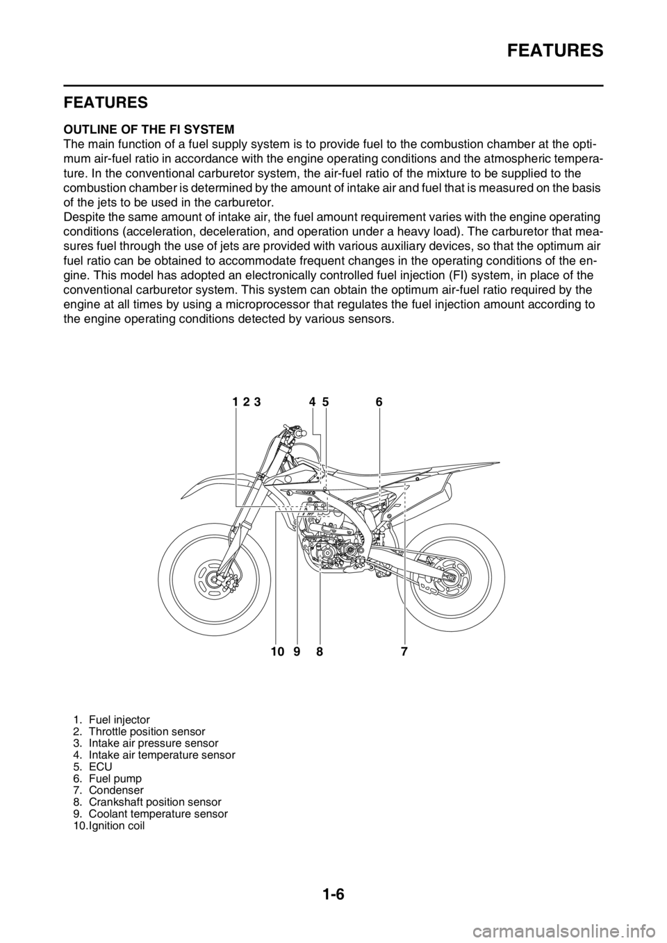
EAS1SM5014OUTLINE OF THE FI SYSTEM
The main function of a fuel supply system is to provide fuel to the combustion chamber at the opti-
mum air-fuel ratio in accordance with the engine operating conditions and the atmospheric tempera-
ture. In the conventional carburetor system, the air-fuel ratio of the mixture to be supplied to the
combustion chamber is determined by the amount of intake air and fuel that is measured on the basis
of the jets to be used in the carburetor.
Despite the same amount of intake air, the fuel amount requirement varies with the engine operating
conditions (acceleration, deceleration, and operation under a heavy load). The carburetor that mea-
sures fuel through the use of jets are provided with various auxiliary devices, so that the optimum air
fuel ratio can be obtained to accommodate frequent changes in the operating conditions of the en-
gine. This model has adopted an electronically controlled fuel injection (FI) system, in place of the
conventional carburetor system. This system can obtain the optimum air-fuel ratio required by the
engine at all times by using a microprocessor that regulates the fuel injection amount according to
the engine operating conditions detected by various sensors.
1. Fuel injector
2. Throttle position sensor
3. Intake air pressure sensor
4. Intake air temperature sensor
5. ECU
6. Fuel pump
7. Condenser
8. Crankshaft position sensor
9. Coolant temperature sensor
10.Ignition coil
6
7 8 95 4 123
10
Page 21 of 356
FEATURES
1-7
EAS1SM5015FI SYSTEM
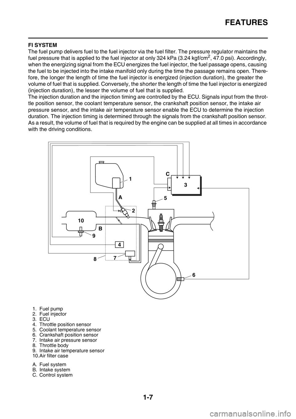
The fuel pump delivers fuel to the fuel injector via the fuel filter. The pressure regulator maintains the
fuel pressure that is applied to the fuel injector at only 324 kPa (3.24 kgf/cm
2, 47.0 psi). Accordingly,
when the energizing signal from the ECU energizes the fuel injector, the fuel passage opens, causing
the fuel to be injected into the intake manifold only during the time the passage remains open. There-
fore, the longer the length of time the fuel injector is energized (injection duration), the greater the
volume of fuel that is supplied. Conversely, the shorter the length of time the fuel injector is energized
(injection duration), the lesser the volume of fuel that is supplied.
The injection duration and the injection timing are controlled by the ECU. Signals input from the throt-
tle position sensor, the coolant temperature sensor, the crankshaft position sensor, the intake air
pressure sensor, and the intake air temperature sensor enable the ECU to determine the injection
duration. The injection timing is determined through the signals from the crankshaft position sensor.
As a result, the volume of fuel that is required by the engine can be supplied at all times in accordance
with the driving conditions.
1. Fuel pump
2. Fuel injector
3. ECU
4. Throttle position sensor
5. Coolant temperature sensor
6. Crankshaft position sensor
7. Intake air pressure sensor
8. Throttle body
9. Intake air temperature sensor
10.Air filter case
A. Fuel system
B. Intake system
C. Control system
1
23
5
6 7
8 9 10A
BC
4
Page 36 of 356
STARTING AND BREAK-IN
1-22
EAS1SM5042
STARTING AND BREAK-IN
EAS1SM5043FUEL
Always use the recommended fuel as stated
below. Also, be sure to use new gasoline the
day of a race.
JCA
NOTICE
Use only unleaded gasoline. The use of
leaded gasoline will cause severe damage
to the engine internal parts such as valves,
piston rings, and exhaust system, etc.
TIP
Your Yamaha engine has been designed to use
premium unleaded gasoline with a pump oc-
tane number [(R+M)/2] of 91 or higher, or a re-
search octane number of 95 or higher. If
knocking (or pinging) occurs, use a gasoline of
a different brand.
JWA
WARNING
• For refueling, be sure to stop the engine
and use enough care not to spill any fuel.
Also be sure to avoid refueling close to a
fire.
• Refuel after the engine, exhaust pipe, etc.
have cooled off.
Gasohol (For USA and Canada)
There are two types of gasohol: gasohol con-
taining ethanol and that containing methanol.
Gasohol containing ethanol can be used if the
ethanol content does not exceed 10%. Gasohol
containing methanol is not recommended by
Yamaha because it can cause damage to the
fuel system or vehicle performance problems.
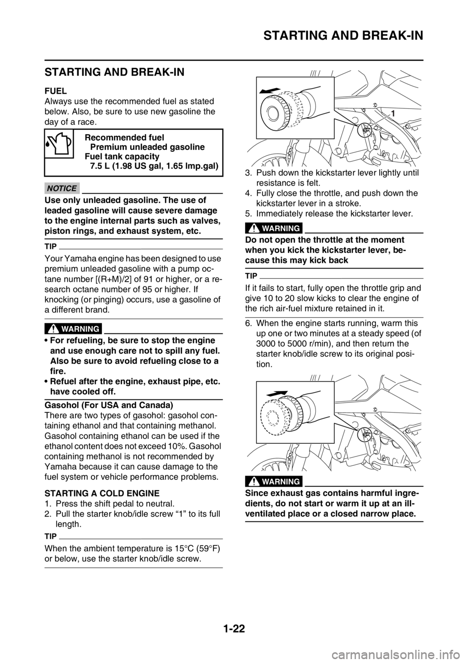
EAS1SM5044STARTING A COLD ENGINE
1. Press the shift pedal to neutral.
2. Pull the starter knob/idle screw “1” to its full
length.
TIP
When the ambient temperature is 15°C (59°F)
or below, use the starter knob/idle screw.3. Push down the kickstarter lever lightly until
resistance is felt.
4. Fully close the throttle, and push down the
kickstarter lever in a stroke.
5. Immediately release the kickstarter lever.
EWA
WARNING
Do not open the throttle at the moment
when you kick the kickstarter lever, be-
cause this may kick back
TIP
If it fails to start, fully open the throttle grip and
give 10 to 20 slow kicks to clear the engine of
the rich air-fuel mixture retained in it.
6. When the engine starts running, warm this
up one or two minutes at a steady speed (of
3000 to 5000 r/min), and then return the
starter knob/idle screw to its original posi-
tion.
EWA
WARNING
Since exhaust gas contains harmful ingre-
dients, do not start or warm it up at an ill-
ventilated place or a closed narrow place. Recommended fuel
Premium unleaded gasoline
Fuel tank capacity
7.5 L (1.98 US gal, 1.65 lmp.gal)
1
Page 39 of 356

TORQUE-CHECK POINTS
1-25
EAS1SM5049
TORQUE-CHECK POINTS
Frame construction Frame to rear frame
Frame to engine protector
Combined seat and fuel tank Fuel tank to frame
Engine mounting Frame to engine
Engine bracket to engine
Engine bracket to frame
Seat Seat to frame
Steering Steering stem to handlebar Steering stem to frame
Steering stem to upper bracket
Upper bracket to handlebar
Suspension Front Steering stem to front fork Front fork to upper bracket
Front fork to lower bracket
Rear Link Assembly of links
Link to frame
Link to rear shock absorber
Link to swingarm
Mounting of rear shock absorber Rear shock absorber and frame
Mounting of swingarm Tightening of pivot shaft
Wheel (s) Mounting of wheel Front Tightening of wheel axle
Tightening of axle holder
Tightening of spoke nipple
Rear Tightening of wheel axle
Wheel to rear wheel sprocket
Tightening of spoke nipple
Brake(s) Front Brake caliper to front fork
Brake disc to wheel
Tightening of union bolt
Brake master cylinder to handle-
bar
Tightening of bleed screw
Tightening of brake hose holder
Rear Brake pedal to frame
Brake disc to wheel
Tightening of union bolt
Brake master cylinder to frame
Tightening of bleed screw
Tightening of brake hose holder
Shift pedal Shift pedal to shift shaft
Fuel system Fuel pump to fuel tank
Page 45 of 356

ENGINE SPECIFICATIONS
2-2
EAS1SM5054
ENGINE SPECIFICATIONS
Engine
Engine type Liquid cooled 4-stroke, DOHC
Displacement 250 cm
3
Cylinder arrangement Single cylinder
Bore stroke 77.0 53.6 mm (3.0 2.1 in)
Compression ratio 13.5:1
Starting system Kickstarter
Fuel
Recommended fuel Premium unleaded gasoline only
Fuel tank capacity 7.5 L (1.98 US gal, 1.65 Imp.gal)
Engine oil
Lubrication system Wet sump
Recommended brand YAMALUBE
Type SAE 10W-30, SAE 10W-40, SAE 10W-50,
SAE 15W-40, SAE 20W-40 or SAE 20W-50
Recommended oil grade API service SG type or higher, JASO standard
MA
Engine oil quantity
Quantity (disassembled) 0.90 L (0.95 US qt, 0.79 Imp.qt)
With oil filter element replacement 0.73 L (0.77 US qt, 0.64 Imp.qt)
Without oil filter element replacement 0.71 L (0.75 US qt, 0.62 Imp.qt)
Oil filter
Oil filter type Paper
Oil pump
Oil pump type Trochoid
Inner-rotor-to-outer-rotor-tip clearance Less than 0.150 mm (0.0059 in)
Limit 0.20 mm (0.0079 in)
Outer-rotor-to-oil-pump-housing clearance 0.13–0.18 mm (0.0051–0.0071 in)
Limit 0.24 mm (0.0094 in)
Oil-pump-housing-to-inner-and-outer-rotor
clearance 0.06–0.11 mm (0.0024–0.0043 in)
Limit 0.17 mm (0.0067 in)
Cooling system
Radiator capacity (including all routes) 1.00 L (1.06 US qt, 0.88 Imp.qt)
Radiator capacity 0.58 L (0.61 US qt, 0.51 Imp.qt)
Radiator cap opening pressure 108–137 kPa (1.08–1.37 kg/cm
2, 15.7–19.9
psi)
Radiator core
Width 112.6 mm (4.43 in)
Height 235.0 mm (9.25 in)
Depth 28.0 mm (1.10 in)
Water pump
Water pump type Single suction centrifugal pump
Spark plug
Manufacturer/model NGK/LMAR8G
Spark plug gap 0.7–0.8 mm (0.028–0.031 in)
Page 50 of 356

ENGINE SPECIFICATIONS
2-7
Air filter
Air filter element Wet element
Air filter oil grade Foam air-filter oil
Fuel pump
Pump type Electrical
Fuel injector
Model/quantity 30NA-FZ31/1
Resistance 12
Throttle body
Type/quantity 30RA-A71S/1
ID mark 1SM5 10
Fuel pressure 324.0 kPa (3.24 kgf/cm
2, 47.0 psi)
Throttle position sensor
Resistance 6.30 k
Output voltage (at idle) 0.5 V
Fuel injection sensor
Crankshaft position sensor resistance 228–342
Intake air pressure sensor output voltage 3.57–3.71 V at 101.3 kPa
Intake air temperature sensor resistance 290–390 at 80 °C (176 °F)
Coolant temperature sensor resistance 2.51–2.78 k at 20 °C (68 °F)
210–221 at 100 °C (212 °F)
Idling condition
Engine idling speed 1900–2100 r/min
Water temperature 70–80 °C (158–176 °F)
Oil temperature 55–65 °C (131–149 °F)
Throttle grip free play 3.0–5.0 mm (0.12–0.20 in)
Page 61 of 356
TIGHTENING TORQUES
2-18
TIP
Lower ring nut
1. First, tighten the lower ring nut approximately 38 Nm (3.8 m·kgf, 27 ft·lbf) by using the steering nut
wrench, then loosen the lower ring nut one turn.
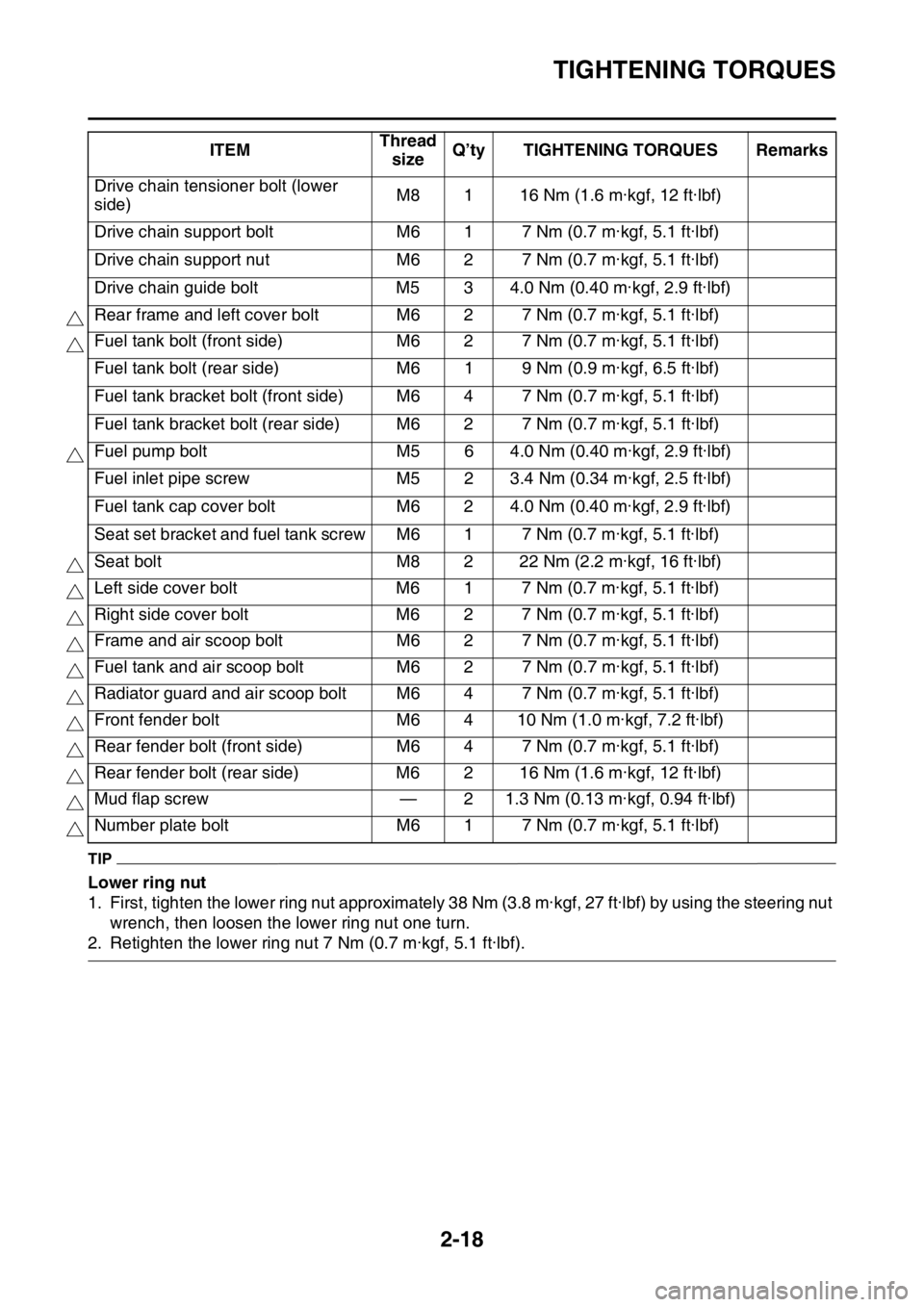
2. Retighten the lower ring nut 7 Nm (0.7 m·kgf, 5.1 ft·lbf).Drive chain tensioner bolt (lower
side)M8 1 16 Nm (1.6 m·kgf, 12 ft·lbf)
Drive chain support bolt M6 1 7 Nm (0.7 m·kgf, 5.1 ft·lbf)
Drive chain support nut M6 2 7 Nm (0.7 m·kgf, 5.1 ft·lbf)
Drive chain guide bolt M5 3 4.0 Nm (0.40 m·kgf, 2.9 ft·lbf)
Rear frame and left cover bolt M6 2 7 Nm (0.7 m·kgf, 5.1 ft·lbf)
Fuel tank bolt (front side) M6 2 7 Nm (0.7 m·kgf, 5.1 ft·lbf)
Fuel tank bolt (rear side) M6 1 9 Nm (0.9 m·kgf, 6.5 ft·lbf)
Fuel tank bracket bolt (front side) M6 4 7 Nm (0.7 m·kgf, 5.1 ft·lbf)
Fuel tank bracket bolt (rear side) M6 2 7 Nm (0.7 m·kgf, 5.1 ft·lbf)
Fuel pump bolt M5 6 4.0 Nm (0.40 m·kgf, 2.9 ft·lbf)
Fuel inlet pipe screw M5 2 3.4 Nm (0.34 m·kgf, 2.5 ft·lbf)
Fuel tank cap cover bolt M6 2 4.0 Nm (0.40 m·kgf, 2.9 ft·lbf)
Seat set bracket and fuel tank screw M6 1 7 Nm (0.7 m·kgf, 5.1 ft·lbf)
Seat bolt M8 2 22 Nm (2.2 m·kgf, 16 ft·lbf)
Left side cover bolt M6 1 7 Nm (0.7 m·kgf, 5.1 ft·lbf)
Right side cover bolt M6 2 7 Nm (0.7 m·kgf, 5.1 ft·lbf)
Frame and air scoop bolt M6 2 7 Nm (0.7 m·kgf, 5.1 ft·lbf)
Fuel tank and air scoop bolt M6 2 7 Nm (0.7 m·kgf, 5.1 ft·lbf)
Radiator guard and air scoop bolt M6 4 7 Nm (0.7 m·kgf, 5.1 ft·lbf)
Front fender bolt M6 4 10 Nm (1.0 m·kgf, 7.2 ft·lbf)
Rear fender bolt (front side) M6 4 7 Nm (0.7 m·kgf, 5.1 ft·lbf)
Rear fender bolt (rear side) M6 2 16 Nm (1.6 m·kgf, 12 ft·lbf)
Mud flap screw — 2 1.3 Nm (0.13 m·kgf, 0.94 ft·lbf)
Number plate bolt M6 1 7 Nm (0.7 m·kgf, 5.1 ft·lbf)ITEMThread
sizeQ’ty TIGHTENING TORQUES Remarks
Page 77 of 356

CABLE ROUTING DIAGRAM
2-34
1. Bracket
2. Condenser
3. Coolant temperature sensor
4. Coupler cover
5. Intake air temperature sensor coupler
6. Intake air temperature sensor coupler
7. Radiator hoses
8. Radiator breather hose
9. Joint coupler
10. Plate
11. Tension arm
12. Throttle position sensor lead
13. Ground lead
14. Throttle position sensor coupler
15. Radiator breather hose
16. Cylinder head breather hose
17. Engine guard
18. Crankcase
19. Fuel pump coupler
20. Fuel hose
21. Condenser lead
22. Fuel pump lead
23. Condenser coupler
24. Ground lead terminal
25. Fuel tank
26. Damper
27. Rear frame
28. Main harness
A. Insert the condenser into the bracket as far as it
will go.
B. Attach the coupler cover to the coolant tempera-
ture sensor coupler.
C. Pass the radiator breather hose to the inside of
the radiator hose (the side of the vehicle).
D. Insert and fix the joint coupler to the plate. After
fixing it, attach the cover.
E. Pass the throttle position sensor lead to the out-
side of the tension arm (the outside of the vehi-
cle).
F. After connecting the throttle position sensor cou-
pler, attach the cover.
G. Pass the radiator breather hose to the outside of
the tension arm and the throttle position sensor
lead (the outside of the vehicle), and to the inside
of the radiator hose (the side of the vehicle).
H. Pass the protector of the cylinder head breather
hose until it touches the holder.
I. Pass the cylinder head breather hose between
the engine guard and the crankcase.
J. Install the end of the cylinder head breather hose
with it facing downward.
K. After connecting the fuel pump coupler, attach
the coupler cover.
L. 55 mm (2.17 in) (seat load receiver)
M. Clamp the fuel hose and the fuel pump lead by
the holder. Make sure that the painted part on the
fuel hose is clamped, and face the lock on the
clamp toward the rear top of the vehicle.
N. Do not install the plastic locking tie to the seat
load receiver.
O. Make the lock on the plastic locking tie face the
front of the vehicle, and make the end face the
bottom of the vehicle. Do not cut the end.
P. Install the ground lead terminal between the plate
and the bolt.
Q. Detent
R. Fix the ground lead terminal to the detent in the
plate. For the ground lead terminal, either side
will do.S. Insert the projection on the plastic locking tie into
the hole in the rear frame.
T. Clamp the painted part on the fuel hose by the
plastic clamp. Make the lock on the plastic clamp
face the bottom of the vehicle, and cut the end.
Page 90 of 356
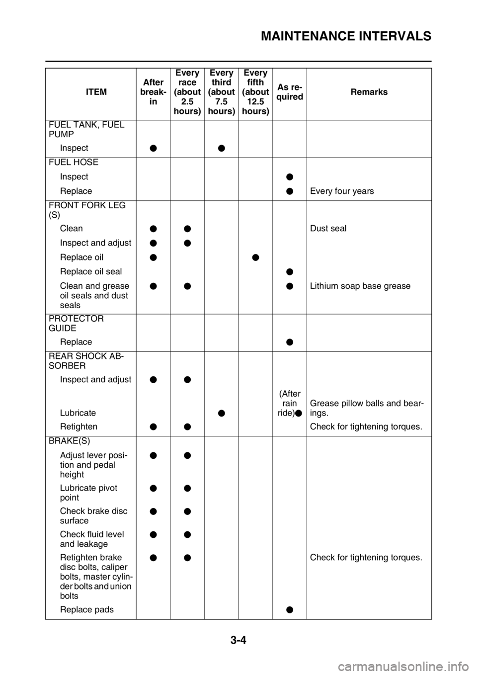
MAINTENANCE INTERVALS
3-4
FUEL TANK, FUEL
PUMP
Inspect
FUEL HOSE
Inspect
Replace Every four years
FRONT FORK LEG
(S)
Clean Dust seal
Inspect and adjust
Replace oil
Replace oil seal
Clean and grease
oil seals and dust
sealsLithium soap base grease
PROTECTOR
GUIDE
Replace
REAR SHOCK AB-
SORBER
Inspect and adjust
Lubricate(After
rain
ride)Grease pillow balls and bear-
ings.
Retighten Check for tightening torques.
BRAKE(S)
Adjust lever posi-
tion and pedal
height
Lubricate pivot
point
Check brake disc
surface
Check fluid level
and leakage
Retighten brake
disc bolts, caliper
bolts, master cylin-
der bolts and union
boltsCheck for tightening torques.
Replace padsITEMAfter
break-
inEvery
race
(about
2.5
hours)Every
third
(about
7.5
hours)Every
fifth
(about
12.5
hours)As re-
quiredRemarks
Page 102 of 356
ENGINE
3-16
7. Pour the specified amount of engine oil into
the oil filler cap hole.
8. Install:
• Oil filler cap
9. Check:
• Oil level
Refer to “CHECKING THE ENGINE OIL
LEVEL” on page 3-14.
10.Check:
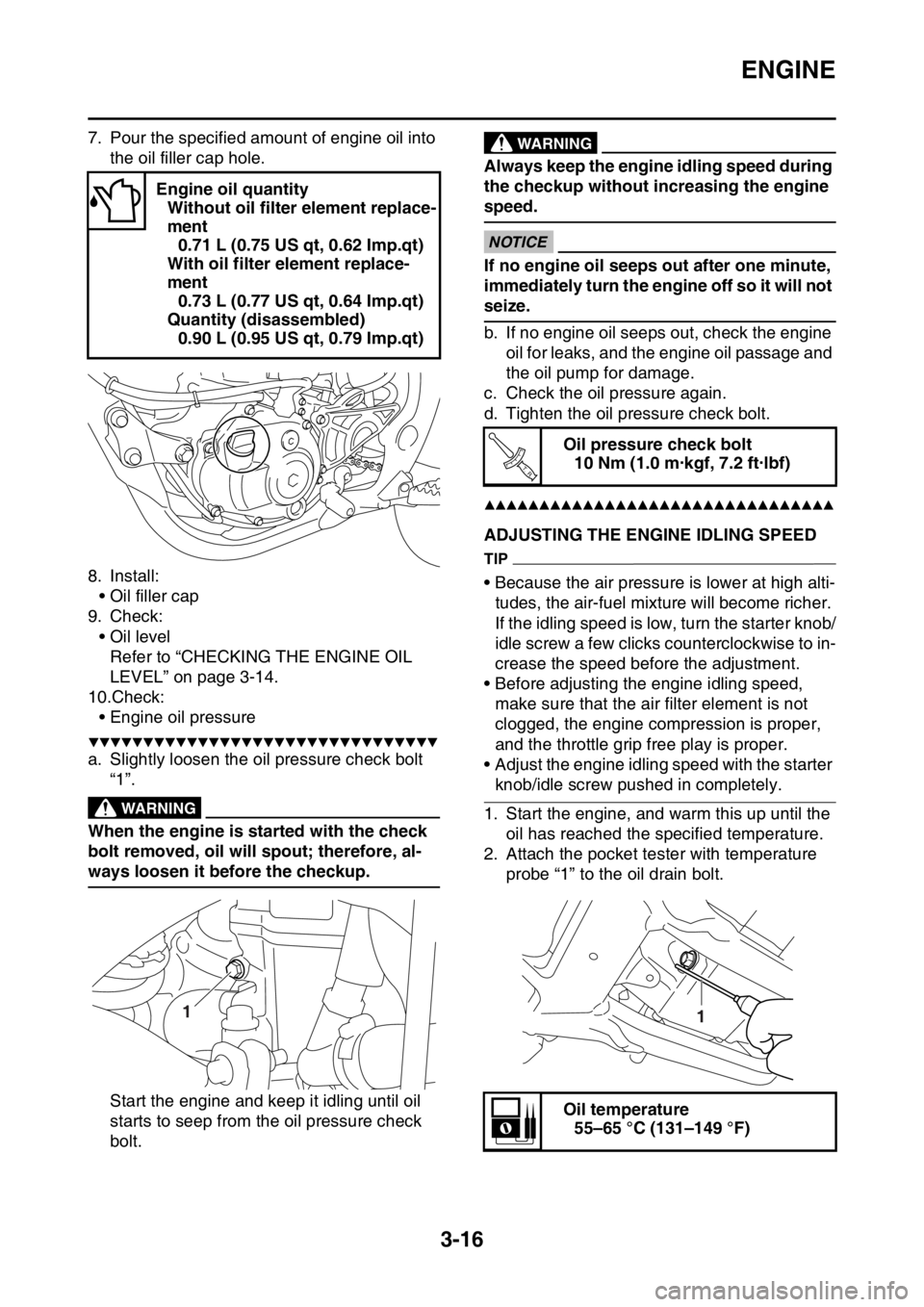
• Engine oil pressure
▼▼▼▼▼▼▼▼▼▼▼▼▼▼▼▼▼▼▼▼▼▼▼▼▼▼▼▼▼▼▼▼
a. Slightly loosen the oil pressure check bolt
“1”.
EWA
WARNING
When the engine is started with the check
bolt removed, oil will spout; therefore, al-
ways loosen it before the checkup.
Start the engine and keep it idling until oil
starts to seep from the oil pressure check
bolt.
EWA
WARNING
Always keep the engine idling speed during
the checkup without increasing the engine
speed.
ECA
NOTICE
If no engine oil seeps out after one minute,
immediately turn the engine off so it will not
seize.
b. If no engine oil seeps out, check the engine
oil for leaks, and the engine oil passage and
the oil pump for damage.
c. Check the oil pressure again.
d. Tighten the oil pressure check bolt.
▲▲▲▲▲▲▲▲▲▲▲▲▲▲▲▲▲▲▲▲▲▲▲▲▲▲▲▲▲▲▲▲
EAS1SM5088ADJUSTING THE ENGINE IDLING SPEED
TIP
• Because the air pressure is lower at high alti-
tudes, the air-fuel mixture will become richer.
If the idling speed is low, turn the starter knob/
idle screw a few clicks counterclockwise to in-
crease the speed before the adjustment.
• Before adjusting the engine idling speed,
make sure that the air filter element is not
clogged, the engine compression is proper,
and the throttle grip free play is proper.
• Adjust the engine idling speed with the starter
knob/idle screw pushed in completely.
1. Start the engine, and warm this up until the
oil has reached the specified temperature.
2. Attach the pocket tester with temperature
probe “1” to the oil drain bolt. Engine oil quantity
Without oil filter element replace-
ment
0.71 L (0.75 US qt, 0.62 Imp.qt)
With oil filter element replace-
ment
0.73 L (0.77 US qt, 0.64 Imp.qt)
Quantity (disassembled)
0.90 L (0.95 US qt, 0.79 Imp.qt)
1
Oil pressure check bolt
10 Nm (1.0 m·kgf, 7.2 ft·lbf)
Oil temperature
55–65 °C (131–149 °F)
T R..
1