YAMAHA YZ250F 2016 User Guide
Manufacturer: YAMAHA, Model Year: 2016, Model line: YZ250F, Model: YAMAHA YZ250F 2016Pages: 356, PDF Size: 11.25 MB
Page 11 of 356

1
2
3
4
5
6
7
8
9
10 TABLE OF CONTENTS
GENERAL INFORMATION
SPECIFICATIONS
PERIODIC CHECKS AND
ADJUSTMENTS
CHASSIS
ENGINE
COOLING SYSTEM
FUEL SYSTEM
ELECTRICAL SYSTEM
TROUBLESHOOTING
TUNING
Page 12 of 356

Page 13 of 356

1
GENERAL INFORMATION
LOCATION OF IMPORTANT LABELS............................................................ 1-1
DESCRIPTION.................................................................................................. 1-4
IDENTIFICATION............................................................................................. 1-5
VEHICLE IDENTIFICATION NUMBER ...................................................... 1-5
ENGINE SERIAL NUMBER ....................................................................... 1-5
INCLUDED PARTS.......................................................................................... 1-6
SIDESTAND ............................................................................................... 1-6
SPARK PLUG WRENCH ........................................................................... 1-6
NIPPLE WRENCH...................................................................................... 1-6
HANDLEBAR PROTECTOR ...................................................................... 1-6
FUEL HOSE JOINT COVER ...................................................................... 1-6
COUPLER FOR CONNECTING OPTIONAL PART................................... 1-6
IMPORTANT INFORMATION.......................................................................... 1-8
PREPARATION FOR REMOVAL AND DISASSEMBLY............................ 1-8
REPLACEMENT PARTS............................................................................ 1-8
GASKETS, OIL SEALS AND O-RINGS ..................................................... 1-9
LOCK WASHERS/PLATES AND COTTER PINS ...................................... 1-9
BEARINGS AND OIL SEALS ..................................................................... 1-9
CIRCLIPS ................................................................................................... 1-9
BASIC SERVICE INFORMATION.................................................................. 1-10
ELECTRICAL SYSTEM............................................................................ 1-10
SPECIAL TOOLS........................................................................................... 1-13
CONTROL FUNCTIONS................................................................................ 1-18
ENGINE STOP SWITCH .......................................................................... 1-18
CLUTCH LEVER...................................................................................... 1-18
SHIFT PEDAL .......................................................................................... 1-18
KICKSTARTER LEVER............................................................................ 1-18
THROTTLE GRIP ..................................................................................... 1-18
FRONT BRAKE LEVER ........................................................................... 1-18
REAR BRAKE PEDAL.............................................................................. 1-19
STARTER KNOB/IDLE ADJUSTING SCREW ......................................... 1-19
FUEL TANK CAP ..................................................................................... 1-19
Page 14 of 356

STARTING AND BREAK-IN.......................................................................... 1-20
FUEL ........................................................................................................ 1-20
STARTING A COLD ENGINE .................................................................. 1-20
STARTING A WARM ENGINE ................................................................. 1-21
BREAK-IN PROCEDURES ...................................................................... 1-21
MAINTENANCE AFTER BREAK-IN.............................................................. 1-22
MAJOR MAINTENANCE .......................................................................... 1-22
TORQUE-CHECK POINTS............................................................................ 1-23
CLEANING AND STORAGE.......................................................................... 1-25
CLEANING ............................................................................................... 1-25
STORAGE ................................................................................................ 1-25
Page 15 of 356
LOCATION OF IMPORTANT LABELS
1-1
EAS1SM9008
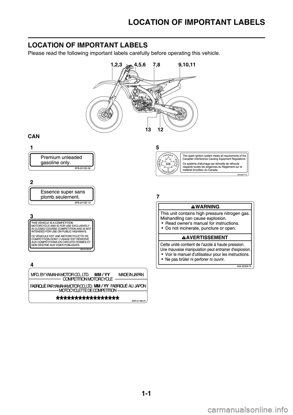
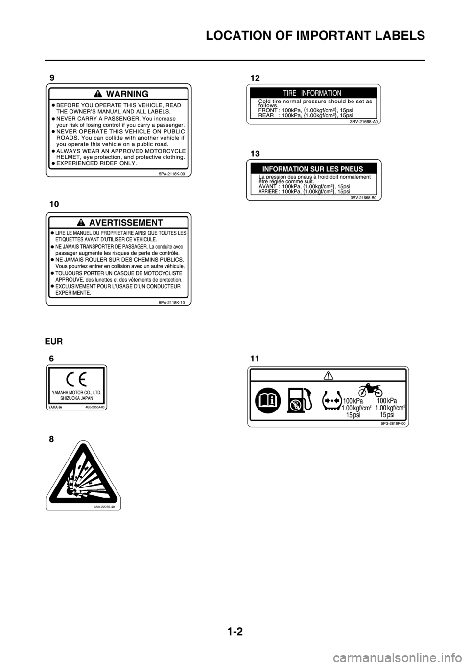
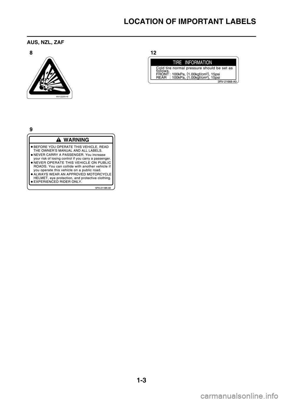
LOCATION OF IMPORTANT LABELS
Please read the following important labels carefully before operating this vehicle.
CAN
9,10,11 7,8
13
12 1,2,3 4,5,6
Page 16 of 356
LOCATION OF IMPORTANT LABELS
1-2
EUR
Page 17 of 356
LOCATION OF IMPORTANT LABELS
1-3
AUS, NZL, ZAF
Page 18 of 356
DESCRIPTION
1-4
EAS1SM9009
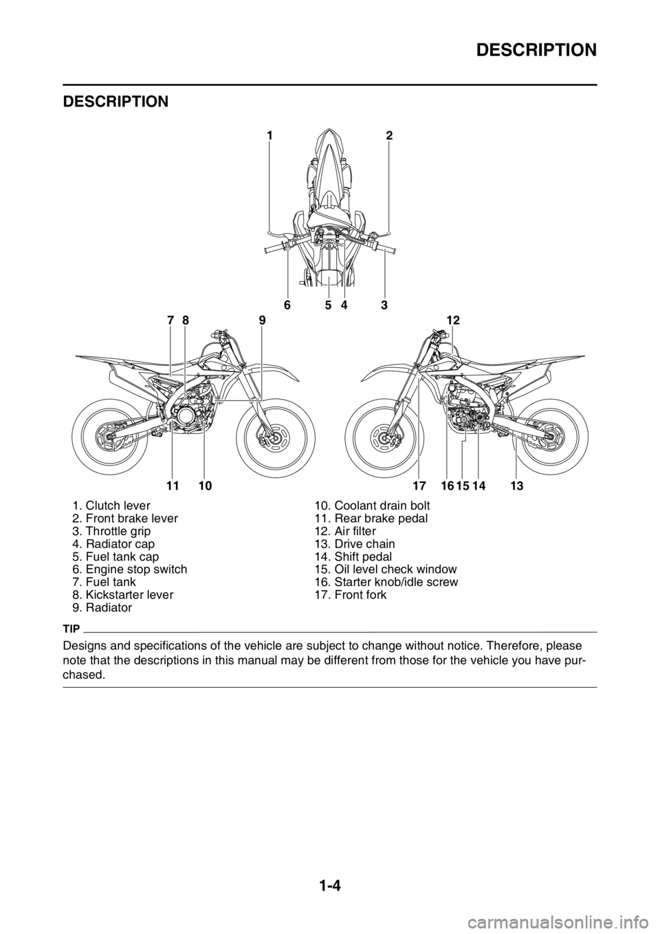
DESCRIPTION
TIP
Designs and specifications of the vehicle are subject to change without notice. Therefore, please
note that the descriptions in this manual may be different from those for the vehicle you have pur-
chased.1. Clutch lever 10. Coolant drain bolt
2. Front brake lever 11. Rear brake pedal
3. Throttle grip 12. Air filter
4. Radiator cap 13. Drive chain
5. Fuel tank cap 14. Shift pedal
6. Engine stop switch 15. Oil level check window
7. Fuel tank 16. Starter knob/idle screw
8. Kickstarter lever 17. Front fork
9. Radiator
2 1
6
78 954 3
11 10 17 16 15 14 1312
Page 19 of 356
IDENTIFICATION
1-5
EAS1SM9010
IDENTIFICATION
There are two significant reasons for knowing
the serial number of your vehicle:
1. When ordering parts, you can give the num-
ber to your Yamaha dealer for positive iden-
tification of the model you own.
2. If your vehicle is stolen, the authorities will
need the number to search for and identify
your vehicle.
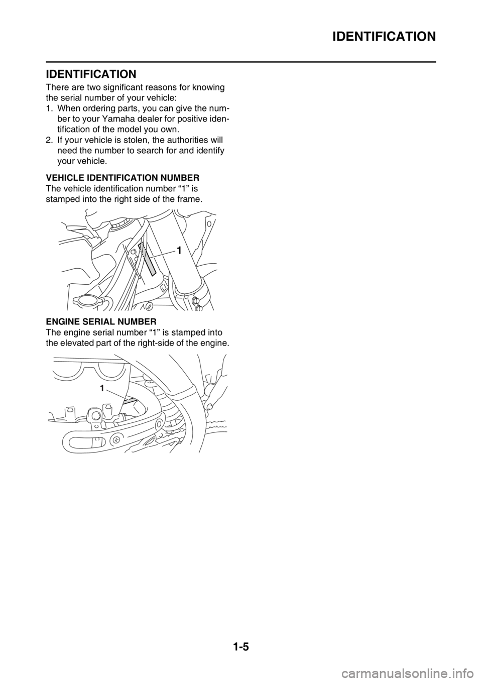
EAS1SM9011VEHICLE IDENTIFICATION NUMBER
The vehicle identification number “1” is
stamped into the right side of the frame.
EAS1SM9012ENGINE SERIAL NUMBER
The engine serial number “1” is stamped into
the elevated part of the right-side of the engine.
1
1
Page 20 of 356
INCLUDED PARTS
1-6
EAS1SM9013
INCLUDED PARTS
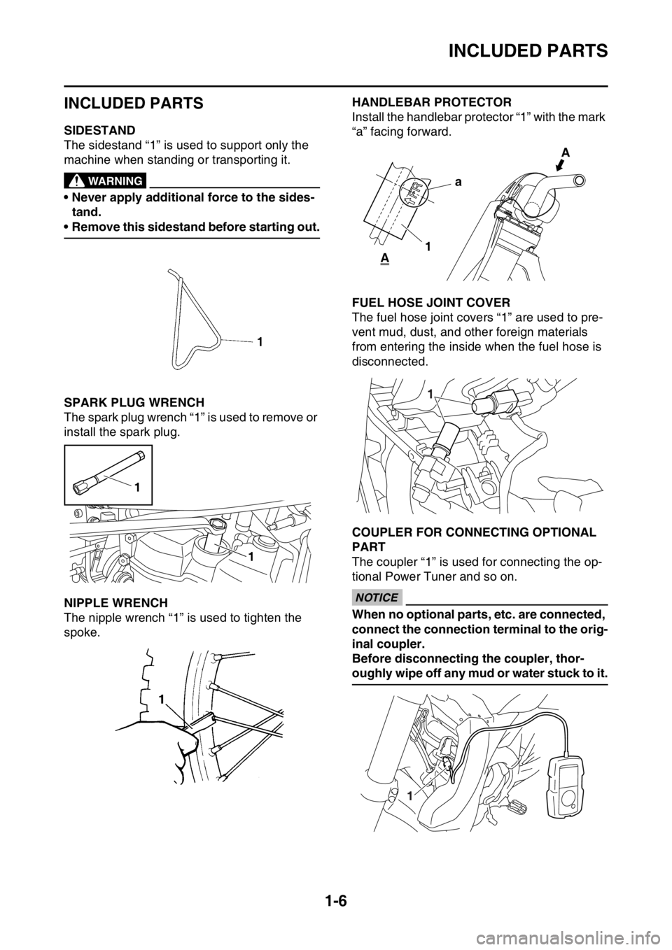
EAS1SM9014SIDESTAND
The sidestand “1” is used to support only the
machine when standing or transporting it.
EWA@
WARNING
• Never apply additional force to the sides-
tand.
• Remove this sidestand before starting out.
EAS1SM9015SPARK PLUG WRENCH
The spark plug wrench “1” is used to remove or
install the spark plug.
EAS1SM9016NIPPLE WRENCH
The nipple wrench “1” is used to tighten the
spoke.
EAS1SM9017HANDLEBAR PROTECTOR
Install the handlebar protector “1” with the mark
“a” facing forward.
EAS1SM9018FUEL HOSE JOINT COVER
The fuel hose joint covers “1” are used to pre-
vent mud, dust, and other foreign materials
from entering the inside when the fuel hose is
disconnected.
EAS1SM9019COUPLER FOR CONNECTING OPTIONAL
PART
The coupler “1” is used for connecting the op-
tional Power Tuner and so on.
ECA
NOTICE
When no optional parts, etc. are connected,
connect the connection terminal to the orig-
inal coupler.
Before disconnecting the coupler, thor-
oughly wipe off any mud or water stuck to it.
1
1
a
1A
A
1
1