water pump remove YAMAHA YZ250F 2016 Owners Manual
[x] Cancel search | Manufacturer: YAMAHA, Model Year: 2016, Model line: YZ250F, Model: YAMAHA YZ250F 2016Pages: 356, PDF Size: 11.25 MB
Page 22 of 356
IMPORTANT INFORMATION
1-8
EAS20180
IMPORTANT INFORMATION
EAS1SM9020PREPARATION FOR REMOVAL AND DIS-
ASSEMBLY
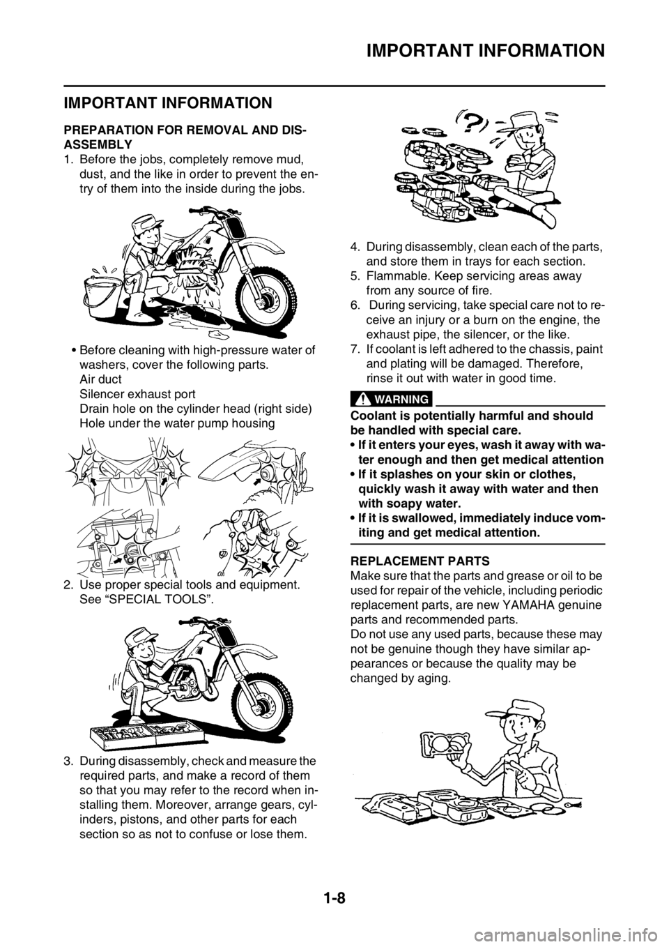
1. Before the jobs, completely remove mud,
dust, and the like in order to prevent the en-
try of them into the inside during the jobs.
• Before cleaning with high-pressure water of
washers, cover the following parts.
Air duct
Silencer exhaust port
Drain hole on the cylinder head (right side)
Hole under the water pump housing
2. Use proper special tools and equipment.
See “SPECIAL TOOLS”.
3. During disassembly, check and measure the
required parts, and make a record of them
so that you may refer to the record when in-
stalling them. Moreover, arrange gears, cyl-
inders, pistons, and other parts for each
section so as not to confuse or lose them.4. During disassembly, clean each of the parts,
and store them in trays for each section.
5. Flammable. Keep servicing areas away
from any source of fire.
6. During servicing, take special care not to re-
ceive an injury or a burn on the engine, the
exhaust pipe, the silencer, or the like.
7. If coolant is left adhered to the chassis, paint
and plating will be damaged. Therefore,
rinse it out with water in good time.
EWA
WARNING
Coolant is potentially harmful and should
be handled with special care.
• If it enters your eyes, wash it away with wa-
ter enough and then get medical attention
• If it splashes on your skin or clothes,
quickly wash it away with water and then
with soapy water.
• If it is swallowed, immediately induce vom-
iting and get medical attention.
EAS1SM9021REPLACEMENT PARTS
Make sure that the parts and grease or oil to be
used for repair of the vehicle, including periodic
replacement parts, are new YAMAHA genuine
parts and recommended parts.
Do not use any used parts, because these may
not be genuine though they have similar ap-
pearances or because the quality may be
changed by aging.
Page 139 of 356
FRONT BRAKE
4-15
EAS1SM9134INTRODUCTIONEWA
WARNING
If you need to disassemble the disc brake
components, observe the following precau-
tions.
• Never disassemble the brake components
unless absolutely necessary.
• If there is any problem with connections
on the hydraulic brake system, perform
the following jobs.
Disassemble the brake system, drain the
brake fluid, and clean it. After that, add a
suitable amount of brake fluid. Then, bleed
it after reassembly.
• Use only brake fluid for washing brake
components.
• Use new brake fluid for cleaning the brake
components.
• Immediately wipe off the spilled brake fluid
to avoid damage to painted surfaces or
plastic parts.
• Handle brake fluid with special care not to
let it enter your eyes so that you may not
lost your eyesight.
• FIRST AID FOR BRAKE FLUID ENTERING
THE EYES:
• Flush with water for 15 minutes and get
immediate medical attention.
EAS1SM9135CHECKING THE FRONT BRAKE DISC
1. Remove:
• Front wheel
Refer to “FRONT WHEEL” on page 4-3.
2. Check:
• Front brake disc
Damage/galling Replace.
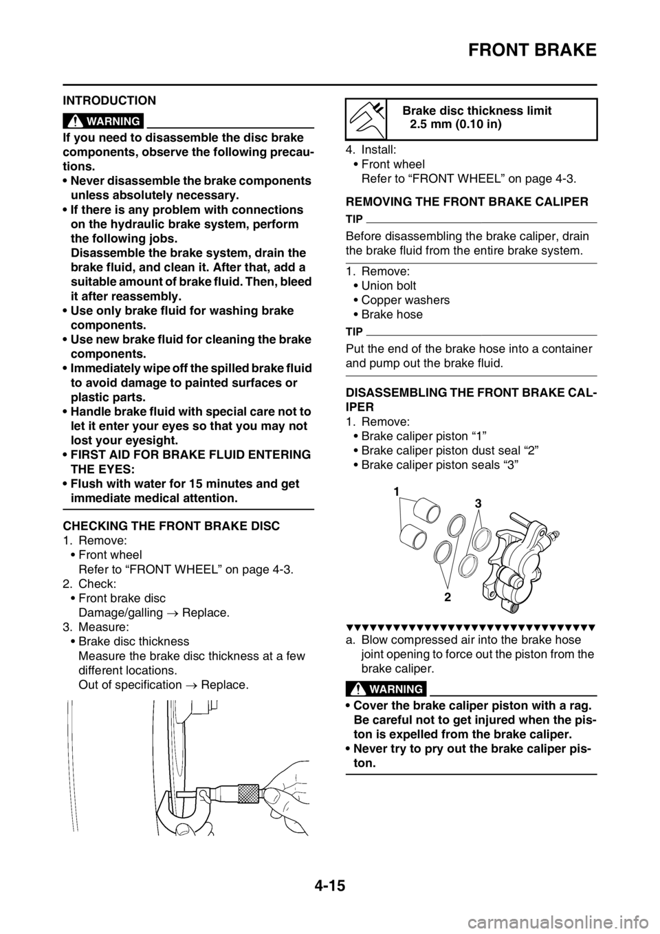
3. Measure:
• Brake disc thickness
Measure the brake disc thickness at a few
different locations.
Out of specification Replace.4. Install:
• Front wheel
Refer to “FRONT WHEEL” on page 4-3.
EAS1SM9136REMOVING THE FRONT BRAKE CALIPER
TIP
Before disassembling the brake caliper, drain
the brake fluid from the entire brake system.
1. Remove:
• Union bolt
• Copper washers
• Brake hose
TIP
Put the end of the brake hose into a container
and pump out the brake fluid.
EAS1SM9137DISASSEMBLING THE FRONT BRAKE CAL-
IPER
1. Remove:
• Brake caliper piston “1”
• Brake caliper piston dust seal “2”
• Brake caliper piston seals “3”
▼▼▼▼▼▼▼▼▼▼▼▼▼▼▼▼▼▼▼▼▼▼▼▼▼▼▼▼▼▼▼▼
a. Blow compressed air into the brake hose
joint opening to force out the piston from the
brake caliper.
EWA
WARNING
• Cover the brake caliper piston with a rag.
Be careful not to get injured when the pis-
ton is expelled from the brake caliper.
• Never try to pry out the brake caliper pis-
ton.
Brake disc thickness limit
2.5 mm (0.10 in)
3
2
1
Page 273 of 356
WATER PUMP
6-6
EAS1SM9298REMOVING THE OIL SEAL
TIP
• Remove the oil seal when the coolant level
changes frequently more than usual, coolant
has discolored, or engine oil has become
milky.
• Do not use the removed oil seal.
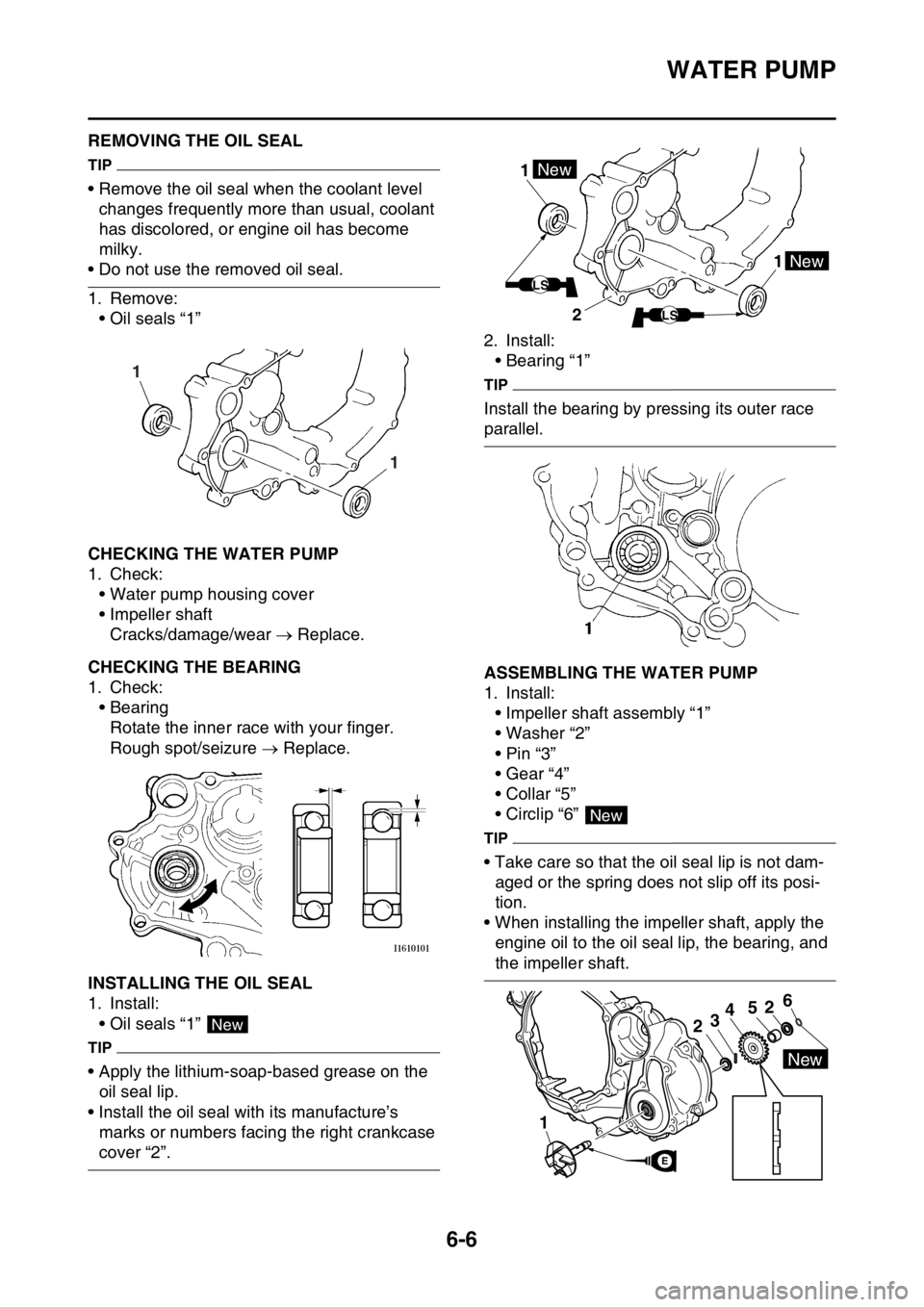
1. Remove:
• Oil seals “1”
EAS1SM9299CHECKING THE WATER PUMP
1. Check:
• Water pump housing cover
• Impeller shaft
Cracks/damage/wear Replace.
EAS1SM9300CHECKING THE BEARING
1. Check:
• Bearing
Rotate the inner race with your finger.
Rough spot/seizure Replace.
EAS1SM9301INSTALLING THE OIL SEAL
1. Install:
• Oil seals “1”
TIP
• Apply the lithium-soap-based grease on the
oil seal lip.
• Install the oil seal with its manufacture’s
marks or numbers facing the right crankcase
cover “2”.2. Install:
• Bearing “1”
TIP
Install the bearing by pressing its outer race
parallel.
EAS1SM9302ASSEMBLING THE WATER PUMP
1. Install:
• Impeller shaft assembly “1”
• Washer “2”
•Pin “3”
• Gear “4”
• Collar “5”
• Circlip “6”
TIP
• Take care so that the oil seal lip is not dam-
aged or the spring does not slip off its posi-
tion.
• When installing the impeller shaft, apply the
engine oil to the oil seal lip, the bearing, and
the impeller shaft.
1 1
New
1 1New
New
LS
LS2
New
1
2
52346
New
E