sensor YAMAHA YZ250LC 2001 Manuale duso (in Italian)
[x] Cancel search | Manufacturer: YAMAHA, Model Year: 2001, Model line: YZ250LC, Model: YAMAHA YZ250LC 2001Pages: 578, PDF Dimensioni: 14.12 MB
Page 242 of 578

ENG
4-16
CARBURETOR AND REED VALVE
11. Install:
9Mixing chamber top 1
9Screw(mixing chamber top) 2
To carburetor 3.
NOTE:
9Insert the throttle valve into the carburetor body
while pulling up the lever 4.
9Pass the throttle cable 5at the front (on the
cylinder side) of the air vent hose.
9After installing, check the throttle grip for
smooth movement.
EC465390
Carburetor installation
1. Install:
9Carburetor 1
NOTE:
Install the projection between the carburetor joint
slots.
2. Tighten:
9Screw (air cleaner joint) 1
9Screw (carburetor joint) 2
3. Connect:
9TPS (throttle position sensor) lead 1
9Solenoid valve lead 2
Refer to “CABLE ROUTING DIAGRAM”
section in the CHAPTER 2.
4. Adjust:
9Idle speed
Refer to “IDLE SPEED ADJUSTMENT”
section in the CHAPTER 3.
5MW-9-30-4A 7/3/00 5:27 PM Page 32
Page 243 of 578

ENG
4-16
CARBURATEUR ET SOUPAPE FLEXIBLE
VERGASER UND ZUNGENVENTIL
CARBURATORE E VALVOLA A LAMELLA
Montage du carburateur
1. Monter:
9Carburateur 1
N.B.:
Mettre la projection en place entre les
fentes de raccord du carburateur.
IC465390Installazione del carburatore
1. Installare:
9Carburatore 1
NOTA:
Installare la sporgenza tra le fessure del
giunto del carburatore.
Einbau des Vergasers
1 Einbauen:
9Vergaser 1
ANMERKUNG:
Die Nase zwischen den Vergaserver-
bindungsschlitzen anordnen.
2. Serrer:
9Vis (raccord du filtre à air) 1
9Vis (raccord du carburateur ) 22. Serrare:
9Vite (giunto del filtro dell’aria)
1
9Vite (giunto del carburatore) 22. Festziehen:
9Schraube (Luftfilterverbindung)
1
9Schraube (Vergaserverbin-
dung) 2
3. Connecter:
9Fil du TPS (capteur de position
du papillon) 1
9Fil d’électrovanne 2
Se reporter à la section “CHE-
MINEMENT DES CABLES”
du CHAPITRE 2.
4. Régler:
9Régime de ralenti
Se reporter à la section
“REGLAGE DU REGIME DE
RALENTI” du CHAPITRE 3.3. Collegare:
9Conduttore TPS (sensore di
posizione gas) 1
9Conduttore elettrovalvola 2
Consultare la sezione “DIA-
GRAMMA DEL PASSAGGIO
DEI CAVI” al CAPITOLO 2.
4. Regolare:
9Numero di giri al minimo
Consultare la sezione “REGO-
LAZIONE DEL NUMERO DI
GIRI AL MINIMO” al CAPI-
TOLO 3.3. Anschließen:
9TPS-Leitungskabel (Drossel-
stellungssensor) 1
9Magnetventilleitung 2
Siehe Abschnitt „KABEL-
FÜHRUNGSÜBERSICHT-
PLAN“ im KAPITEL 2.
4. Einstellen:
9Leerlaufdrehzahl
Siehe Abschnitt „EINSTEL-
LUNG DER LEERLAUFDREH-
ZAHL“ im KAPITEL 3.
11. Monter:
9Haut de chambre de mélange 1
9Vis (haut de chambre de mélan-
ge) 2
Au carburateur 3.
N.B.:
9Insérer le boisseau dans le corps du
carburateur tout en maintenant le
levier 4relevé.
9Faire passer le câble d’accélérateur 5
à l’avant du tuyau de ventilation du
côté du cylindre.
9Après avoir réalisé le montage, véri-
fier que l’attache des gaz se déplace
sans à-coup.
11. Einbauen:
9Mischkammer-Oberteil 1
9Schraube (Mischkammer-
Oberteil) 2
An dem Vergaser 3.
ANMERKUNG:
9Drosselventil bei hochgezogenem
Hebel 4in das Vergasergehäuse
einbringen und auf Bewegungsfrei-
heit prüfen.
9Das Gasseil 5vorder dem Belüf-
tungsschlauch an der Zylinderseite
durchführen.
9Nach dem Einbau ist der Gasdreh-
griff auf glatte Bewegung zu prüfen.
11. Installare:
9Parte superiore del diffusore 1
9Vite (parte superiore del diffu-
sore) 2
Sul carburatore 3.
NOTA:
9Inserire la valvola a farfalla nel corpo
del carburatore tirando contempora-
neamente la leva 4verso l’alto.
9Far passare il cavo dell’acceleratore
5davanti (sul lato del cilindro) al
tubo di sfiato dell’aria.
9Dopo l’installazione, controllare che
la manopola dell’acceleratore si
muova senza difficoltà.
5MW-9-30-4A 7/3/00 5:27 PM Page 33
Page 490 of 578
6-1
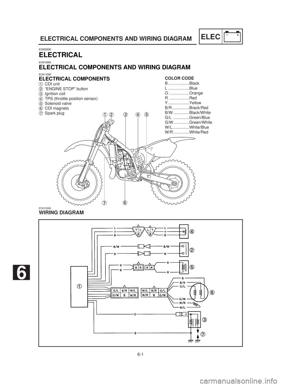
ELECTRICAL COMPONENTS AND WIRING DIAGRAMELEC
EC600000
ELECTRICAL
EC610000
ELECTRICAL COMPONENTS AND WIRING DIAGRAM
EC611000
ELECTRICAL COMPONENTS
1CDI unit
2“ENGINE STOP” button
3Ignition coil
4TPS (throttle position sensor)
5Solenoid valve
6CDI magneto
7Spark plug
EC612000
WIRING DIAGRAM
COLOR CODE
B...................Black
L ...................Blue
O ..................Orange
R ..................Red
Y...................Yellow
B/R ...............Brack/Red
B/W ..............Black/White
G/L ..............Green/Blue
G/W ..............Green/White
W/L...............White/Blue
W/R ..............White/Red
6
5MW-9-30-6 7/6/00 1:34 PM Page 2
Page 491 of 578
6-1
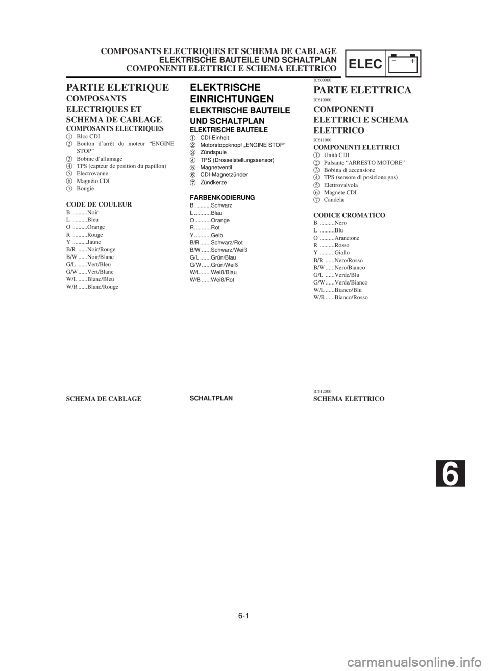
COMPOSANTS ELECTRIQUES ET SCHEMA DE CABLAGE
ELEKTRISCHE BAUTEILE UND SCHALTPLAN
COMPONENTI ELETTRICI E SCHEMA ELETTRICOELEC
ELEKTRISCHE
EINRICHTUNGEN
ELEKTRISCHE BAUTEILE
UND SCHALTPLAN
ELEKTRISCHE BAUTEILE1CDI-Einheit
2Motorstoppknopf „ENGINE STOP“
3Zündspule
4TPS (Drosselstellungssensor)
5Magnetventil
6CDI-Magnetzünder
7Zündkerze
FARBENKODIERUNGB...........Schwarz
L ...........Blau
O ..........Orange
R...........Rot
Y ...........Gelb
B/R .......Schwarz/Rot
B/W ......Schwarz/Weiß
G/L .......Grün/Blau
G/W ......Grün/Weiß
W/L .......Weiß/Blau
W/B ......Weiß/Rot
SCHALTPLAN
PARTIE ELETRIQUE
COMPOSANTS
ELECTRIQUES ET
SCHEMA DE CABLAGE
COMPOSANTS ELECTRIQUES1Bloc CDI
2Bouton d’arrêt du moteur “ENGINE
STOP”
3Bobine d’allumage
4TPS (capteur de position du papillon)
5Electrovanne
6Magnéto CDI
7Bougie
CODE DE COULEURB ..........Noir
L ..........Bleu
O ..........Orange
R ..........Rouge
Y ..........Jaune
B/R ......Noir/Rouge
B/W ......Noir/Blanc
G/L ......Vert/Bleu
G/W ......Vert/Blanc
W/L ......Blanc/Bleu
W/R ......Blanc/Rouge
SCHEMA DE CABLAGE
IC600000
PARTE ELETTRICA
IC610000
COMPONENTI
ELETTRICI E SCHEMA
ELETTRICO
IC611000
COMPONENTI ELETTRICI1Unità CDI
2Pulsante “ARRESTO MOTORE”
3Bobina di accensione
4TPS (sensore di posizione gas)
5Elettrovalvola
6Magnete CDI
7Candela
CODICE CROMATICOB ..........Nero
L ..........Blu
O ..........Arancione
R ..........Rosso
Y ..........Giallo
B/R ......Nero/Rosso
B/W ......Nero/Bianco
G/L ......Verde/Blu
G/W ......Verde/Bianco
W/L ......Bianco/Blu
W/R ......Bianco/Rosso
IC612000
SCHEMA ELETTRICO
6
5MW-9-30-6 7/6/00 1:34 PM Page 3
Page 508 of 578

6-8
TPS (THROTTLE POSITION SENSOR) SYSTEMELEC
Check entire ignition
system for connection.Repair or replace.
OK
OKTPS coil
No goodReplace.Check TPS.
OKSource coil
No goodReplace.*Check CDI magneto.
TPS input
voltageNo goodReplace.Check CDI unit.
No good
EC690000
TPS (THROTTLE POSITION SENSOR) SYSTEM
EC691001
INSPECTION STEPS
If the TPS will not operate, use the following inspection steps.
*marked: Refer to “IGNITION SYSTEM” section.
NOTE:
9Remove the following parts before inspection.
1) Seat
2) Fuel tank
9Use the following special tools in this inspection.
Inductive tachometer:
YU-8036-B
Engine tachometer:
90890-03113Pocket tester:
YU-3112-C/90890-03112
5MW-9-30-6 7/6/00 1:37 PM Page 20
Page 510 of 578
6-8
TPS-SYSTEM (TPS = DROSSELSTELLUNGSSENSOR)ELEC
TPS-Spule
Erneuern oder reparieren.Die Anschlüsse der gesamten
Zündanlage kontrollieren.Nicht in Ordnung
Nicht in OrdnungTPS kontrollieren.Erneuern.
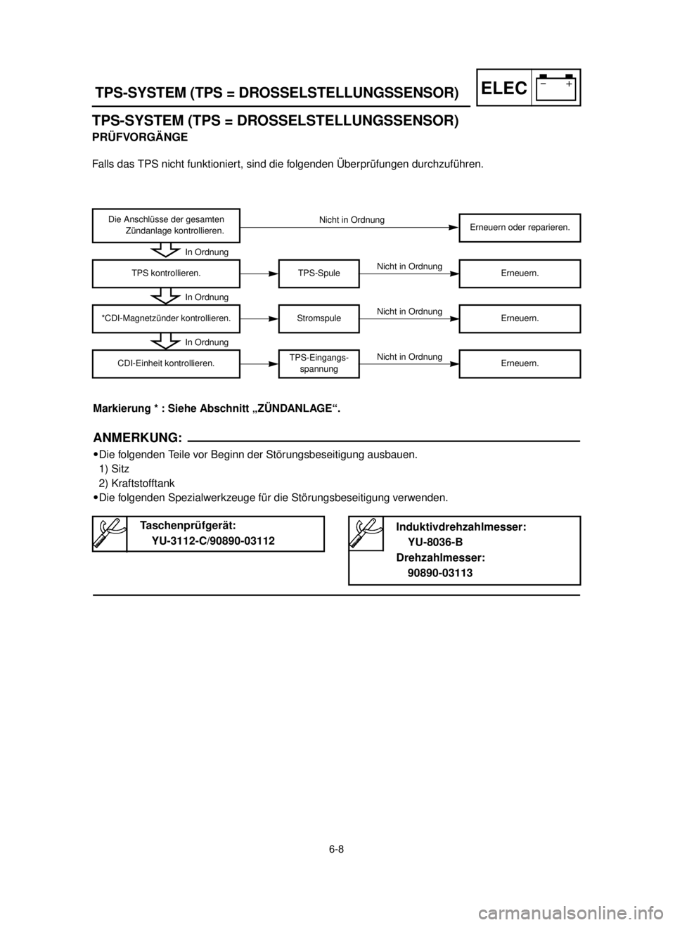
Markierung * : Siehe Abschnitt „ZÜNDANLAGE“.
ANMERKUNG:
9Die folgenden Teile vor Beginn der Störungsbeseitigung ausbauen.
1) Sitz
2) Kraftstofftank
9Die folgenden Spezialwerkzeuge für die Störungsbeseitigung verwenden.
Induktivdrehzahlmesser:
YU-8036-B
Drehzahlmesser:
90890-03113Taschenprüfgerät:
YU-3112-C/90890-03112
In Ordnung
In Ordnung
Stromspule
Nicht in Ordnung*CDI-Magnetzünder kontrollieren.Erneuern.
In Ordnung
TPS-Eingangs-
spannung
Nicht in OrdnungCDI-Einheit kontrollieren.Erneuern.
TPS-SYSTEM (TPS = DROSSELSTELLUNGSSENSOR)
PRÜFVORGÄNGE
Falls das TPS nicht funktioniert, sind die folgenden Überprüfungen durchzuführen.
5MW-9-30-6 7/6/00 1:38 PM Page 22
Page 511 of 578
6-8
SISTEMA TPS (SENSORE DI POSIZIONE
DELL’ACCELERATORE)
ELEC
Bobina del TPS
Ripararlo o sostituirlo.Controllare il collegamento dell’intero
sistema di accensione.
Non funziona
Non funziona
Non funziona
Non funzionaControllare il TPS.Sostituirla.
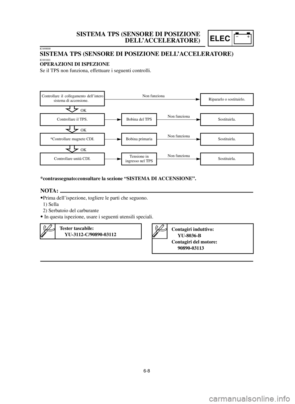
*contrassegnato:consultare la sezione “SISTEMA DI ACCENSIONE”.
NOTA:
9Prima dell’ispezione, togliere le parti che seguono.
1) Sella
2) Serbatoio del carburante
9In questa ispezione, usare i seguenti utensili speciali.
Contagiri induttivo:
YU-8036-B
Contagiri del motore:
90890-03113Tester tascabile:
YU-3112-C/90890-03112
OK
OK
Bobina primaria
*Controllare magnete CDI.Sostituirla.
OK
Tensione in
ingresso nel TPS
Controllare unità CDI.Sostituirla.
IC690000
SISTEMA TPS (SENSORE DI POSIZIONE DELL’ACCELERATORE)
IC691001
OPERAZIONI DI ISPEZIONE
Se il TPS non funziona, effettuare i seguenti controlli.
5MW-9-30-6 7/6/00 1:38 PM Page 23
Page 512 of 578
6-9
TPS (THROTTLE POSITION SENSOR) SYSTEMELEC
EC624000
COUPLERS AND LEADS CONNECTION
INSPECTION
1. Check:
9Couplers and leads connection
Rust/ Dust/ Looseness/Short-circuit Õ
Repair or replace.
EC692000
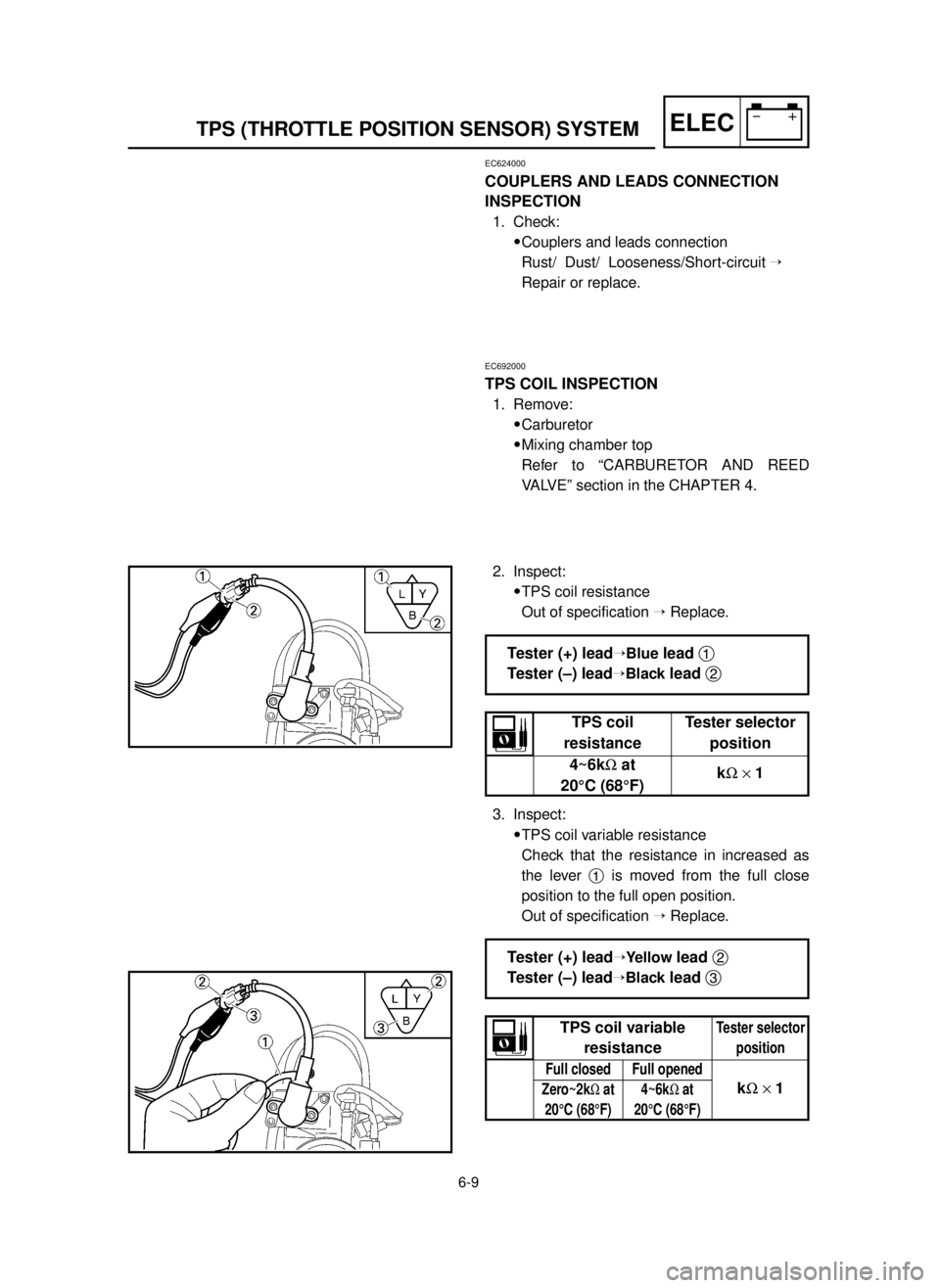
TPS COIL INSPECTION
1. Remove:
9Carburetor
9Mixing chamber top
Refer to “CARBURETOR AND REED
VALVE” section in the CHAPTER 4.
2. Inspect:
9TPS coil resistance
Out of specification ÕReplace.
3. Inspect:
9TPS coil variable resistance
Check that the resistance in increased as
the lever 1is moved from the full close
position to the full open position.
Out of specification ÕReplace.
Tester (+) leadÕBluelead 1
Tester (–) lead
ÕBlacklead 2
TPS coil Tester selector
resistance position
4~6k½at
k½´1
20°C (68°F)
Tester (+) leadÕYellowlead 2
Tester (–) lead
ÕBlacklead 3
Tester selector
positionTPS coil variable
resistance
Full closed Full opened
Zero~2k½at 4~6k½at
20°C (68°F) 20°C (68°F)
k½´1
5MW-9-30-6 7/6/00 1:38 PM Page 24
Page 513 of 578

6-9
SYSTEME TPS (CAPTEUR DE POSITION DU PAPILLON)
TPS-SYSTEM (TPS = DROSSELSTELLUNGSSENSOR)
SISTEMA TPS (SENSORE DI POSIZIONE DELL’ACCELERATORE)ELEC
VERIFICATION DE CONNEXION
DES COUPLEURS ET FILS
1. Contrôler:
9Connexion des coupleurs et fils
Rouille/poussière/desserré/court
-circuit
Õ
Réparer ou changer.
INSPEKTION DES ANSCHLUSSES
DER KUPPLUNGEN UND KABEL
1. Kontrollieren:
9Anschluß deren Kupplungen
und Kabel
Rost/Staub/Lockerheit/Kurz-
schlußÕReparieren oder
erneuern.IC624000
ISPEZIONE DEL
COLLEGAMENTO DI
ACCOPPIATORI E CONDUTTORI
1. Controllare:
9Collegamento di accoppiatori e
conduttori
Ruggine/Polvere/Allentamen-
to/Cortocircuito ÕRipararli o
sostituirli.
INSPECTION DE LA BOBINE DU
TPS
1. Déposer:
9Carburateur
9Haut de chambre de mélange
Se reporter à la section “CAR-
BURATEUR ET SOUPAPE
FLEXIBLE”.
TPS-SPULENINSPEKTION
1. Ausbauen:
9Vergaser
9Mischkammer-Oberteil
Siehe Abschnitt „VERGASER
UND ZUNGENVENTIL“.IC692000
ISPEZIONE DELLA BOBINA DEL
TPS
1. Togliere:
9Carburatore
9Parte superiore del diffusore
Consultare la sezione “CARBU-
RATORE E VALVOLA A LA
MELLA”.
2. Examiner:
9Résistance de la bobine du TPS
Hors spécification
ÕChanger.
3. Examiner:
9Résistance variable de la bobine
du TPS
Vérifier si la résistance augmen-
te lorsque le levier 1est dépla-
cé de la position de fermeture
complète à la position d’ouver-
ture complète.
Hors spécification
ÕChanger.
2. Prüfen:
9TPS-Spulenwiderstand
Abweichung von Spezifikation
ÕErneuern.
3. Prüfen:
9Regelbarer TPS-Spulenwider-
stand
Prüfen ob der Widerstand sich
erhöht wenn der Hebel 1vom
vollständig geschlossenen
Stand in den vollständig geöff-
neten Stand bewegt wird.
Abweichung von Spezifikation
ÕErneuern.2. Ispezionare:
9Resistenza della bobina del TPS
Fuori specifica ÕSostituirla.
3. Ispezionare:
9Resistenza variabile della bobi-
na del TPS
Controllare che la resistenza
aumenti quando la leva 1viene
spostata dalla posizione tutto
chiuso a quella tutto aperto.
Fuori specifica ÕSostituirla. Resistenza
Posizione del della bobina selettore del
del TPS tester
4~6k½a
k½´ 1
20°C (68°F)
Conduttore (+) del tester Õ
Conduttore Blu 1
Conduttore (–) del tester Õ
Conduttore nero 2
Résistance Position de
de la bobine sélecteur de
du TPS testeur
4~6k½à
k½´1
20°C (68°F)
Fil (+) de testeurÕFil bleu 1
Fil (–) de testeurÕFil noir 2Positives (+) Kabel des PrüfgerätesÕ
Blau Kabel 1
Negatives (–) Kabel des PrüfgerätesÕ
Schwarz Kabel 2
TPS- Position des
Spulen-Wahlschalterswiderstand am Prüfgerät
4~6k½bei
k½´ 1
20°C (68°F)
Resistenza variabile Posizionedella bobina del selettoredel TPSdel tester
Completa- Completa-
mente chiuso mente aperto
Zero~2k½a 4~6k½ak½´ 1
20°C (68°F) 20°C (68°F)
Conduttore (+) del testerÕ
Conduttore Giallo 2
Conduttore (–) del testerÕ
Conduttore Nero 3Fil (+) de testeurÕ
Fil janne 2
Fil (–) de testeurÕ
Fil noir 3
Résistance Position de
variable de la sélecteur
bobine du TPS de testeur
Fermeture Ouverture
complète complète
Zéro~2k½à4~6k½àk½´120°C (68°F)20°C (68°F)
Positives (+) Kabel des PrüfgerätesÕ
Gelb Kabel 2
Negatives (–) Kabel des PrüfgeräteÕ
Schwarz Kabel 3
Regelbarer Position des TPS-Spulenwider-Wahlschalters standam Prüfgerät
VollständigVollständig geschlossengeöffnet
Null~2k½bei4~6k½beik½´ 120°C (68°F)20°C (68°F)
5MW-9-30-6 7/6/00 1:38 PM Page 25
Page 514 of 578

6-10
TPS (THROTTLE POSITION SENSOR) SYSTEMELEC
EC693000
TPS REPLACEMENT AND ADJUSTMENT
1. Remove:
9Carburetor
9Mixing chamber top
Refer to “CARBURETOR AND REED
VALVE” section in the CHAPTER 4.
2. Remove:
9Screw (TPS) 1
9Plain washer 2
9TPS 3
NOTE:
Loosen the screws using the T20 bit (tamper
resistant fastener type).
3. Replace:
9TPS
4. Install:
9TPS 1
9Plain washer 2
9Screw (TPS) 3
NOTE:
9Align the slot ain the TPS with the projection
bon the carburetor.
9Temporarily tighten the screws (TPS).
5. Install:
9Mixing chamber top
9Carburetor
Refer to “CARBURETOR AND REED
VALVE” section in the CHAPTER 4.
6. Start the engine and thoroughly warm it up.
5MW-9-30-6 7/6/00 1:39 PM Page 26