fuel YAMAHA YZ250LC 2003 Betriebsanleitungen (in German)
[x] Cancel search | Manufacturer: YAMAHA, Model Year: 2003, Model line: YZ250LC, Model: YAMAHA YZ250LC 2003Pages: 586, PDF-Größe: 14.75 MB
Page 214 of 586

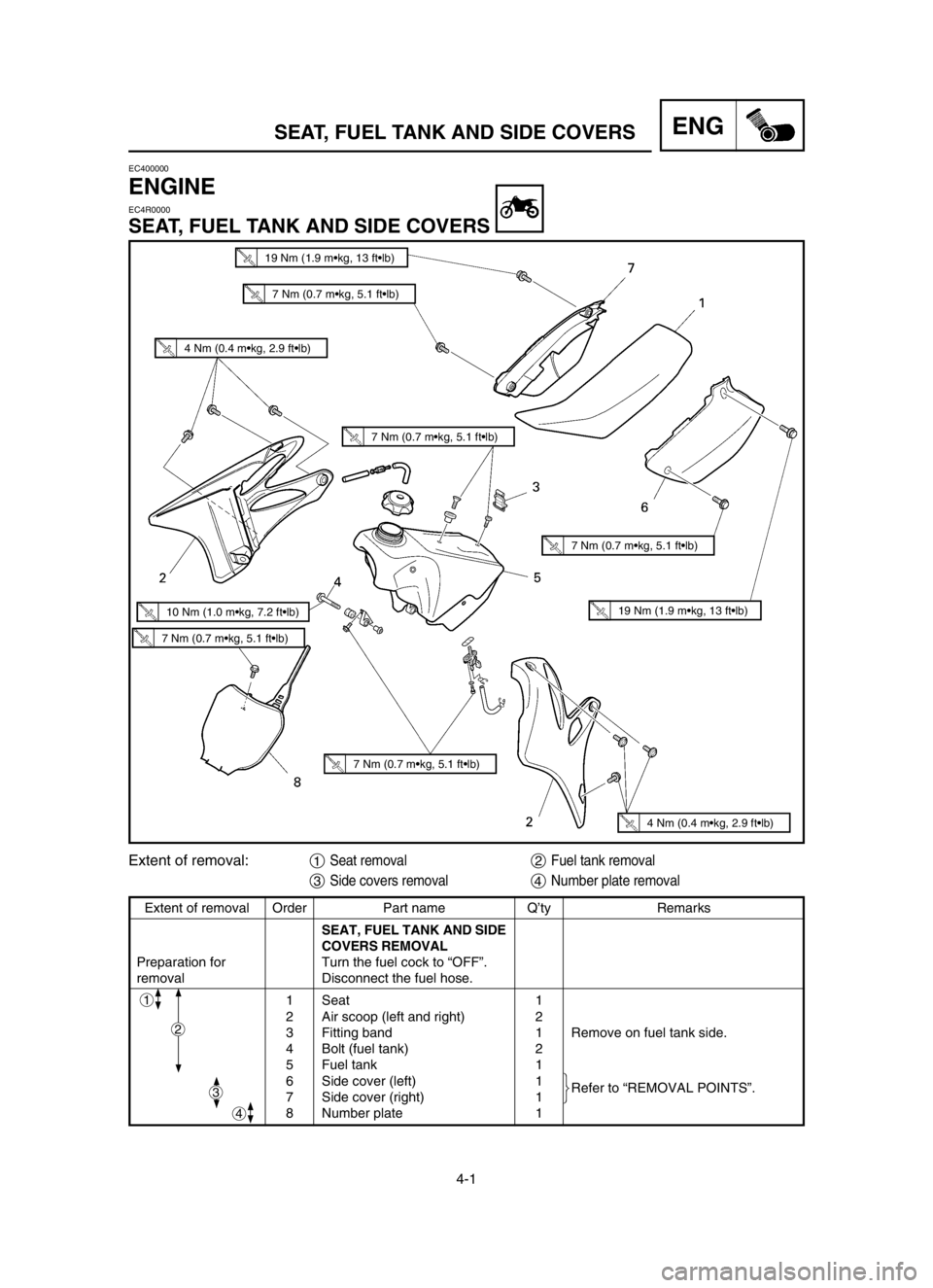
4-1
SEAT, FUEL TANK AND SIDE COVERSENG
EC400000
ENGINE
EC4R0000
SEAT, FUEL TANK AND SIDE COVERS
Extent of removal Order Part name Q’ty Remarks
SEAT, FUEL TANK AND SIDE
COVERS REMOVAL
Preparation for Turn the fuel cock to “OFF”.
removal Disconnect the fuel hose.
1 Seat 1
2 Air scoop (left and right) 2
3 Fitting band 1 Remove on fuel tank side.
4 Bolt (fuel tank) 2
5 Fuel tank 1
6 Side cover (left) 1
Refer to “REMOVAL POINTS”.
7 Side cover (right) 1
8 Number plate 1
1
4
Extent of removal:1Seat removal2Fuel tank removal
3Side covers removal4Number plate removal
2
3
7 Nm (0.7 m•kg, 5.1 ft•lb)
4 Nm (0.4 m•kg, 2.9 ft•lb)
4 Nm (0.4 m•kg, 2.9 ft•lb)
7 Nm (0.7 m•kg, 5.1 ft•lb)
7 Nm (0.7 m•kg, 5.1 ft•lb)
7 Nm (0.7 m•kg, 5.1 ft•lb)
10 Nm (1.0 m•kg, 7.2 ft•lb)
7 Nm (0.7 m•kg, 5.1 ft•lb)
19 Nm (1.9 m•kg, 13 ft•lb)
19 Nm (1.9 m•kg, 13 ft•lb)
5UP-9-30-4A 5/24/02 5:27 PM Page 2
Page 216 of 586

4-2
ENGSEAT, FUEL TANK AND SIDE COVERS
EC4R3000
REMOVAL POINTS
EC413110
Side cover
1. Remove:
9Bolt (side cover)
9Side cover (left and right) 1
NOTE:
Draw the side cover downward to remove it
because its claws aare inserted in the air
cleaner case.
5UP-9-30-4A 5/24/02 5:27 PM Page 4
Page 218 of 586

4-3
EXHAUST PIPE AND SILENCERENG
EC4S0000
EXHAUST PIPE AND SILENCER
Extent of removal:1Silencer removal2Exhaust pipe removal
11 Nm (1.1 m•kg, 8.0 ft•lb)
12 Nm (1.2 m•kg, 8.7 ft•lb)
10 Nm (1.0 m•kg, 7.2 ft•lb)
25 Nm (2.5 m•kg, 18 ft•lb)
12 Nm (1.2 m•kg, 8.7 ft•lb)
14 Nm (1.4 m•kg, 10 ft•lb)
Extent of removal Order Part name Q’ty Remarks
EXHAUST PIPE AND
SILENCER REMOVAL
Preparation for Side cover (right) Refer to “SEAT, FUEL TANK AND
removal SIDE COVERS” section.
1 Bolt (silencer) 2
2 Silencer 1
3 Collar [D=ø10.5 mm (0.41 in)] 1
4 Collar [D=ø10.0 mm (0.39 in)] 1
5 Grommet (front) 1
6 Grommet (rear) 1
7 Tension spring 2
8 Bolt (exhaust pipe) 2
9 Exhaust pipe 1
1
2
2
5UP-9-30-4A 5/24/02 5:27 PM Page 6
Page 220 of 586

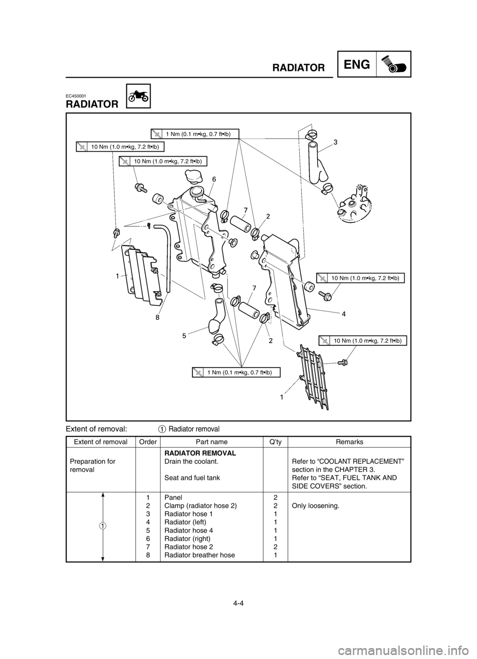
4-4
RADIATORENG
Extent of removal Order Part name Q’ty Remarks
RADIATOR REMOVAL
Preparation for Drain the coolant.
Refer to “COOLANT REPLACEMENT”
removal section in the CHAPTER 3.
Seat and fuel tank Refer to “SEAT, FUEL TANK AND
SIDE COVERS” section.
1 Panel 2
2 Clamp (radiator hose 2) 2 Only loosening.
3 Radiator hose 1 1
4 Radiator (left) 1
5 Radiator hose 4 1
6 Radiator (right) 1
7 Radiator hose 2 2
8 Radiator breather hose 1
EC450001
RADIATOR
Extent of removal:1Radiator removal
1
1 Nm (0.1 m•kg, 0.7 ft•lb)
10 Nm (1.0 m•kg, 7.2 ft•lb)
1 Nm (0.1 m•kg, 0.7 ft•lb)
10 Nm (1.0 m•kg, 7.2 ft•lb)
10 Nm (1.0 m•kg, 7.2 ft•lb)
10 Nm (1.0 m•kg, 7.2 ft•lb)
5UP-9-30-4A 5/24/02 5:27 PM Page 8
Page 226 of 586

4-7
CARBURETOR AND REED VALVEENG
EC460000
CARBURETOR AND REED VALVE
Extent of removal Order Part name Q’ty Remarks
CARBURETOR AND
REED VALVE REMOVAL
Preparation for Fuel tank Refer to “SEAT, FUEL TANK AND
removal SIDE COVERS” section.
1 Solenoid valve lead 1 Disconnect the solenoid valve lead.
2 TPS (throttle position sensor) 1 Disconnect the TPS
lead (throttle position sensor) lead.
3 Clamp (carburetor joint) 2
Loosen the screws (carburetor joint).
4 Carburetor 1
5 Carburetor joint 1
6 Reed valve assembly 1
7 Stopper (reed valve) 2
8 Reed valve 2
9 Plate (reed valve) 1
1
Extent of removal:1Carburetor removal2Reed valve removal
10 Nm (1.0 m•kg, 7.2 ft•lb)
1 Nm (0.1 m•kg, 0.7 ft•lb)
2
5UP-9-30-4A 5/24/02 5:27 PM Page 14
Page 230 of 586

4-9
ENGCARBURETOR AND REED VALVE
EC466020
HANDLING NOTE
cC
Do not loosen the screws {TPS (throttle
position sensor)} except when changing
the TPS (throttle position sensor) due to
failure because it will cause a drop in
engine performance.
EC463000
REMOVAL POINTS
EC463110
Throttle valve
1. Remove:
9Throttle valve 1
9Ring 2
9Spring (throttle valve) 3
9Mixing chamber top 4
9Throttle cable 5
NOTE:
While compressing the spring (throttle valve),
disconnect the throttle cable.
EC463401
Pilot air screw
1. Remove:
9Pilot air screw 1
NOTE:
To optimize the fuel flow at a smaller throttle
opening, each machine’s pilot air screw has
been individually set at the factory. Before
removing the pilot air screw, turn it in fully and
count the number of turns. Record this number
as the factory-set number of turns out.
5UP-9-30-4A 5/24/02 5:27 PM Page 18
Page 248 of 586

4-18
CYLINDER HEAD, CYLINDER AND PISTONENG
EC470000
CYLINDER HEAD, CYLINDER AND PISTONEC478000
CYLINDER HEAD AND CYLINDER
Extent of removal Order Part name Q’ty Remarks
CYLINDER HEAD AND
CYLINDER REMOVAL
Preparation for Seat and fuel tank Refer to “SEAT, FUEL TANK AND
removal SIDE COVERS” section.
Exhaust pipe and silencer Refer to ”EXHAUST PIPE AND
SILENCER” section.
Radiator hose 1 Disconnect at cylinder head side.
Carburetor Refer to “CARBURETOR AND REED
VALVE” section.
1 Spark plug 1
2 Engine bracket 2
3 Nut (cylinder head) 6
Loosen each nut 1/4 turn, and remove
them after all nuts are loosened.
4 Cylinder head 1
5 Power valve housing 1
6 Push rod 1 Refer to “REMOVAL POINTS”.
7 Nut (cylinder) 4
8 Cylinder 1
Extent of removal:1Cylinder head removal2Cylinder removal
1
2
34 Nm (3.4 m•kg, 24 ft•lb)
69 Nm (6.9 m•kg, 50 ft•lb)
20 Nm (2.0 m•kg, 14 ft•lb)
5 Nm (0.5 m•kg, 3.6 ft•lb)
5 Nm (0.5 m•kg, 3.6 ft•lb)
25 Nm (2.5 m•kg, 18 ft•lb)
10 Nm (1.0 m•kg, 7.2 ft•lb)
42 Nm (4.2 m•kg, 30 ft•lb)
10 Nm (1.0 m•kg, 7.2 ft•lb)
5UP-9-30-4A 5/24/02 5:27 PM Page 36
Page 324 of 586

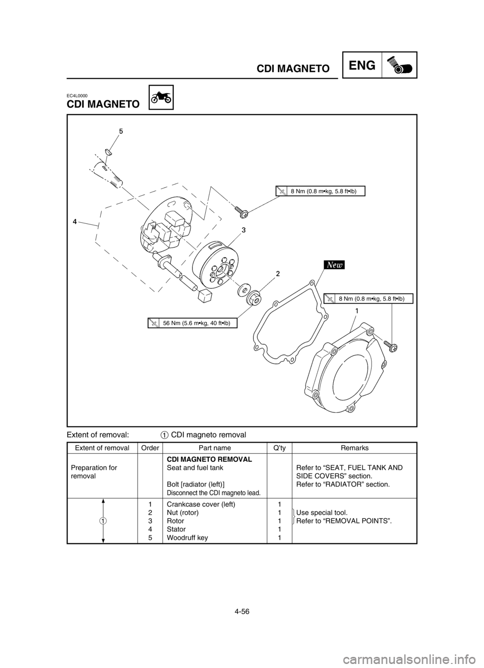
4-56
CDI MAGNETOENG
Extent of removal Order Part name Q’ty Remarks
CDI MAGNETO REMOVAL
Preparation for Seat and fuel tank Refer to “SEAT, FUEL TANK AND
removal SIDE COVERS” section.
Bolt [radiator (left)] Refer to “RADIATOR” section.
Disconnect the CDI magneto lead.
1 Crankcase cover (left) 1
2 Nut (rotor) 1 Use special tool.
3 Rotor 1 Refer to “REMOVAL POINTS”.
4 Stator 1
5 Woodruff key 1
EC4L0000
CDI MAGNETO
1
Extent of removal:1CDI magneto removal
8 Nm (0.8 m•kg, 5.8 ft•lb)
8 Nm (0.8 m•kg, 5.8 ft•lb)
56 Nm (5.6 m•kg, 40 ft•lb)
5UP-9-30-4C 5/24/02 5:32 PM Page 14
Page 332 of 586

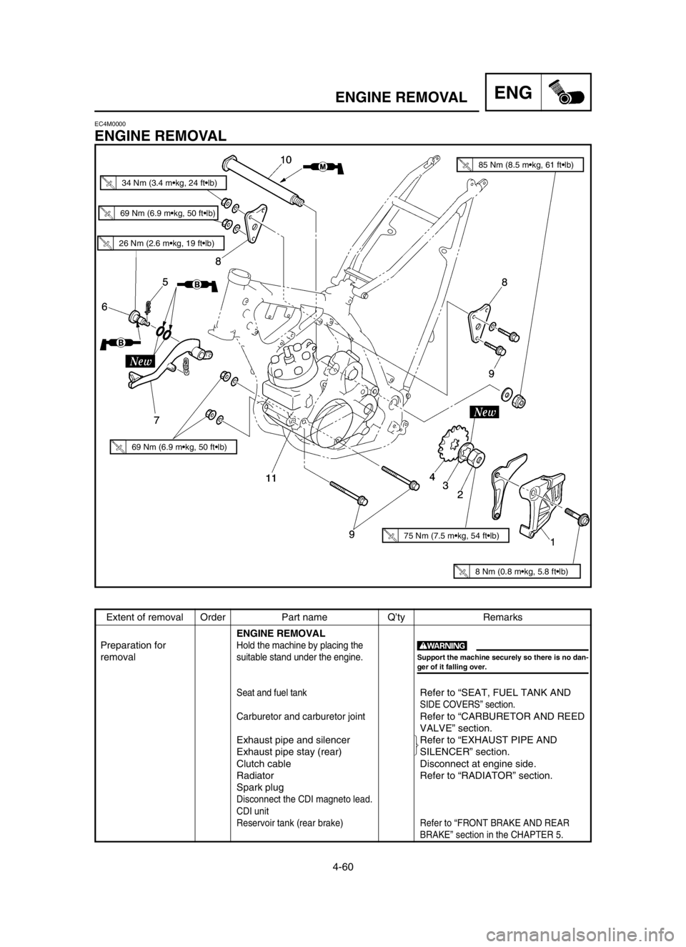
4-60
ENGINE REMOVALENG
Extent of removal Order Part name Q’ty Remarks
ENGINE REMOVAL
Preparation for
Hold the machine by placing the
removalsuitable stand under the engine.
Seat and fuel tankRefer to “SEAT, FUEL TANK AND
SIDE COVERS” section.
Carburetor and carburetor jointRefer to “CARBURETOR AND REED
VALVE” section.
Exhaust pipe and silencer Refer to “EXHAUST PIPE AND
Exhaust pipe stay (rear) SILENCER” section.
Clutch cable Disconnect at engine side.
Radiator Refer to “RADIATOR” section.
Spark plug
Disconnect the CDI magneto lead.
CDI unit
Reservoir tank (rear brake) Refer to “FRONT BRAKE AND REAR
BRAKE” section in the CHAPTER 5.
EC4M0000
ENGINE REMOVAL
w
Support the machine securely so there is no dan-
ger of it falling over.
26 Nm (2.6 m•kg, 19 ft•lb)
69 Nm (6.9 m•kg, 50 ft•lb)
69 Nm (6.9 m•kg, 50 ft•lb)
75 Nm (7.5 m•kg, 54 ft•lb)
8 Nm (0.8 m•kg, 5.8 ft•lb)
85 Nm (8.5 m•kg, 61 ft•lb)
34 Nm (3.4 m•kg, 24 ft•lb)
5UP-9-30-4C 5/24/02 5:33 PM Page 22
Page 454 of 586

5-45
CHASHANDLEBAR
14. Clamp the clamp portion aof the number
plate to the handlebar.
15. Insert the end of the fuel breather hose 1
into the hole of the number plate.
5UP-9-30-5CN 5/24/02 5:56 PM Page 14