engine YAMAHA YZ250LC 2005 Notices Demploi (in French)
[x] Cancel search | Manufacturer: YAMAHA, Model Year: 2005, Model line: YZ250LC, Model: YAMAHA YZ250LC 2005Pages: 596, PDF Size: 12.55 MB
Page 58 of 596

1-15
STARTING AND BREAK-IN
GEN
INFO
cC
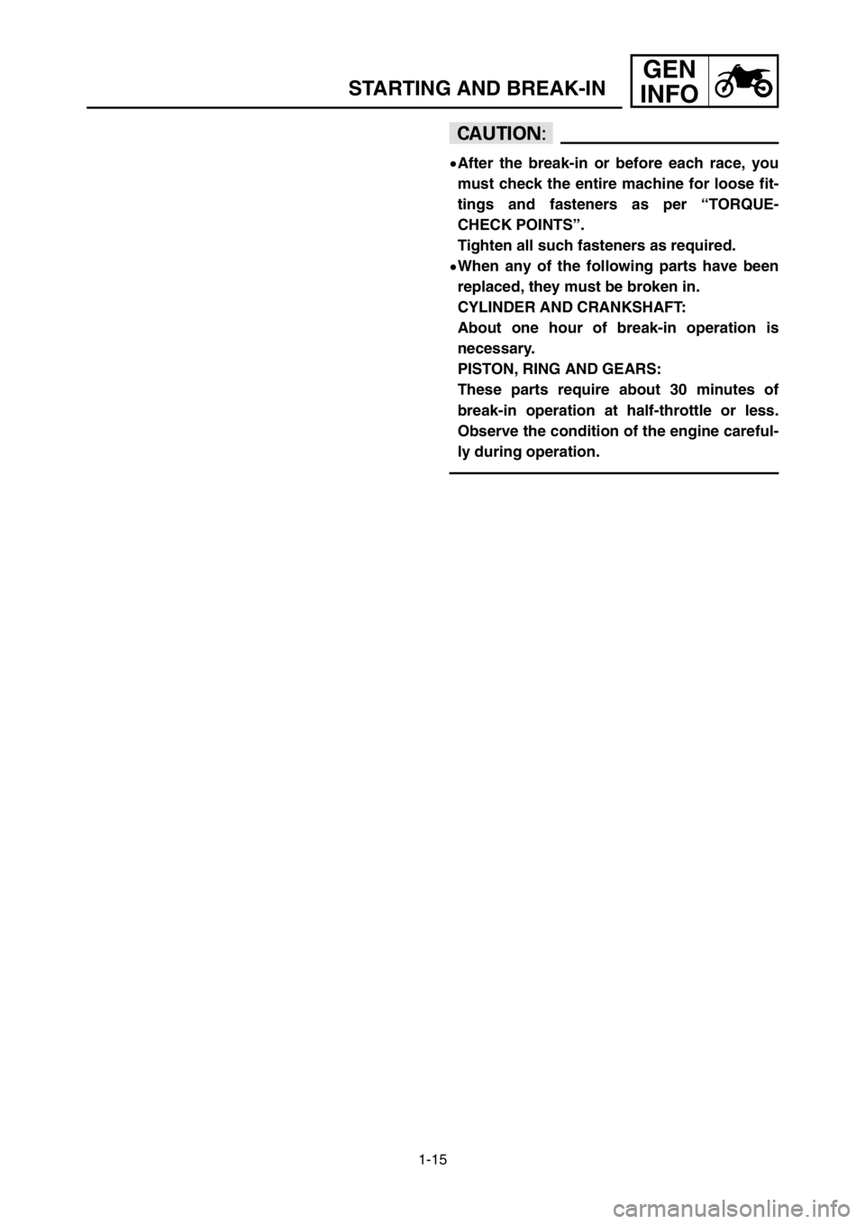
9After the break-in or before each race, you
must check the entire machine for loose fit-
tings and fasteners as per “TORQUE-
CHECK POINTS”.
Tighten all such fasteners as required.
9When any of the following parts have been
replaced, they must be broken in.
CYLINDER AND CRANKSHAFT:
About one hour of break-in operation is
necessary.
PISTON, RING AND GEARS:
These parts require about 30 minutes of
break-in operation at half-throttle or less.
Observe the condition of the engine careful-
ly during operation.
1P8-9-30-1 19/5/04 9:00 AM Page 34
Page 60 of 596

1-16
TORQUE-CHECK POINTS
GEN
INFO
EC1A0013
TORQUE-CHECK POINTS
Frame construction Frame to rear frame
Combined seat and tank Fuel tank to frame
Engine mounting Frame to engine
Engine bracket to engine
Engine bracket to frame
Steering Steering shaft to Steering shaft to frame
handlebar Steering shaft to handle crown
Handle crown to handlebar
Suspension Front Steering shaft to Front fork to handle crown
front fork Front fork to under bracket
Rear For link type Assembly of links
Link to frame
Link to shock absorber
Link to swingarm
Rear Installation of shock Shock absorber to frame
absorber
Rear Installation of swingarm Tightening of pivot shaft
Wheel Installation of wheel Front Tightening of front axle
Tightening of axle holder
Rear Tightening of rear axle
Wheel to sprocket
Brake Front Caliper to front fork
Brake disc to wheel
Tightening of union bolt
Master cylinder to handlebar
Tightening of air bleeder
Tightening of brake hose holder
Rear Brake pedal to frame
Brake disc to wheel
Tighening of union bolt
Master cylinder to frame
Tightening of air bleeder
Tightening of brake hose holder
Fuel system Fuel tank to fuel cock
NOTE:
Concerning the tightening torque, refer to “
MAINTENANCE SPECIFICATIONS” section in
the CHAPTER 2.
1P8-9-30-1 19/5/04 9:00 AM Page 36
Page 64 of 596

1-17
CLEANING AND STORAGE
GEN
INFO
EC1B0000
CLEANING AND STORAGE
EC1B1000
CLEANING
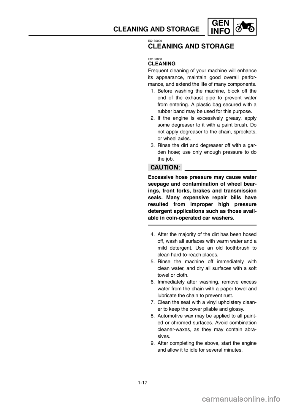
Frequent cleaning of your machine will enhance
its appearance, maintain good overall perfor-
mance, and extend the life of many components.
1. Before washing the machine, block off the
end of the exhaust pipe to prevent water
from entering. A plastic bag secured with a
rubber band may be used for this purpose.
2. If the engine is excessively greasy, apply
some degreaser to it with a paint brush. Do
not apply degreaser to the chain, sprockets,
or wheel axles.
3. Rinse the dirt and degreaser off with a gar-
den hose; use only enough pressure to do
the job.
cC
Excessive hose pressure may cause water
seepage and contamination of wheel bear-
ings, front forks, brakes and transmission
seals. Many expensive repair bills have
resulted from improper high pressure
detergent applications such as those avail-
able in coin-operated car washers.
4. After the majority of the dirt has been hosed
off, wash all surfaces with warm water and a
mild detergent. Use an old toothbrush to
clean hard-to-reach places.
5. Rinse the machine off immediately with
clean water, and dry all surfaces with a soft
towel or cloth.
6. Immediately after washing, remove excess
water from the chain with a paper towel and
lubricate the chain to prevent rust.
7. Clean the seat with a vinyl upholstery clean-
er to keep the cover pliable and glossy.
8. Automotive wax may be applied to all paint-
ed or chromed surfaces. Avoid combination
cleaner-waxes, as they may contain abra-
sives.
9. After completing the above, start the engine
and allow it to idle for several minutes.
1P8-9-30-1 19/5/04 9:00 AM Page 40
Page 66 of 596

1-18
CLEANING AND STORAGE
GEN
INFO
EC1B2001
STORAGE
If your machine is to be stored for 60 days or
more, some preventive measures must be taken
to avoid deterioration. After cleaning the
machine thoroughly, prepare it for storage as fol-
lows:
1. Drain the fuel tank, fuel lines, and the carbu-
retor float bowl.
2. Remove the spark plug, pour a tablespoon
of SAE 10W-30 motor oil in the spark plug
hole, and reinstall the plug. With the engine
stop switch pushed in, kick the engine over
several times to coat the cylinder walls with
oil.
3. Remove the drive chain, clean it thoroughly
with solvent, and lubricate it. Reinstall the
chain or store it in a plastic bag tied to the
frame.
4. Lubricate all control cables.
5. Block the frame up to raise the wheels off
the ground.
6. Tie a plastic bag over the exhaust pipe out-
let to prevent moisture from entering.
7. If the machine is to be stored in a humid or
salt-air environment, coat all exposed metal
surfaces with a film of light oil. Do not apply
oil to rubber parts or the seat cover.
NOTE:
Make any necessary repairs before the machine
is stored.
1P8-9-30-1 19/5/04 9:00 AM Page 42
Page 68 of 596

2-1
GENERAL SPECIFICATIONSSPEC
Model name: YZ250T1 (USA, CDN)
YZ250 (EUROPE, ZA)
YZ250T (AUS, NZ)
Model code number: 1P81 (USA, CDN, ZA)
1P82 (EUROPE)
1P84 (AUS, NZ)
Dimensions:USA, ZAAUS, NZ EUROPE CDN
Overall length 2,179 mm←2,188 mm 2,186 mm
(85.8 in) (86.1 in) (86.1 in)
Overall width 827 mm←←←
(32.6 in)
Overall height 1,306 mm←1,310 mm 1,309 mm
(51.4 in) (51.6 in) (51.5 in)
Seat height 989 mm←992 mm←
(38.9 in) (39.1 in)
Wheelbase 1,481 mm←1,485 mm←
(58.3 in) (58.5 in)
Minimum ground clearance 383 mm←386 mm←
(15.1 in) (15.2 in)
Dry weight:
Without oil and fuel 96.0 kg (211.6 lb)
Engine:
Engine type Liquid cooled 2-stroke, gasoline
Cylinder arrangement Single cylinder, forward inclined
Displacement 249 cm
3(8.76 lmp oz, 8.42 US oz)
Bore ×Stroke 66.4 ×72 mm (2.614 ×2.835 in)
Compression ratio 9.1~10.9 : 1 (Expect for EUROPE)
9.0~10.6 : 1 (For EUROPE)
Starting system Kick starter
Lubrication system: Premix (30 : 1)(Yamalube 2-R)
Oil type or grade (2-Cycle):
Transmission oil Yamalube 4 (10W-30) or SAE 10W-30 type SE
motor oil
Periodic oil change 0.75 L (0.66 Imp qt, 0.79 US qt)
Total amount 0.80 L (0.70 Imp qt, 0.85 US qt)
Coolant capacity (including all routes): 1.20 L (1.06 Imp qt, 1.27 US qt)
Air filter: Wet type element
Fuel:
Type Premium unleaded gasoline
only with a research octane
number of 95 or higher
Tank capacity 8.0 L (1.76 Imp gal, 2.11 US gal)
EC200000
SPECIFICATIONSEC211000
GENERAL SPECIFICATIONS
1P8-9-30-2 19/5/04 9:08 AM Page 2
Page 70 of 596

2-3
MAINTENANCE SPECIFICATIONSSPEC
Item Standard Limit
Cylinder head:USA, CDN, ZA,
EUROPE
AUS, NZ
Combustion chamber capacity 21.0 cm
321.5 cm3…
(0.739 Imp oz, (0.757 Imp oz,
0.710 US oz) 0.727 US oz)
Warp limit……
0.03 mm (0.0012 in)
Cylinder:
Bore size 66.400~66.414 mm 66.5 mm (2.618 in)
(2.6142~2.6147 in)
Taper limit…
0.05 mm (0.0020 in)
Out of round limit…
0.01 mm (0.0004 in)
Piston:
Piston size/ 66.352~66.367 mm…
(2.6120~2.6129 in)
Measuring point* 17.5 mm (0.69 in)…
Piston clearance 0.045~0.050 mm 0.1 mm (0.004 in)
(0.0018~0.0020 in)
Piston offset 1.5 mm (0.059 in)/EX-side…
Piston pin:
Piston pin outside diameter 17.995~18.000 mm 17.975 mm
(0.7085~0.7087 in) (0.7077 in)
Piston ring:
Sectional sketch Plain…
B=1.0 mm (0.039 in)…
T=2.55 mm (0.100 in)…
End gap (installed) 0.40~0.55 mm (0.016~0.022 in) 0.95 mm (0.037 in)
Side clearance (installed) : 1st
0.030~0.065 mm (0.0012~0.0026 in)0.1 mm (0.004 in)
: 2nd0.030~0.065 mm (0.0012~0.0026 in)0.1 mm (0.004 in)
Crankshaft:
Crank width “A” 59.95~60.00 mm (2.360~2.362 in)…
Runout limit “C” 0.03 mm (0.0012 in) 0.05 mm (0.0020 in)
Connecting rod big end
side clearance “D” 0.25~0.75 mm (0.010~0.030 in)…
Small end free play “F” 0.4~1.0 mm (0.016~0.039 in) 2.0 mm (0.08 in)
Clutch:
Friction plate thickness 2.9~3.1 mm (0.114~0.122 in) 2.8 mm (0.110 in)
Quantity 8 …
Clutch plate thickness 1.5~1.7 mm (0.059~0.067 in) …
Quantity 7 …
Warp limit … 0.2 mm (0.008 in)
Clutch spring free length 50.0 mm (1.969 in) 48.0 mm (1.890 in)
Quantity 6 …
EC212000
MAINTENANCE SPECIFICATIONSEC212100
ENGINE
1P8-9-30-2 19/5/04 9:08 AM Page 4
Page 77 of 596

2-10
MAINTENANCE SPECIFICATIONSSPEC
M 4 × 0.7
M10 × 1.25
M10 × 1.25
M20 × 1.5
M 8 × 1.25
–
M 6 × 1.0
M 6 × 1.0
M 8 × 1.25
M 8 × 1.25
M10 × 1.25
M10 × 1.25
M10 × 1.25
M16 × 1.5
M14 × 1.5
M14 × 1.5
M14 × 1.5
M10 × 1.25
M10 × 1.25
M 8 × 1.25
M 8 × 1.25
M 5 ×0.8
M 4 ×0.7
M 8 × 1.25
M 6 × 1.0
M 5 ×0.8
M 5 ×0.8
M10 × 1.25
M 6 × 1.0
M 6 × 1.0
M 6 × 1.0
M 6 × 1.0
M 6 × 1.0
M 8 × 1.25
M 6 × 1.0
M 6 × 1.0
M 6 × 1.0
M 6 × 1.0
M 6 × 1.0
M 6 × 1.0
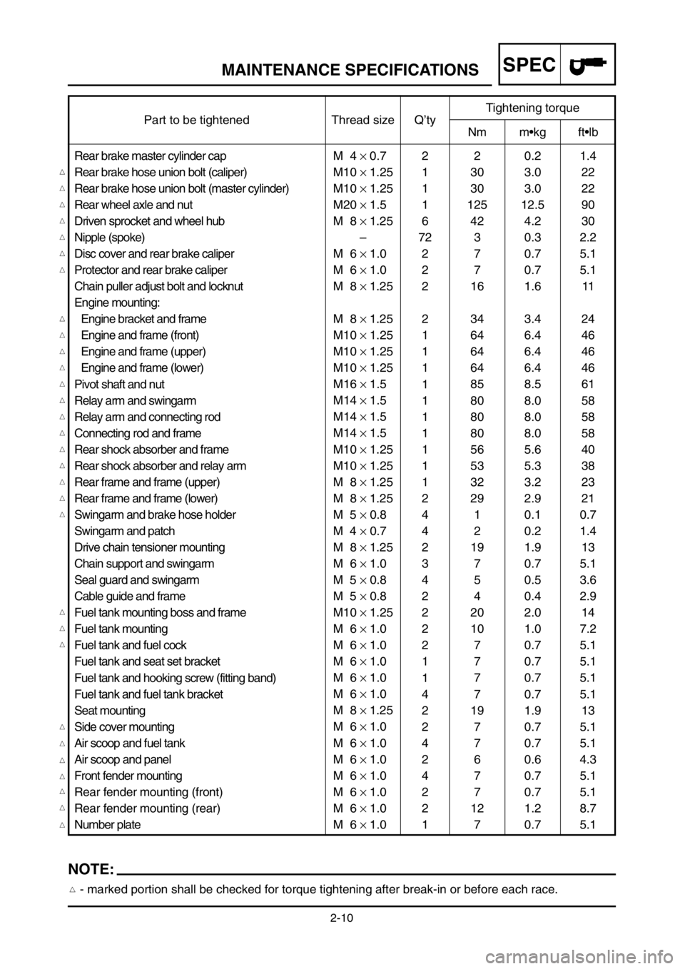
M 6 × 1.0 Rear brake master cylinder cap
Rear brake hose union bolt (caliper)
Rear brake hose union bolt (master cylinder)
Rear wheel axle and nut
Driven sprocket and wheel hub
Nipple (spoke)
Disc cover and rear brake caliper
Protector and rear brake caliper
Chain puller adjust bolt and locknut
Engine mounting:
Engine bracket and frame
Engine and frame (front)
Engine and frame (upper)
Engine and frame (lower)
Pivot shaft and nut
Relay arm and swingarm
Relay arm and connecting rod
Connecting rod and frame
Rear shock absorber and frame
Rear shock absorber and relay arm
Rear frame and frame (upper)
Rear frame and frame (lower)
Swingarm and brake hose holder
Swingarm and patch
Drive chain tensioner mounting
Chain support and swingarm
Seal guard and swingarm
Cable guide and frame
Fuel tank mounting boss and frame
Fuel tank mounting
Fuel tank and fuel cock
Fuel tank and seat set bracket
Fuel tank and hooking screw (fitting band)
Fuel tank and fuel tank bracket
Seat mounting
Side cover mounting
Air scoop and fuel tank
Air scoop and panel
Front fender mounting
Rear fender mounting (front)
Rear fender mounting (rear)
Number platePart to be tightened Thread size Q’tyTightening torque
Nm m•kg ft•lb
2
1
1
1
6
72
2
2
2
2
1
1
1
1
1
1
1
1
1
1
2
4
4
2
3
4
2
2
2
2
1
1
4
2
2
4
2
4
2
2
12
30
30
125
42
3
7
7
16
34
64
64
64
85
80
80
80
56
53
32
29
1
2
19
7
5
4
20
10
7
7
7
7
19
7
7
6
7
7
12
70.2
3.0
3.0
12.5
4.2
0.3
0.7
0.7
1.6
3.4
6.4
6.4
6.4
8.5
8.0
8.0
8.0
5.6
5.3
3.2
2.9
0.1
0.2
1.9
0.7
0.5
0.4
2.0
1.0
0.7
0.7
0.7
0.7
1.9
0.7
0.7
0.6
0.7
0.7
1.2
0.71.4
22
22
90
30
2.2
5.1
5.1
11
24
46
46
46
61
58
58
58
40
38
23
21
0.7
1.4
13
5.1
3.6
2.9
14
7.2
5.1
5.1
5.1
5.1
13
5.1
5.1
4.3
5.1
5.1
8.7
5.1
NOTE:
- marked portion shall be checked for torque tightening after break-in or before each race.
1P8-9-30-2 19/5/04 9:08 AM Page 11
Page 80 of 596

2-13
GENERAL TORQUE SPECIFICATIONS/
DEFINITION OF UNITS
SPEC
This chart specifies torque for standard faste-
ners with standard I.S.O. pitch threads. Torque
specifications for special components or assem-
blies are included in the applicable sections of
this book. To avoid warpage, tighten multi-faste-
ner assemblies in a crisscross fashion, in pro-
gressive stages, until full torque is reached.
Unless otherwise specified, torque specifications
call for clean, dry threads. Components should
be at room temperature.
A: Distance across flats
B: Outside thread diameter
EC230000
DEFINITION OF UNITS
EC220001
GENERAL TORQUE SPECIFICATIONS
ABTORQUE SPECIFICATION
(Nut) (Bolt)
Nm m•kg ft•lb
10 mm 6 mm 6 0.6 4.3
12 mm 8 mm 15 1.5 11
14 mm 10 mm 30 3.0 22
17 mm 12 mm 55 5.5 40
19 mm 14 mm 85 8.5 61
22 mm 16 mm 130 13 94
Unit Read Definition Measure
mm milimeter 10-
3meter Length
cm centimeter 10-2meter Length
kg kilogram 103gram Weight
N Newton 1 kg ×m/sec2Force
Nm Newton meter N ×m Torque
m•kg Meter kilogrma m ×kg Torque
Pa Pascal N/m2Pressure
N/mm Newton per millimeter N/mm Spring rate
L Liter — Volume or capacity
cm3Cubic centimeter — Volume or capacity
r/min Revolution per minute — Engine speed
1P8-9-30-2 19/5/04 9:08 AM Page 14
Page 120 of 596

2-14
CABLE ROUTING DIAGRAMSPEC
EC240000
CABLE ROUTING DIAGRAM
1Radiator hose
2Throttle cable
3Clutch cable
4“ENGINE STOP” button lead
5Radiator breather hose
6C.D.I. magneto lead
7Ignition coil leadAPass the clutch cable on the out-
side of the throttle cable and
“ENGINE STOP” button lead.
BPass through the cable guide the
throttle cable, “ENGINE STOP”
button lead and clutch cable.
CAlign the throttle cable locating
tape with the cable guide.
DPass above the radiator hose the
throttle cable, “ENGINE STOP”
button lead and clutch cable.
EClamp the “ENGINE STOP” but-
ton lead to the frame.
FClamp to the frame the throttle
cable, clutch cable, TPS (throttle
position sensor) lead and sole-
noid valve lead.
GClamp to the frame the throttle
cable, TPS (throttle position sen-
sor) lead and solenoid valve
lead.HPass the clutch cable in front of
the center of the cylinder head
tightening nut.
IPass the air vent hose, overflow
hose and crankcase breather
hose between the frame and
connecting rod.
JLocate the clamp ends in the
arrowed range.
1P8-9-30-2 16/6/04 11:47 AM Page 54
Page 121 of 596

2-14
SCHEMA DE CHEMINEMENT DES CABLES
KABELFÜHRUNGSÜBERSICHTPLAN
DIAGRAMMA DEL PASSAGGIO DEI CAVISPEC
KABELFÜHRUNGSÜBER-
SICHTPLAN
1Kühlerschlauch
2Gaszug
3Kupplungszug
4„ENGINE STOP“-Schalterkabel
5Kühler-Entlüftungsschlauch
6CDI-Schwunglichtmagnetzünderkabel
7Zündspulenkabel
ADen Kupplungszug außen am Gaszug
und am „ENGINE STOP“-Schalterkabel
entlangführen.
BDen Gaszug, das "ENGINE STOP“-
Schalterkabel und den Kupplungszug
durch die Kabelführung führen.
CDas Gaszug-Lokalisierungsband an der
Kabelführung ausrichten.
DDen Gaszug, das „ENGINE STOP“-
Schalterkabel und den Kupplungszug
über dem Kühlerschlauch entlang-
führen.
EDas „ENGINE STOP“-Schalterkabel am
Rahmen festklammern.
FDen Gaszug, den Kupplungszug, die
TPS (Drosselklappensensor)-Kabel und
die Magnetventilkabel am Rahmen fest-
klammern.
GDen Gaszug, die TPS (Drosselklappen-
sensor)-Kabel und die Magnetventilka-
bel am Rahmen festklammern.
HDen Kupplungszug vor der Mitte der
Zylinderkopf-Anzugsmutter entlang-
führen.
IDen Belüftungsschlauch, den Überlauf-
schlauch und den Kurbelgehäuse-Ent-
lüftungsschlauch zwischen dem Rah-
men und der Verbindungsstange ent-
langführen.
JDie Klemmenenden im zulässigen
Bereich anbringen.
SCHEMA DE
CHEMINEMENT DES
CABLES
1Durit de mise à l’air du radiateur
2Câble des gaz.
3Câble d'embrayage
4Fil du bouton “ENGINE STOP”
5Durit de mise à l’air du radiateur
6Fil du volant magnétique C.D.I.
7Fil de la bobine d’allumage
AFaire passer le câble d’embrayage à
l’extérieur du câble des gaz et du fil du
bouton “ENGINE STOP”.
BFaire passer dans le guide de câble le
câble des gaz, le fil du bouton “ENGINE
STOP” et le câble d’embrayage.
CAligner la bande de positionnement du
câble des gaz sur le guide du câble.
DFaire passer au-dessus de la durit de mise
à l’air du radiateur le câble des gaz, le fil
du bouton “ENGINE STOP” et le câble
d’embrayage.
EBrider le fil du bouton “ENGINE STOP”
au cadre.
FBrider au cadre le câble des gaz, le câble
d’embrayage, le fil TPS (capteur de posi-
tion du papillon des gaz) et le fil du cla-
pet de solénoïde.
GBrider au cadre le câble des gaz, le fil
TPS (capteur de position du papillon des
gaz) et le fil du clapet de solénoïde.
HFaire passer le câble d’embrayage devant
le centre de l’écrou de serrage de la
culasse.
IFaire passer la durit de ventilation, la
durit de trop-plein et la durit de mise à
l’air du carter moteur entre le cadre et la
bielle.
JPlacer les extrémités du collier dans le
sens de la flèche.
IC240000
DIAGRAMMA DEL
PASSAGGIO DEI CAVI
1Flessibile radiatore
2Cavo acceleratore
3Cavo frizione
4Conduttore del pulsante “ARRESTO
MOTORE”
5Flessibile di sfiato aria del radiatore
6Conduttore magnete CDI
7Conduttore bobina d’accensione
AFar passare il cavo della frizione dal lato
esterno del cavo dell’acceleratore e del
conduttore del pulsante “ARRESTO
MOTORE”.
BFar passare attraverso la guida per cavi il
cavo acceleratore, il conduttore del pul-
sante “ARRESTO MOTORE” e il cavo
frizione.
CAllineare il nastro di posizione del cavo
acceleratore con la guida per cavi.
DFar passare sopra il flessibile radiatore il
cavo acceleratore, il conduttore del pul-
sante “ARRESTO MOTORE” e il cavo
frizione.
EAgganciare al telaio il conduttore del
pulsante “ARRESTO MOTORE”.
FAgganciare al telaio il cavo acceleratore,
il cavo frizione, il conduttore TPS (sen-
sore arresto farfalla) e il conduttore
dell’elettrovalvola.
GAgganciare al telaio il cavo acceleratore,
il conduttore TPS (sensore arresto farfal-
la) e il conduttore dell’elettrovalvola.
HPassare il cavo frizione davanti al centro
del dado di serraggio della testata.
IFar passare il flessibile di sfiato aria, il
flessibile di troppopieno carburante e il
flessibile di sfiato del carter tra il telaio e
la biella.
JCollocare le estremità del morsetto entro
la gamma indicata dalle frecce.
1P8-9-30-2 16/6/04 11:47 AM Page 55