diagram YAMAHA YZ250LC 2007 User Guide
[x] Cancel search | Manufacturer: YAMAHA, Model Year: 2007, Model line: YZ250LC, Model: YAMAHA YZ250LC 2007Pages: 596, PDF Size: 14.47 MB
Page 124 of 596
2-16
CABLE ROUTING DIAGRAMSPEC
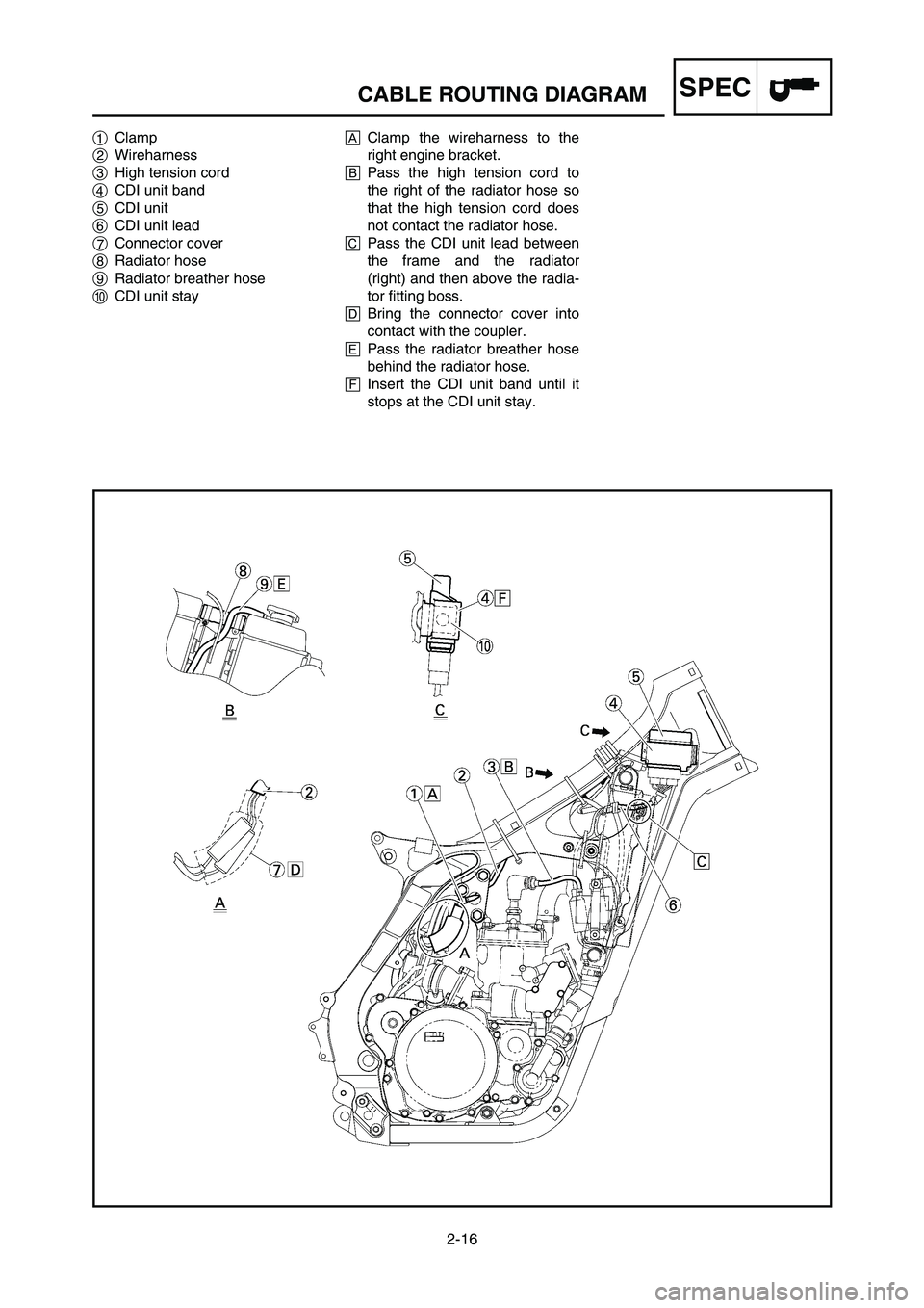
1Clamp
2Wireharness
3High tension cord
4CDI unit band
5CDI unit
6CDI unit lead
7Connector cover
8Radiator hose
9Radiator breather hose
0CDI unit stayAClamp the wireharness to the
right engine bracket.
BPass the high tension cord to
the right of the radiator hose so
that the high tension cord does
not contact the radiator hose.
CPass the CDI unit lead between
the frame and the radiator
(right) and then above the radia-
tor fitting boss.
DBring the connector cover into
contact with the coupler.
EPass the radiator breather hose
behind the radiator hose.
FInsert the CDI unit band until it
stops at the CDI unit stay.
1P8-9-32-2 4/29/06 11:46 AM Page 58
Page 125 of 596
2-16
SCHEMA DE CHEMINEMENT DES CABLES
KABELFÜHRUNGSÜBERSICHTPLAN
DIAGRAMMA DEL PASSAGGIO DEI CAVISPEC
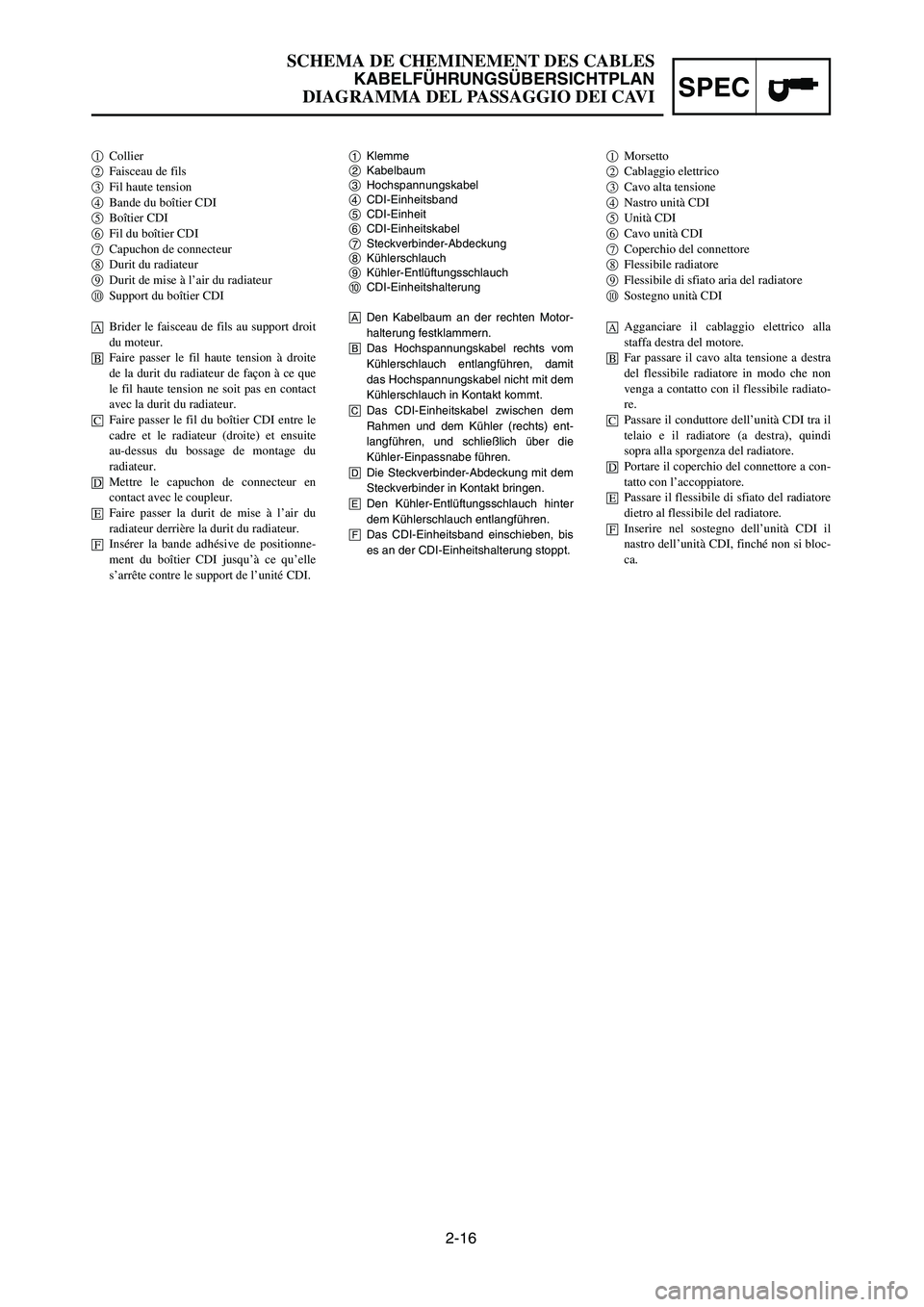
1Klemme
2Kabelbaum
3Hochspannungskabel
4CDI-Einheitsband
5CDI-Einheit
6CDI-Einheitskabel
7Steckverbinder-Abdeckung
8Kühlerschlauch
9Kühler-Entlüftungsschlauch
0CDI-Einheitshalterung
ADen Kabelbaum an der rechten Motor-
halterung festklammern.
BDas Hochspannungskabel rechts vom
Kühlerschlauch entlangführen, damit
das Hochspannungskabel nicht mit dem
Kühlerschlauch in Kontakt kommt.
CDas CDI-Einheitskabel zwischen dem
Rahmen und dem Kühler (rechts) ent-
langführen, und schließlich über die
Kühler-Einpassnabe führen.
DDie Steckverbinder-Abdeckung mit dem
Steckverbinder in Kontakt bringen.
EDen Kühler-Entlüftungsschlauch hinter
dem Kühlerschlauch entlangführen.
FDas CDI-Einheitsband einschieben, bis
es an der CDI-Einheitshalterung stoppt. 1Collier2Faisceau de fils3Fil haute tension4Bande du boîtier CDI 5Boîtier CDI6Fil du boîtier CDI 7Capuchon de connecteur 8Durit du radiateur9Durit de mise à l’air du radiateur0Support du boîtier CDI
ABrider le faisceau de fils au support droit
du moteur.
BFaire passer le fil haute tension à droite
de la durit du radiateur de façon à ce que
le fil haute tension ne soit pas en contact
avec la durit du radiateur.
CFaire passer le fil du boîtier CDI entre le
cadre et le radiateur (droite) et ensuite
au-dessus du bossage de montage du
radiateur.
DMettre le capuchon de connecteur en
contact avec le coupleur.
EFaire passer la durit de mise à l’air du
radiateur derrière la durit du radiateur.
FInsérer la bande adhésive de positionne-
ment du boîtier CDI jusqu’à ce qu’elle
s’arrête contre le support de l’unité CDI.
1Morsetto2Cablaggio elettrico3Cavo alta tensione4Nastro unità CDI5Unità CDI6Cavo unità CDI7Coperchio del connettore8Flessibile radiatore9Flessibile di sfiato aria del radiatore0Sostegno unità CDI
AAgganciare il cablaggio elettrico alla
staffa destra del motore.
BFar passare il cavo alta tensione a destra
del flessibile radiatore in modo che non
venga a contatto con il flessibile radiato-
re.
CPassare il conduttore dell’unità CDI tra il
telaio e il radiatore (a destra), quindi
sopra alla sporgenza del radiatore.
DPortare il coperchio del connettore a con-
tatto con l’accoppiatore.
EPassare il flessibile di sfiato del radiatore
dietro al flessibile del radiatore.
FInserire nel sostegno dell’unità CDI il
nastro dell’unità CDI, finché non si bloc-
ca.
1P8-9-32-2 4/29/06 11:46 AM Page 59
Page 126 of 596
2-17
CABLE ROUTING DIAGRAMSPEC
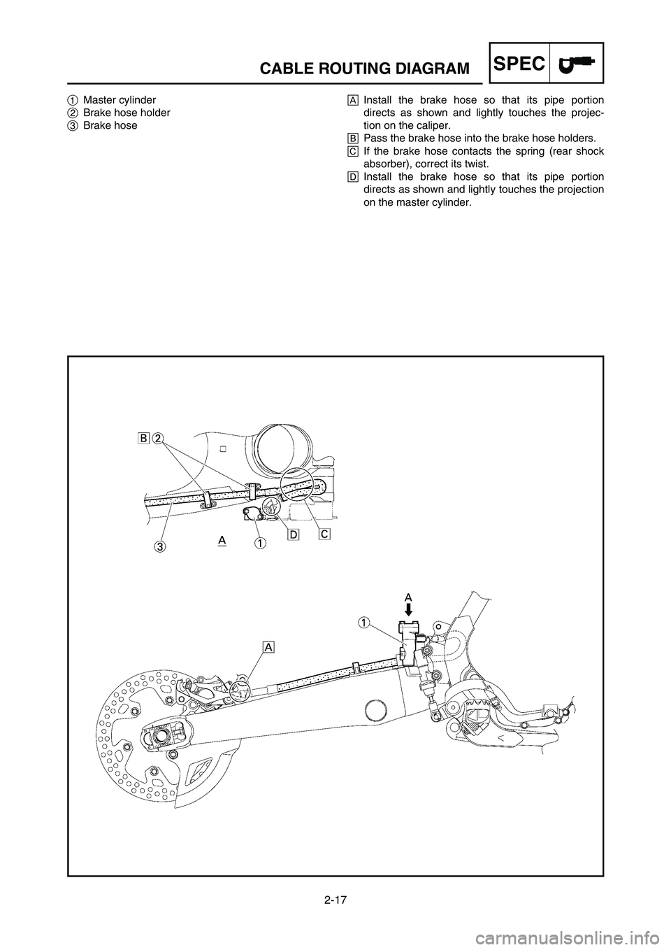
1Master cylinder
2Brake hose holder
3Brake hoseAInstall the brake hose so that its pipe portion
directs as shown and lightly touches the projec-
tion on the caliper.
BPass the brake hose into the brake hose holders.
CIf the brake hose contacts the spring (rear shock
absorber), correct its twist.
DInstall the brake hose so that its pipe portion
directs as shown and lightly touches the projection
on the master cylinder.
1P8-9-32-2 4/29/06 11:46 AM Page 60
Page 127 of 596
2-17
SCHEMA DE CHEMINEMENT DES CABLES
KABELFÜHRUNGSÜBERSICHTPLAN
DIAGRAMMA DEL PASSAGGIO DEI CAVISPEC
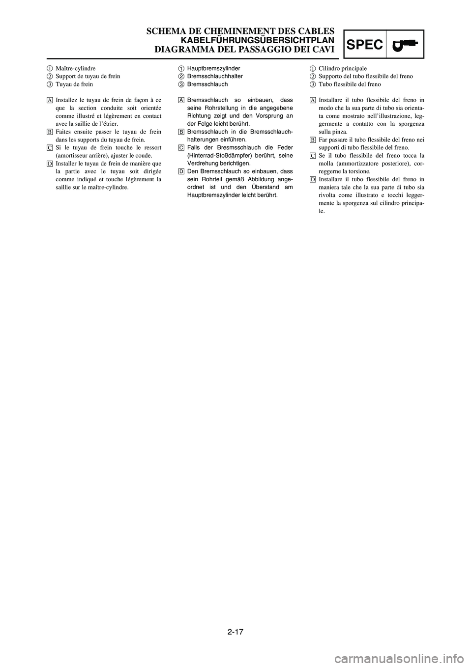
1Hauptbremszylinder
2Bremsschlauchhalter
3Bremsschlauch
ABremsschlauch so einbauen, dass
seine Rohrstellung in die angegebene
Richtung zeigt und den Vorsprung an
der Felge leicht berührt.
BBremsschlauch in die Bremsschlauch-
halterungen einführen.
CFalls der Bresmsschlauch die Feder
(Hinterrad-Stoßdämpfer) berührt, seine
Verdrehung berichtigen.
DDen Bremsschlauch so einbauen, dass
sein Rohrteil gemäß Abbildung ange-
ordnet ist und den Überstand am
Hauptbremszylinder leicht berührt. 1Maître-cylindre2Support de tuyau de frein3Tuyau de frein
åInstallez le tuyau de frein de façon à ce
que la section conduite soit orientée
comme illustré et légèrement en contact
avec la saillie de l’étrier.
∫Faites ensuite passer le tuyau de frein
dans les supports du tuyau de frein.
çSi le tuyau de frein touche le ressort
(amortisseur arrière), ajuster le coude.
∂Installer le tuyau de frein de manière que
la partie avec le tuyau soit dirigée
comme indiqué et touche légèrement la
saillie sur le maître-cylindre.
1Cilindro principale2Supporto del tubo flessibile del freno3Tubo flessibile del freno
åInstallare il tubo flessibile del freno in
modo che la sua parte di tubo sia orienta-
ta come mostrato nell’illustrazione, leg-
germente a contatto con la sporgenza
sulla pinza.
∫Far passare il tubo flessibile del freno nei
supporti di tubo flessibile del freno.
çSe il tubo flessibile del freno tocca la
molla (ammortizzatore posteriore), cor-
reggerne la torsione.
∂Installare il tubo flessibile del freno in
maniera tale che la sua parte di tubo sia
rivolta come illustrato e tocchi legger-
mente la sporgenza sul cilindro principa-
le.
1P8-9-32-2 4/29/06 11:46 AM Page 61
Page 128 of 596
SPEC
2-18
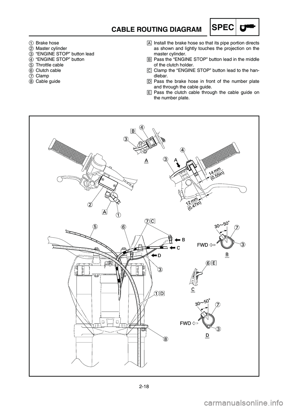
CABLE ROUTING DIAGRAM
1Brake hose
2Master cylinder
3“ENGINE STOP” button lead
4“ENGINE STOP” button
5Throttle cable
6Clutch cable
7Clamp
8Cable guideAInstall the brake hose so that its pipe portion directs
as shown and lightly touches the projection on the
master cylinder.
BPass the “ENGINE STOP” button lead in the middle
of the clutch holder.
CClamp the “ENGINE STOP” button lead to the han-
dlebar.
DPass the brake hose in front of the number plate
and through the cable guide.
EPass the clutch cable through the cable guide on
the number plate.
1P8-9-32-2 4/29/06 11:46 AM Page 62
Page 129 of 596
SPEC
2-18
SCHEMA DE CHEMINEMENT DES CABLES
KABELFÜHRUNGSÜBERSICHTPLAN
DIAGRAMMA DEL PASSAGGIO DEI CAVI
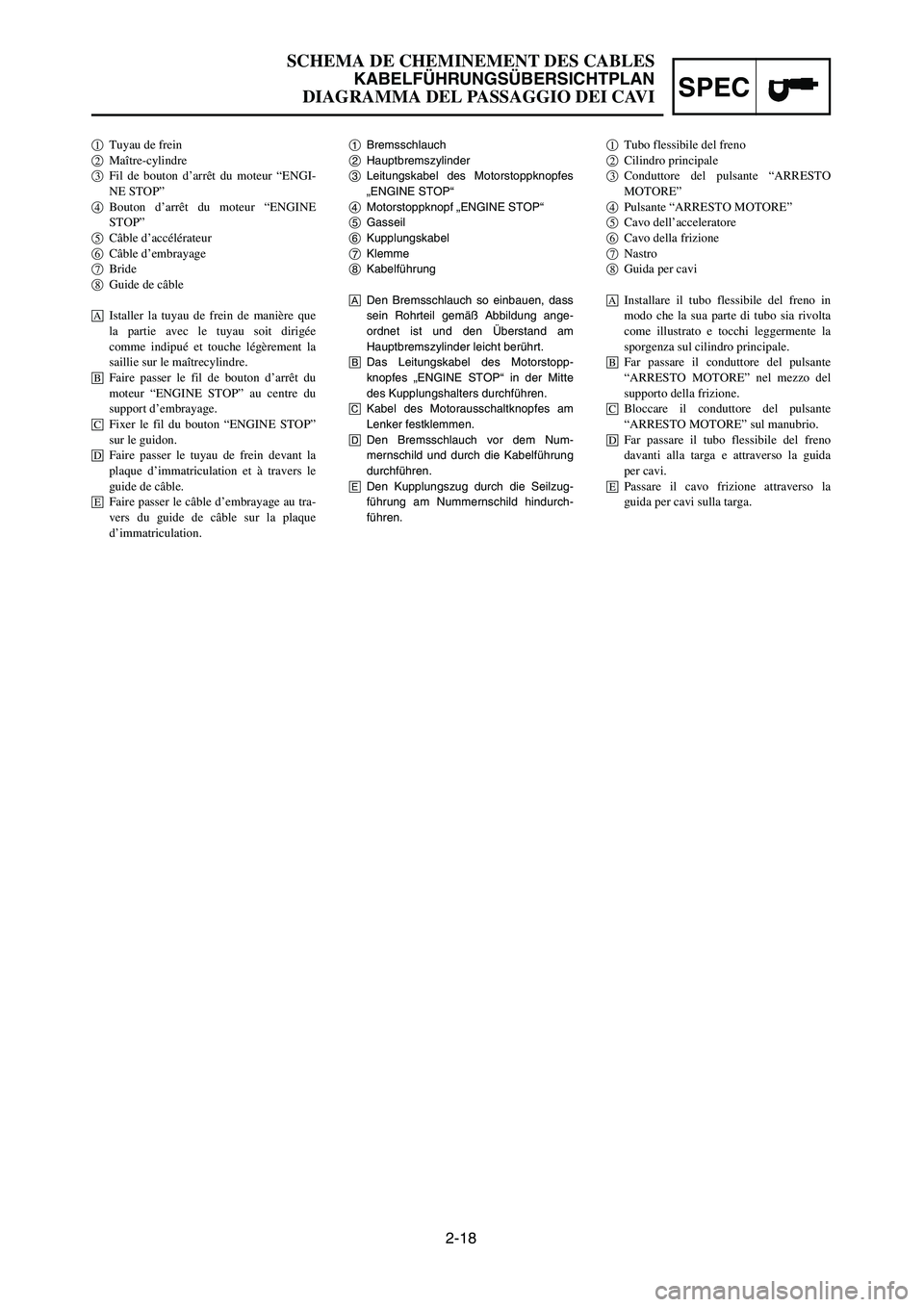
1Bremsschlauch
2Hauptbremszylinder
3Leitungskabel des Motorstoppknopfes
„ENGINE STOP“
4Motorstoppknopf „ENGINE STOP“
5Gasseil
6Kupplungskabel
7Klemme
8Kabelführung
ADen Bremsschlauch so einbauen, dass
sein Rohrteil gemäß Abbildung ange-
ordnet ist und den Überstand am
Hauptbremszylinder leicht berührt.
BDas Leitungskabel des Motorstopp-
knopfes „ENGINE STOP“ in der Mitte
des Kupplungshalters durchführen.
CKabel des Motorausschaltknopfes am
Lenker festklemmen.
DDen Bremsschlauch vor dem Num-
mernschild und durch die Kabelführung
durchführen.
EDen Kupplungszug durch die Seilzug-
führung am Nummernschild hindurch-
führen. 1Tuyau de frein2Maître-cylindre3Fil de bouton d’arrêt du moteur “ENGI-
NE STOP”
4Bouton d’arrêt du moteur “ENGINE
STOP”
5Câble d’accélérateur6Câble d’embrayage7Bride8Guide de câble
åIstaller la tuyau de frein de manière que
la partie avec le tuyau soit dirigée
comme indipué et touche légèrement la
saillie sur le maîtrecylindre.
∫Faire passer le fil de bouton d’arrêt du
moteur “ENGINE STOP” au centre du
support d’embrayage.
çFixer le fil du bouton “ENGINE STOP”
sur le guidon.
∂Faire passer le tuyau de frein devant la
plaque d’immatriculation et à travers le
guide de câble.
´Faire passer le câble d’embrayage au tra-
vers du guide de câble sur la plaque
d’immatriculation.
1Tubo flessibile del freno2Cilindro principale3Conduttore del pulsante “ARRESTO
MOTORE”
4Pulsante “ARRESTO MOTORE”5Cavo dell’acceleratore6Cavo della frizione7Nastro8Guida per cavi
åInstallare il tubo flessibile del freno in
modo che la sua parte di tubo sia rivolta
come illustrato e tocchi leggermente la
sporgenza sul cilindro principale.
∫Far passare il conduttore del pulsante
“ARRESTO MOTORE” nel mezzo del
supporto della frizione.
çBloccare il conduttore del pulsante
“ARRESTO MOTORE” sul manubrio.
∂Far passare il tubo flessibile del freno
davanti alla targa e attraverso la guida
per cavi.
´Passare il cavo frizione attraverso la
guida per cavi sulla targa.
1P8-9-32-2 4/29/06 11:46 AM Page 63
Page 230 of 596
4-6
ENGRADIATOR
EC455000
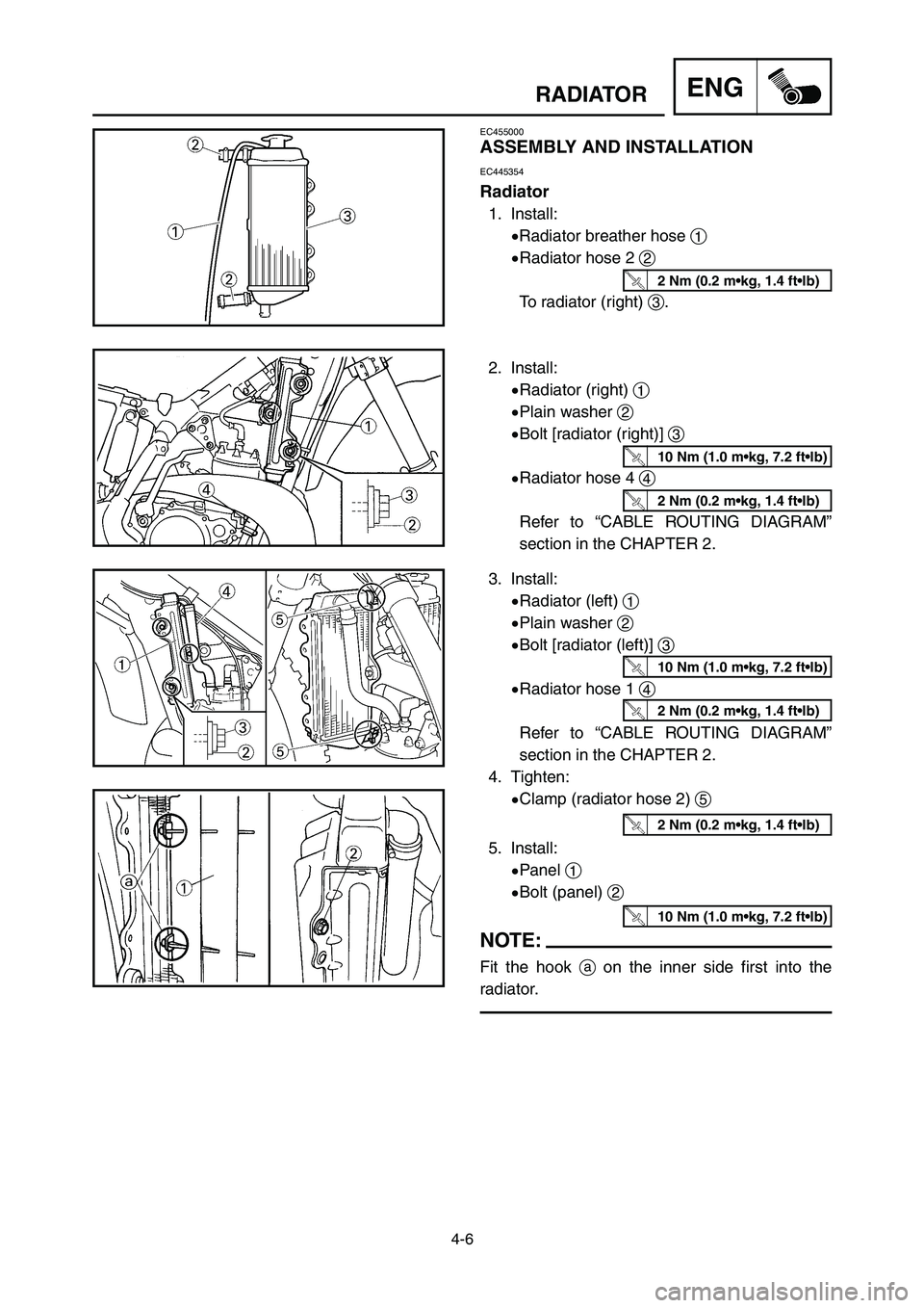
ASSEMBLY AND INSTALLATION
EC445354
Radiator
1. Install:
9Radiator breather hose 1
9Radiator hose 2 2
To radiator (right) 3.
2. Install:
9Radiator (right) 1
9Plain washer 2
9Bolt [radiator (right)] 3
9Radiator hose 4 4
Refer to “CABLE ROUTING DIAGRAM”
section in the CHAPTER 2.
10 Nm (1.0 m•kg, 7.2 ft•lb)
2 Nm (0.2 m•kg, 1.4 ft•lb)
2 Nm (0.2 m•kg, 1.4 ft•lb)
3. Install:
9Radiator (left) 1
9Plain washer 2
9Bolt [radiator (left)] 3
9Radiator hose 1 4
Refer to “CABLE ROUTING DIAGRAM”
section in the CHAPTER 2.
4. Tighten:
9Clamp (radiator hose 2) 5
5. Install:
9Panel 1
9Bolt (panel) 2
NOTE:
Fit the hook aon the inner side first into the
radiator.
10 Nm (1.0 m•kg, 7.2 ft•lb)
2 Nm (0.2 m•kg, 1.4 ft•lb)
2 Nm (0.2 m•kg, 1.4 ft•lb)
10 Nm (1.0 m•kg, 7.2 ft•lb)
1P8-9-32-4a 4/10/06 1:53 PM Page 12
Page 248 of 596
![YAMAHA YZ250LC 2007 User Guide 4-15
ENGCARBURETOR AND REED VALVE
8. Install:
9Air vent hose [
/=580 mm (22.8 in)] 1
9Air vent hose [/=400mm (15.7 in)] 2
9Overflow hose [/=280mm (11.0 in)] 3
9Clamp 4
Refer to “CABLE ROUTING DIAGRA YAMAHA YZ250LC 2007 User Guide 4-15
ENGCARBURETOR AND REED VALVE
8. Install:
9Air vent hose [
/=580 mm (22.8 in)] 1
9Air vent hose [/=400mm (15.7 in)] 2
9Overflow hose [/=280mm (11.0 in)] 3
9Clamp 4
Refer to “CABLE ROUTING DIAGRA](/img/51/53963/w960_53963-247.png)
4-15
ENGCARBURETOR AND REED VALVE
8. Install:
9Air vent hose [
/=580 mm (22.8 in)] 1
9Air vent hose [/=400mm (15.7 in)] 2
9Overflow hose [/=280mm (11.0 in)] 3
9Clamp 4
Refer to “CABLE ROUTING DIAGRAM”
section in the CHAPTER 2.
NOTE:
Install the air vent hoses and overflow hose to
the carburetor with their ends not having the cuts
atoward the carburetor.
9. Install:
9Jet needle 1
9Collar 2
9Spring 3
9Needle holder 4
To throttle valve 5.
NOTE:
Install the spring with its smaller dia. afacing
the collar.
7. Install:
9Float chamber 1
9Plate 2
9Screw (float chamber) 3
1P8-9-32-4a 4/10/06 1:53 PM Page 30
Page 252 of 596
4-17
ENGCARBURETOR AND REED VALVE
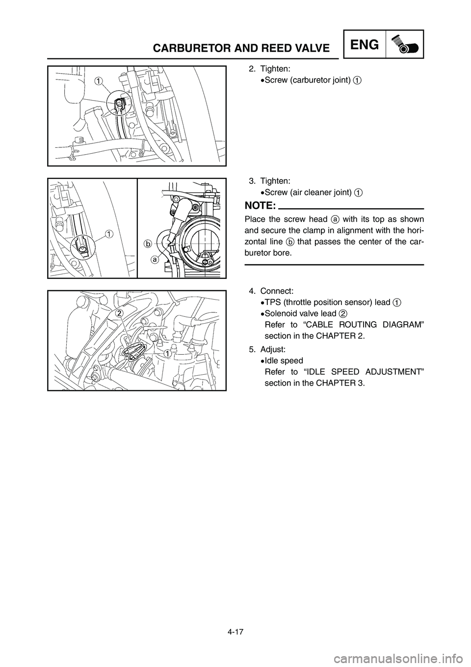
2. Tighten:
9Screw (carburetor joint) 1
3. Tighten:
9Screw (air cleaner joint) 1
NOTE:
Place the screw head awith its top as shown
and secure the clamp in alignment with the hori-
zontal line bthat passes the center of the car-
buretor bore.
4. Connect:
9TPS (throttle position sensor) lead 1
9Solenoid valve lead 2
Refer to “CABLE ROUTING DIAGRAM”
section in the CHAPTER 2.
5. Adjust:
9Idle speed
Refer to “IDLE SPEED ADJUSTMENT”
section in the CHAPTER 3.
1P8-9-32-4a 4/10/06 1:53 PM Page 34
Page 336 of 596
![YAMAHA YZ250LC 2007 User Guide 4-59
CDI MAGNETOENG
7. Connect:
9CDI magneto lead 1
Refer to “CABLE ROUTING DIAGRAM”
section in the CHAPTER 2.
8. Install:
9Gasket [crankcase cover (left)]
9Crankcase cover (left) 1
9Screw [crankc YAMAHA YZ250LC 2007 User Guide 4-59
CDI MAGNETOENG
7. Connect:
9CDI magneto lead 1
Refer to “CABLE ROUTING DIAGRAM”
section in the CHAPTER 2.
8. Install:
9Gasket [crankcase cover (left)]
9Crankcase cover (left) 1
9Screw [crankc](/img/51/53963/w960_53963-335.png)
4-59
CDI MAGNETOENG
7. Connect:
9CDI magneto lead 1
Refer to “CABLE ROUTING DIAGRAM”
section in the CHAPTER 2.
8. Install:
9Gasket [crankcase cover (left)]
9Crankcase cover (left) 1
9Screw [crankcase cover (left)] 2
NOTE:
Tighten the screws in stage, using a crisscross
pattern.
5 Nm (0.5 m•kg, 3.6 ft•lb)
1P8-9-32-4c 5/1/06 10:46 AM Page 20