Valve clearance YAMAHA YZ426F 2001 Owners Manual
[x] Cancel search | Manufacturer: YAMAHA, Model Year: 2001, Model line: YZ426F, Model: YAMAHA YZ426F 2001Pages: 626, PDF Size: 47.57 MB
Page 76 of 626
SPEC
2 - 5
MAINTENANCE SPECIFICATIONS
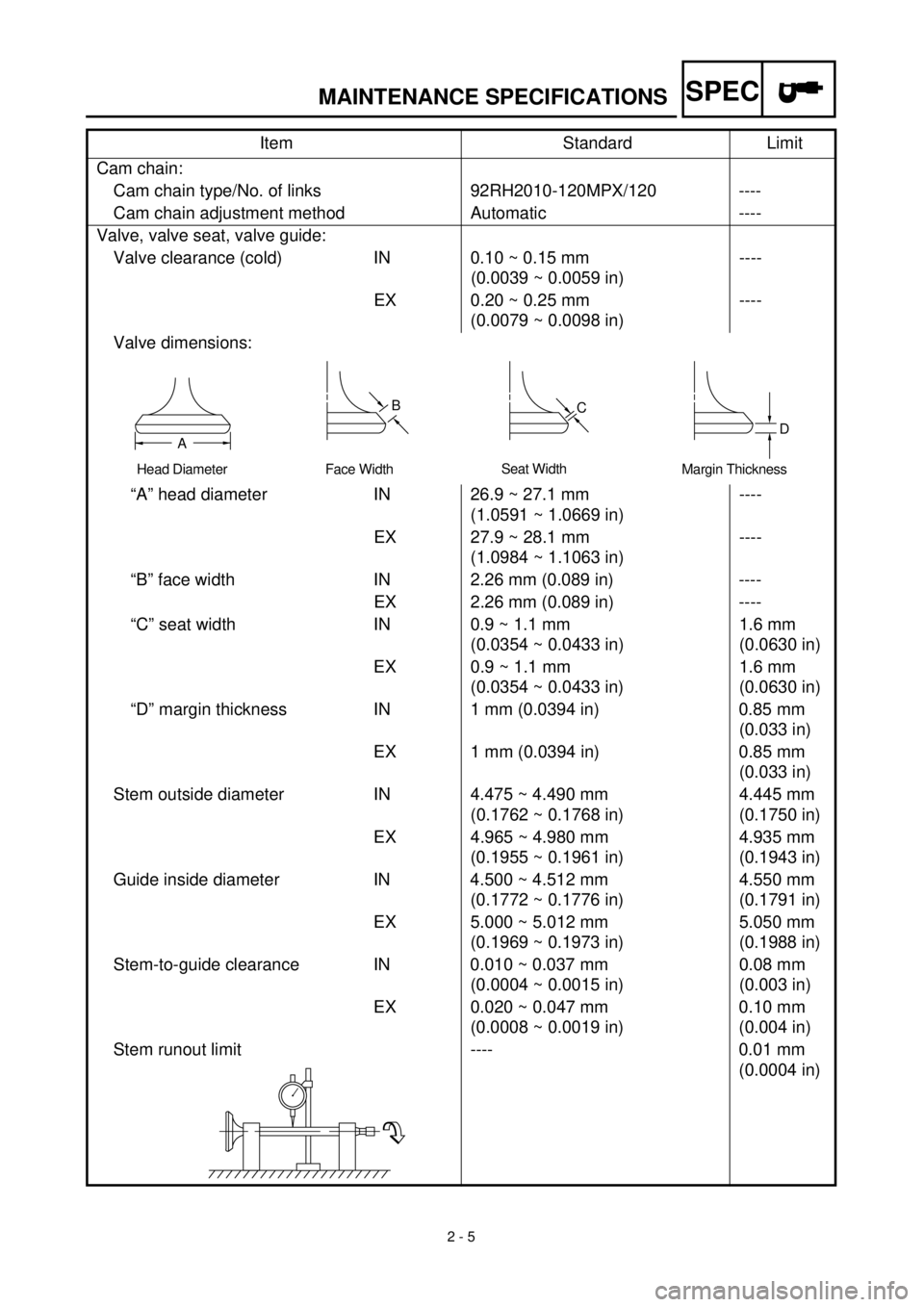
Cam chain:
Cam chain type/No. of links 92RH2010-120MPX/120 ----
Cam chain adjustment method Automatic ----
Valve, valve seat, valve guide:
Valve clearance (cold) IN 0.10 ~ 0.15 mm
(0.0039 ~ 0.0059 in)----
EX 0.20 ~ 0.25 mm
(0.0079 ~ 0.0098 in)----
Valve dimensions:
“A” head diameter IN 26.9 ~ 27.1 mm
(1.0591 ~ 1.0669 in)----
EX 27.9 ~ 28.1 mm
(1.0984 ~ 1.1063 in)----
“B” face width IN 2.26 mm (0.089 in) ----
EX 2.26 mm (0.089 in) ----
“C” seat width IN 0.9 ~ 1.1 mm
(0.0354 ~ 0.0433 in)1.6 mm
(0.0630 in)
EX 0.9 ~ 1.1 mm
(0.0354 ~ 0.0433 in)1.6 mm
(0.0630 in)
“D” margin thickness IN 1 mm (0.0394 in) 0.85 mm
(0.033 in)
EX 1 mm (0.0394 in) 0.85 mm
(0.033 in)
Stem outside diameter IN 4.475 ~ 4.490 mm
(0.1762 ~ 0.1768 in)4.445 mm
(0.1750 in)
EX 4.965 ~ 4.980 mm
(0.1955 ~ 0.1961 in)4.935 mm
(0.1943 in)
Guide inside diameter IN 4.500 ~ 4.512 mm
(0.1772 ~ 0.1776 in)4.550 mm
(0.1791 in)
EX 5.000 ~ 5.012 mm
(0.1969 ~ 0.1973 in)5.050 mm
(0.1988 in)
Stem-to-guide clearance IN 0.010 ~ 0.037 mm
(0.0004 ~ 0.0015 in)0.08 mm
(0.003 in)
EX 0.020 ~ 0.047 mm
(0.0008 ~ 0.0019 in)0.10 mm
(0.004 in)
Stem runout limit ---- 0.01 mm
(0.0004 in) Item Standard Limit
Head Diameter
B
Face WidthC
Seat Width
D
Margin ThicknessA
Page 77 of 626
SPEC
2 - 6
MAINTENANCE SPECIFICATIONS
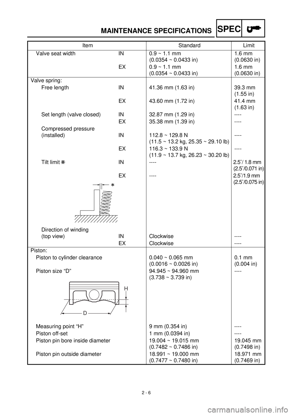
Valve seat width IN 0.9 ~ 1.1 mm
(0.0354 ~ 0.0433 in)1.6 mm
(0.0630 in)
EX 0.9 ~ 1.1 mm
(0.0354 ~ 0.0433 in)1.6 mm
(0.0630 in)
Valve spring:
Free length IN 41.36 mm (1.63 in) 39.3 mm
(1.55 in)
EX 43.60 mm (1.72 in) 41.4 mm
(1.63 in)
Set length (valve closed) IN 32.87 mm (1.29 in) ----
EX 35.38 mm (1.39 in) ----
Compressed pressure
(installed) IN 112.8 ~ 129.8 N
(11.5 ~ 13.2 kg, 25.35 ~ 29.10 lb)----
EX 116.3 ~ 133.9 N
(11.9 ~ 13.7 kg, 26.23 ~ 30.20 lb)----
Tilt limit IN ----2.5˚/ 1.8 mm
(2.5˚/0.071 in)
EX ----2.5˚/1.9 mm
(2.5˚/0.075 in)
Direction of winding
(top view) IN Clockwise ----
EX Clockwise ----
Piston:
Piston to cylinder clearance 0.040 ~ 0.065 mm
(0.0016 ~ 0.0026 in)0.1 mm
(0.004 in)
Piston size “D” 94.945 ~ 94.960 mm
(3.738 ~ 3.739 in)----
Measuring point “H” 9 mm (0.354 in) ----
Piston off-set 1 mm (0.0394 in) ----
Piston pin bore inside diameter 19.004 ~ 19.015 mm
(0.7482 ~ 0.7486 in)19.045 mm
(0.7498 in)
Piston pin outside diameter 18.991 ~ 19.000 mm
(0.7477 ~ 0.7480 in)18.971 mm
(0.7469 in) Item Standard Limit
*
H
D
Page 79 of 626
SPEC
2 - 8
MAINTENANCE SPECIFICATIONS
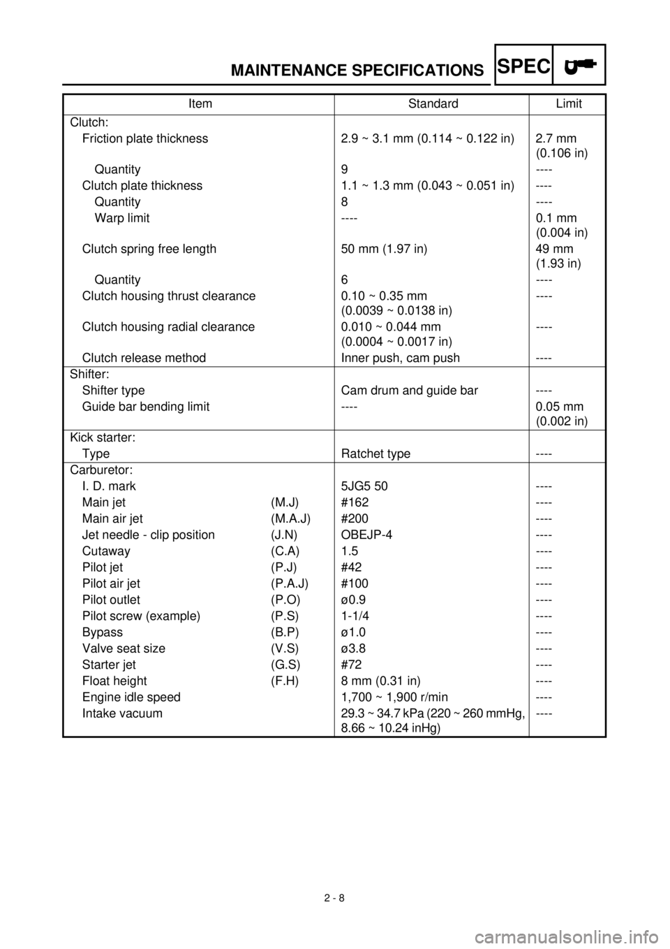
Clutch:
Friction plate thickness 2.9 ~ 3.1 mm (0.114 ~ 0.122 in) 2.7 mm
(0.106 in)
Quantity 9 ----
Clutch plate thickness 1.1 ~ 1.3 mm (0.043 ~ 0.051 in) ----
Quantity 8 ----
Warp limit ---- 0.1 mm
(0.004 in)
Clutch spring free length 50 mm (1.97 in) 49 mm
(1.93 in)
Quantity 6 ----
Clutch housing thrust clearance 0.10 ~ 0.35 mm
(0.0039 ~ 0.0138 in)----
Clutch housing radial clearance 0.010 ~ 0.044 mm
(0.0004 ~ 0.0017 in)----
Clutch release method Inner push, cam push ----
Shifter:
Shifter type Cam drum and guide bar ----
Guide bar bending limit ---- 0.05 mm
(0.002 in)
Kick starter:
Type Ratchet type ----
Carburetor:
I. D. mark 5JG5 50 ----
Main jet (M.J) #162 ----
Main air jet (M.A.J) #200 ----
Jet needle - clip position (J.N) OBEJP-4 ----
Cutaway (C.A) 1.5 ----
Pilot jet (P.J) #42 ----
Pilot air jet (P.A.J) #100 ----
Pilot outlet (P.O) ø0.9 ----
Pilot screw (example) (P.S) 1-1/4 ----
Bypass (B.P) ø1.0 ----
Valve seat size (V.S) ø3.8 ----
Starter jet (G.S) #72 ----
Float height (F.H) 8 mm (0.31 in) ----
Engine idle speed 1,700 ~ 1,900 r/min ----
Intake vacuum29.3 ~ 34.7 kPa (220 ~ 260 mmHg,
8.66 ~ 10.24 inHg)---- Item Standard Limit
Page 80 of 626
SPEC
2 - 9
MAINTENANCE SPECIFICATIONS
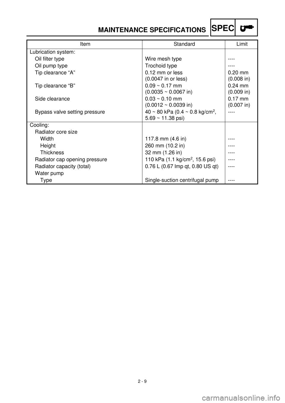
Lubrication system:
Oil filter type Wire mesh type ----
Oil pump type Trochoid type ----
Tip clearance “A” 0.12 mm or less
(0.0047 in or less)0.20 mm
(0.008 in)
Tip clearance “B” 0.09 ~ 0.17 mm
(0.0035 ~ 0.0067 in)0.24 mm
(0.009 in)
Side clearance 0.03 ~ 0.10 mm
(0.0012 ~ 0.0039 in)0.17 mm
(0.007 in)
Bypass valve setting pressure 40 ~ 80 kPa (0.4 ~ 0.8 kg/cm
2
,
5.69 ~ 11.38 psi)----
Cooling:
Radiator core size
Width 117.8 mm (4.6 in) ----
Height 260 mm (10.2 in) ----
Thickness 32 mm (1.26 in) ----
Radiator cap opening pressure 110 kPa (1.1 kg/cm
2
, 15.6 psi) ----
Radiator capacity (total) 0.76 L (0.67 lmp qt, 0.80 US qt) ----
Water pump
Type Single-suction centrifugal pump ----Item Standard Limit
Page 140 of 626
3 - 1
INSP
ADJ
MAINTENANCE INTERVALS
EC300000
REGULAR INSPECTION AND ADJUSTMENTS
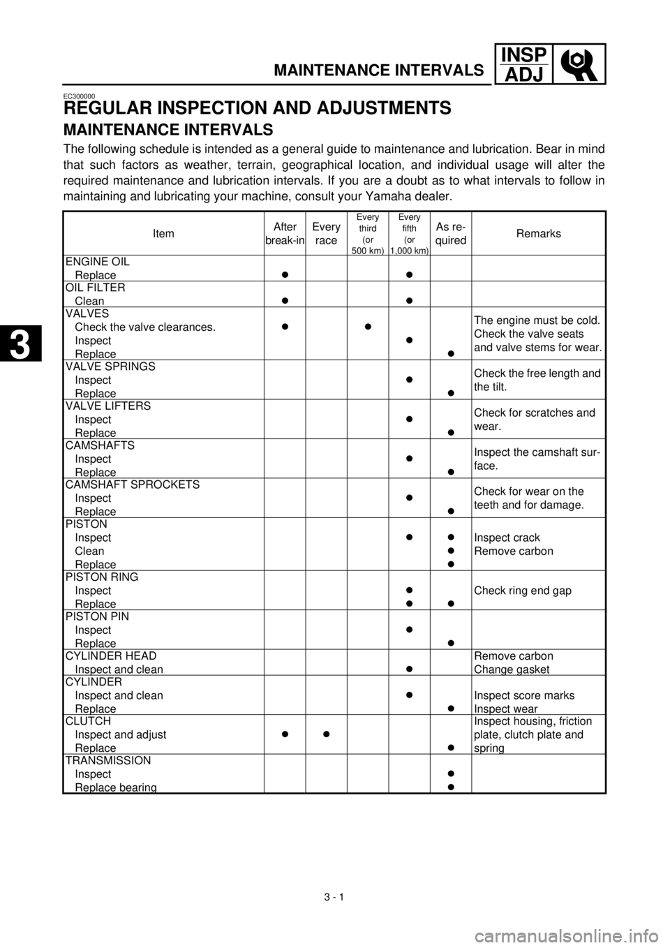
MAINTENANCE INTERVALS
The following schedule is intended as a general guide to maintenance and lubrication. Bear in mind
that such factors as weather, terrain, geographical location, and individual usage will alter the
required maintenance and lubrication intervals. If you are a doubt as to what intervals to follow in
maintaining and lubricating your machine, consult your Yamaha dealer.
ItemAfter
break-inEvery
race
Every
third
(or
500 km)Every
fifth
(or
1,000 km)
As re-
quiredRemarks
ENGINE OIL
Replace
c
c
OIL FILTER
Clean
cc
VALVES
Check the valve clearances.
Inspect
Replace
c
c
c
c
The engine must be cold.
Check the valve seats
and valve stems for wear.
VALVE SPRINGS
Inspect
Replace
c
c
Check the free length and
the tilt.
VALVE LIFTERS
Inspect
Replace
c
c
Check for scratches and
wear.
CAMSHAFTS
Inspect
Replace
c
c
Inspect the camshaft sur-
face.
CAMSHAFT SPROCKETS
Inspect
Replace
c
c
Check for wear on the
teeth and for damage.
PISTON
Inspect
Clean
Replace
c
c
c
c
Inspect crack
Remove carbon
PISTON RING
Inspect
Replace
c
c
c
Check ring end gap
PISTON PIN
Inspect
Replace
c
c
CYLINDER HEAD
Inspect and clean
c
Remove carbon
Change gasket
CYLINDER
Inspect and clean
Replace
c
c
Inspect score marks
Inspect wear
CLUTCH
Inspect and adjust
Replace
c
c
c
Inspect housing, friction
plate, clutch plate and
spring
TRANSMISSION
Inspect
Replace bearing
c
c
3
Page 178 of 626
3 - 18
INSP
ADJIDLE SPEED ADJUSTMENT/
VALVE CLEARANCE ADJUSTMENT
EC35M021
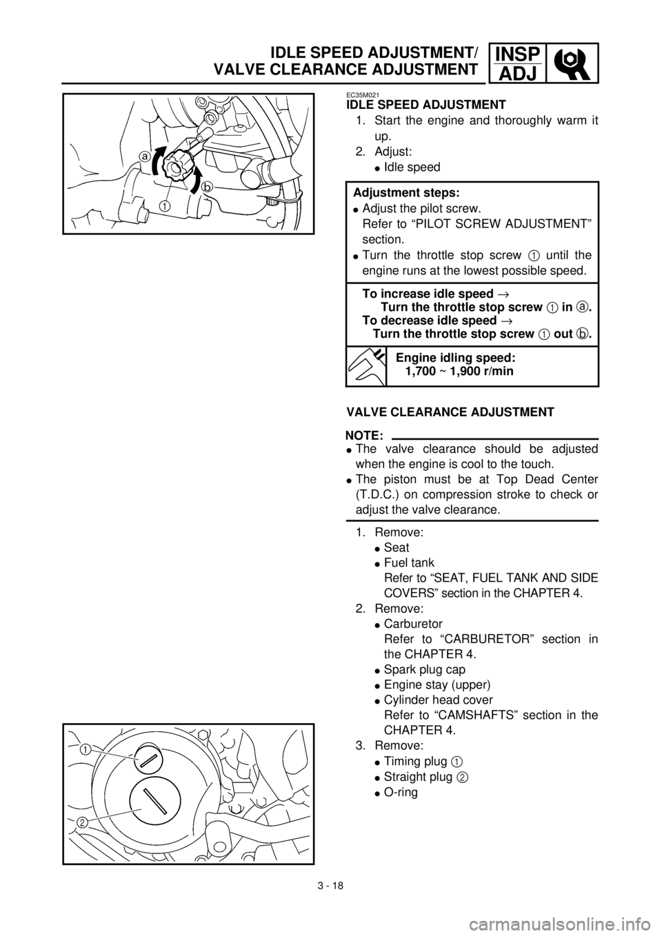
IDLE SPEED ADJUSTMENT
1. Start the engine and thoroughly warm it
up.
2. Adjust:
lIdle speed
Adjustment steps:
lAdjust the pilot screw.
Refer to “PILOT SCREW ADJUSTMENT”
section.
lTurn the throttle stop screw 1 until the
engine runs at the lowest possible speed.
To increase idle speed ®
Turn the throttle stop screw 1 in a.
To decrease idle speed ®
Turn the throttle stop screw 1 out b.
Engine idling speed:
1,700 ~ 1,900 r/min
VALVE CLEARANCE ADJUSTMENT
NOTE:
lThe valve clearance should be adjusted
when the engine is cool to the touch.
lThe piston must be at Top Dead Center
(T.D.C.) on compression stroke to check or
adjust the valve clearance.
1. Remove:
lSeat
lFuel tank
Refer to “SEAT, FUEL TANK AND SIDE
COVERS” section in the CHAPTER 4.
2. Remove:
lCarburetor
Refer to “CARBURETOR” section in
the CHAPTER 4.
lSpark plug cap
lEngine stay (upper)
lCylinder head cover
Refer to “CAMSHAFTS” section in the
CHAPTER 4.
3. Remove:
lTiming plug 1
lStraight plug 2
lO-ring
Page 180 of 626
3 - 19
INSP
ADJ
VALVE CLEARANCE ADJUSTMENT
4. Check:
lValve clearance
Out of specification ® Adjust.
Valve clearance (cold):
Intake valve:
0.10 ~ 0.15 mm (0.0039 ~ 0.0059 in)
Exhaust valve:
0.20 ~ 0.25 mm (0.0079 ~ 0.0098 in)
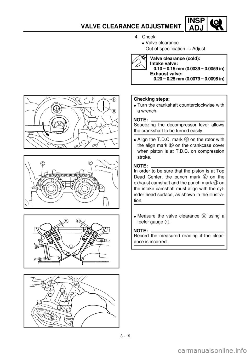
Checking steps:
lTurn the crankshaft counterclockwise with
a wrench.
NOTE:
Squeezing the decompressor lever allows
the crankshaft to be turned easily.
lAlign the T.D.C. mark a on the rotor with
the align mark b on the crankcase cover
when piston is at T.D.C. on compression
stroke.
NOTE:
In order to be sure that the piston is at Top
Dead Center, the punch mark c on the
exhaust camshaft and the punch mark d on
the intake camshaft must align with the cyl-
inder head surface, as shown in the illustra-
tion.
lMeasure the valve clearance e using a
feeler gauge 1.
NOTE:
Record the measured reading if the clear-
ance is incorrect.
Page 182 of 626

3 - 20
INSP
ADJ
VALVE CLEARANCE ADJUSTMENT
5. Adjust:
lValve clearance
Adjustment steps:
lLoosen the timing chain tensioner cap
bolt.
lRemove the timing chain tensioner and
camshaft caps.
NOTE:
Remove the camshaft cap bolts in a criss-
cross pattern from the outside working
inwards.
lRemove the camshaft (intake 1 and
exhaust 2).
NOTE:
Attach a wire 3 to the timing chain to pre-
vent it from falling into the crankcase.
lRemove the decompression guide 4,
cable 5, bolt 6 and decompression shaft
7.
lRemove the valve lifters 8 and the pads
9.
NOTE:
lPlace a rag in the timing chain space to
prevent pads from falling into the crank-
case.
lIdentity each valve lifter and pad position
very carefully so that they can be rein-
stalled in their original place.
lSelect the proper pad using the pad
selecting table.
Pad rangePad Availability:
25 increments
No. 120
~
No. 2401.20 mm
~
2.40 mmPads are available in
0.05 mm increments
NOTE:
The thickness a of each pad is indicated in
hundreths of millimeters on the pad upper
surface.
Page 184 of 626
3 - 21
INSP
ADJ
VALVE CLEARANCE ADJUSTMENT
l
Round off the last digit of the installed pad
number to the nearest increment.
Last digit of pad
numberRounded value
0 or 2 0
5(NOT ROUNDED
OFF)
810
EXAMPLE:
Installed pad number = 148
Rounded off value = 150
NOTE:
Pads can only be selected in 0.05 mm incre-
ments.
l
Locate the rounded-off value and the
measured valve clearance in the chart
“PAD SELECTION TABLE”. The field
where these two coordinates intersect
shows the new pad number to use.
NOTE:
Use the new pad number only as a guide
when verifying the valve clearance adjust-
ment.
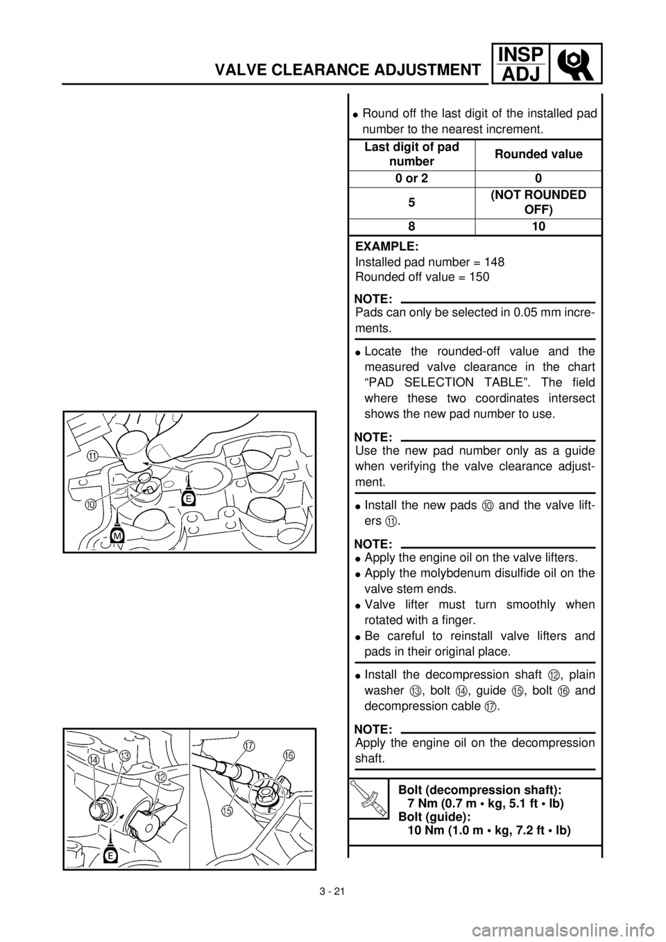
l
Install the new pads
0
and the valve lift-
ers
A
.
NOTE:
l
Apply the engine oil on the valve lifters.
l
Apply the molybdenum disulfide oil on the
valve stem ends.
l
Valve lifter must turn smoothly when
rotated with a finger.
l
Be careful to reinstall valve lifters and
pads in their original place.
l
Install the decompression shaft
B
, plain
washer
C
, bolt
D
, guide
E
, bolt
F
and
decompression cable
G
.
NOTE:
Apply the engine oil on the decompression
shaft.
T R..
Bolt (decompression shaft):
7 Nm (0.7 m • kg, 5.1 ft • lb)
Bolt (guide):
10 Nm (1.0 m • kg, 7.2 ft • lb)
Page 186 of 626
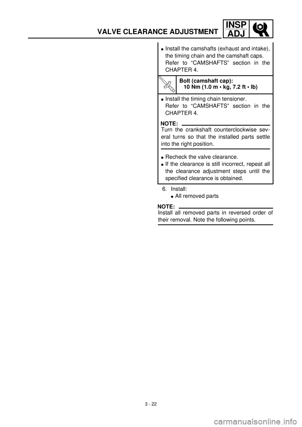
3 - 22
INSP
ADJ
VALVE CLEARANCE ADJUSTMENT
6. Install:
l
All removed parts
NOTE:
Install all removed parts in reversed order of
their removal. Note the following points.
l
Install the camshafts (exhaust and intake),
the timing chain and the camshaft caps.
Refer to “CAMSHAFTS” section in the
CHAPTER 4.
T R..
Bolt (camshaft cap):
10 Nm (1.0 m • kg, 7.2 ft • lb)
l
Install the timing chain tensioner.
Refer to “CAMSHAFTS” section in the
CHAPTER 4.
NOTE:
Turn the crankshaft counterclockwise sev-
eral turns so that the installed parts settle
into the right position.
l
Recheck the valve clearance.
l
If the clearance is still incorrect, repeat all
the clearance adjustment steps until the
specified clearance is obtained.