oil YAMAHA YZ426F 2002 Owner's Manual
[x] Cancel search | Manufacturer: YAMAHA, Model Year: 2002, Model line: YZ426F, Model: YAMAHA YZ426F 2002Pages: 633, PDF Size: 36.22 MB
Page 128 of 633

2 - 19
SPEC
LUBRICATION DIAGRAMS
LUBRICATION DIAGRAMS
1
Oil delivery pipe
2
Intake camshaft
3
Exhaust camshaft
4
Oil cleaner element
5
Oil pump
6
Main axle
7
Drive axle
Page 130 of 633

2 - 20
SPEC
LUBRICATION DIAGRAMS
1
Camshaft
2
Connecting rod
3
Oil cleaner element
4
Crankshaft
5
Main axle
6
Drive axle
7
Oil delivery pipe
Page 132 of 633

2 - 21
SPEC
CABLE ROUTING DIAGRAM
EC240000
CABLE ROUTING DIAGRAM
1
Hose guide
2
Brake hose
3
Fuel tank breather hose
4
Oil tank breather hose
5
Clamp
6
Sub wire harness
7
TPS (throttle position
sensor) lead
8
Neutral switch lead
9
Oil hose
0
Hose holder
A
CDI magneto lead
B
Clutch cable
C
Cylinder head breather hose
D
Carburetor breather hose
E
Overflow hose
Å
Pass the clutch cable through
the cable guide.
ı
Pass the fuel tank breather hose
between the handlebar and ten-
sion bar, then insert its end into
the hole of the number plate.
Ç
Pass the decompression cable
under the oil tank breather pipe.
Î
Fasten the CDI magneto lead
and neutral switch lead to the
frame with a plastic locking tie
and cut off the tie end.
‰
Fasten the sub wire harness to
the frame at the white tape for
the sub wire harness with a
plastic locking tie and cut off the
tie end.
Ï
Pass the cylinder head breather
hose along the right side of the
oil tank breather hose.
Ì
Fasten the sub wire harness to
the frame with a plastic locking
tie ends at the lower left of the
frame and cut off the tie end. For
fastening, pass the plastic lock-
ing tie through the upper holes
in the engine brackets.
Ó
Pass the sub wire harness
between the engine brackets.
Page 134 of 633

2 - 22
SPEC
CABLE ROUTING DIAGRAM
È
Fasten the TPS lead (in the
sub wire harness) under the
frame so that it does not con-
tact the carburetor.
Ô
Make sure that the TPS lead
coupler does not go outside the
chassis.
Fasten the TPS lead under the
coupler to the frame with a
plastic locking tie.
Ò
Pass the carburetor breather
hose and overflow hose
between the connecting rod
and cross tube (frame).
˜Fasten the neutral switch lead
and oil hose together with a
plastic locking tie and cut off
the tie end.ˆFasten the cylinder head
breather hose with the hose
holder.
ØFasten the neutral switch lead
to the frame with a plastic band
ends toward the rear of the
frame.
∏Fasten the cylinder head
breather hose with the hose
holder.
ŒPass the clutch cable through
the cable guide.
ÂFasten the neutral switch lead
and CDI magneto lead together
with a plastic band.
ÍPass the clutch cable on the
inside the cylinder head
breather hose.ÊPass the cylinder head
breather hose along the inner
side of the radiator pipe.
ËPass the radiator breather
hose from the right side of the
frame to the left side, over radi-
ator pipe 1, along the inner side
of radiator hose 4 and the radi-
ator, and between the lower
engine bracket, crankcase, oil
hose and the frame.
◊Pass the clutch cable between
the frame and radiator and
over the lower boss on the radi-
ator.
Page 136 of 633
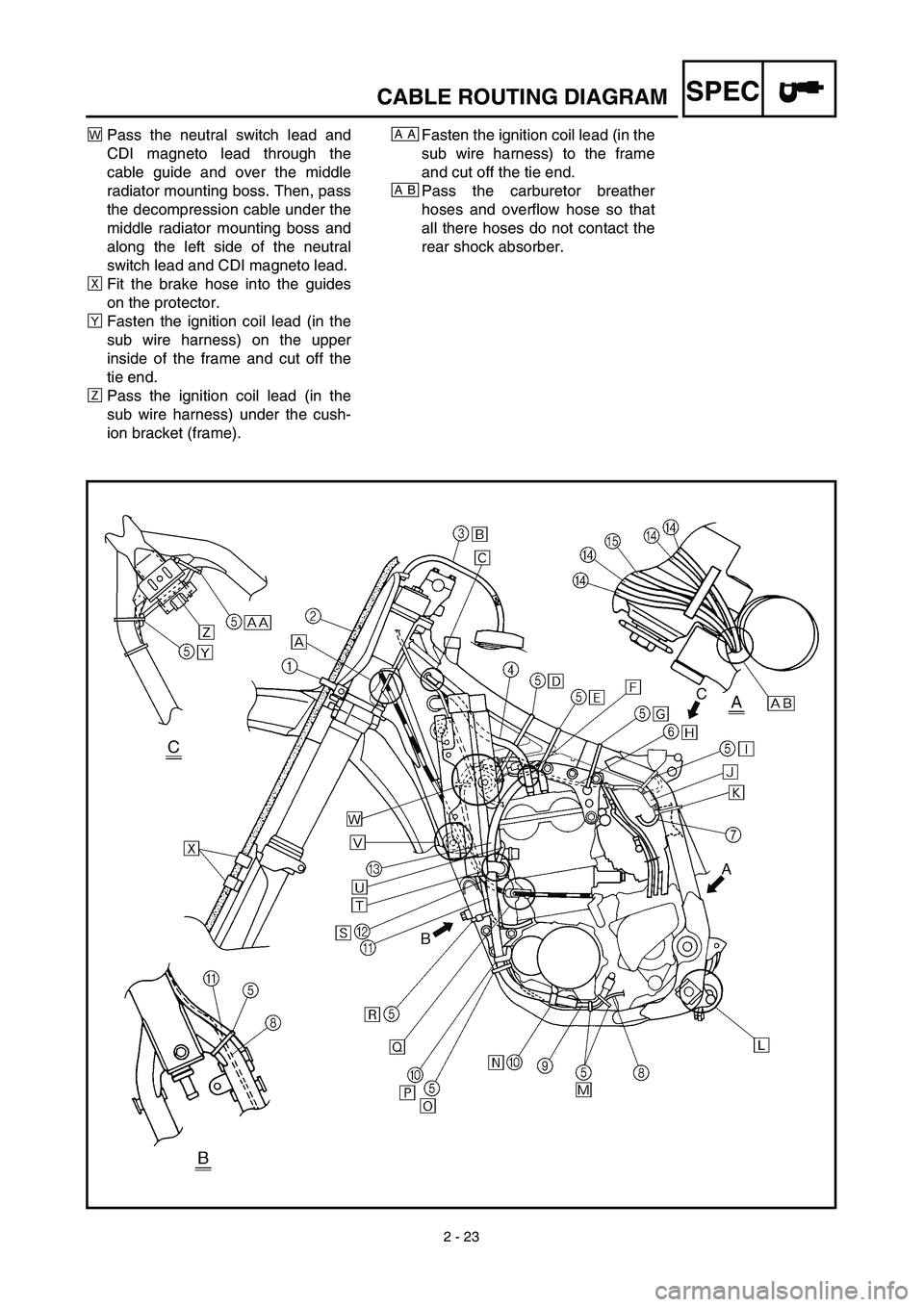
2 - 23
SPEC
„Pass the neutral switch lead and
CDI magneto lead through the
cable guide and over the middle
radiator mounting boss. Then, pass
the decompression cable under the
middle radiator mounting boss and
along the left side of the neutral
switch lead and CDI magneto lead.
ÙFit the brake hose into the guides
on the protector.
ÁFasten the ignition coil lead (in the
sub wire harness) on the upper
inside of the frame and cut off the
tie end.
ÛPass the ignition coil lead (in the
sub wire harness) under the cush-
ion bracket (frame).Fasten the ignition coil lead (in the
sub wire harness) to the frame
and cut off the tie end.
Pass the carburetor breather
hoses and overflow hose so that
all there hoses do not contact the
rear shock absorber.AA
AB
CABLE ROUTING DIAGRAM
Page 138 of 633
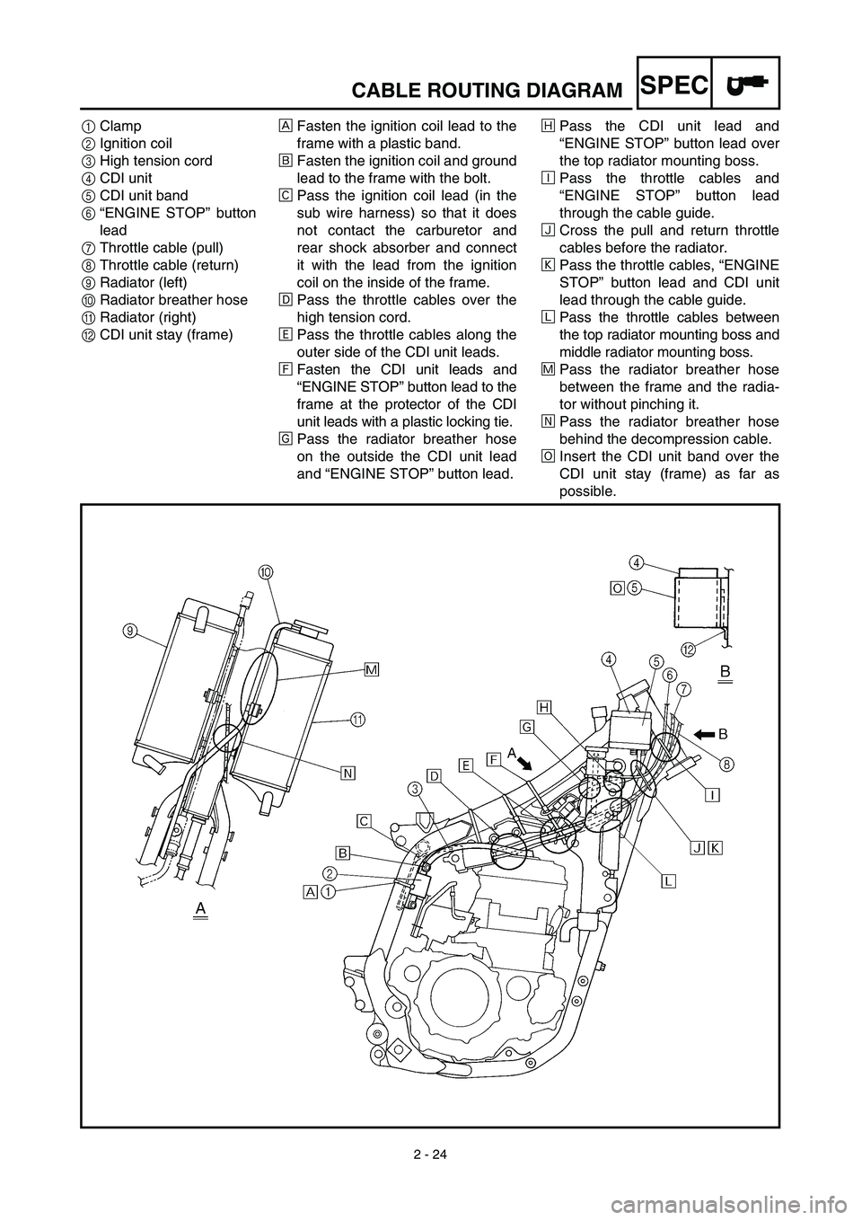
2 - 24
SPECCABLE ROUTING DIAGRAM
1Clamp
2Ignition coil
3High tension cord
4CDI unit
5CDI unit band
6“ENGINE STOP” button
lead
7Throttle cable (pull)
8Throttle cable (return)
9Radiator (left)
0Radiator breather hose
ARadiator (right)
BCDI unit stay (frame)ÅFasten the ignition coil lead to the
frame with a plastic band.
ıFasten the ignition coil and ground
lead to the frame with the bolt.
ÇPass the ignition coil lead (in the
sub wire harness) so that it does
not contact the carburetor and
rear shock absorber and connect
it with the lead from the ignition
coil on the inside of the frame.
ÎPass the throttle cables over the
high tension cord.
‰Pass the throttle cables along the
outer side of the CDI unit leads.
ÏFasten the CDI unit leads and
“ENGINE STOP” button lead to the
frame at the protector of the CDI
unit leads with a plastic locking tie.
ÌPass the radiator breather hose
on the outside the CDI unit lead
and “ENGINE STOP” button lead.ÓPass the CDI unit lead and
“ENGINE STOP” button lead over
the top radiator mounting boss.
ÈPass the throttle cables and
“ENGINE STOP” button lead
through the cable guide.
ÔCross the pull and return throttle
cables before the radiator.
Pass the throttle cables, “ENGINE
STOP” button lead and CDI unit
lead through the cable guide.
ÒPass the throttle cables between
the top radiator mounting boss and
middle radiator mounting boss.
˜Pass the radiator breather hose
between the frame and the radia-
tor without pinching it.
ˆPass the radiator breather hose
behind the decompression cable.
ØInsert the CDI unit band over the
CDI unit stay (frame) as far as
possible.
Page 142 of 633

3 - 1
INSP
ADJ
MAINTENANCE INTERVALS
EC300000
REGULAR INSPECTION AND ADJUSTMENTS
MAINTENANCE INTERVALS
The following schedule is intended as a general guide to maintenance and lubrication. Bear in mind
that such factors as weather, terrain, geographical location, and individual usage will alter the
required maintenance and lubrication intervals. If you are a doubt as to what intervals to follow in
maintaining and lubricating your machine, consult your Yamaha dealer.
ItemAfter
break-inEvery
race
Every
third
(or
500 km)Every
fifth
(or
1,000 km)
As re-
quiredRemarks
ENGINE OIL
Replace
●
●
OIL FILTER
Clean
●●
VALVES
Check the valve clearances.
Inspect
Replace
●
●
●
●
The engine must be cold.
Check the valve seats
and valve stems for wear.
VALVE SPRINGS
Inspect
Replace
●
●
Check the free length and
the tilt.
VALVE LIFTERS
Inspect
Replace
●
●
Check for scratches and
wear.
CAMSHAFTS
Inspect
Replace
●
●
Inspect the camshaft sur-
face.
CAMSHAFT SPROCKETS
Inspect
Replace
●
●
Check for wear on the
teeth and for damage.
PISTON
Inspect
Clean
Replace
●
●
●
●
Inspect crack
Remove carbon
PISTON RING
Inspect
Replace
●
●
●
Check ring end gap
PISTON PIN
Inspect
Replace
●
●
CYLINDER HEAD
Inspect and clean
●
Remove carbon
Change gasket
CYLINDER
Inspect and clean
Replace
●
●
Inspect score marks
Inspect wear
CLUTCH
Inspect and adjust
Replace
●
●
●
Inspect housing, friction
plate, clutch plate and
spring
TRANSMISSION
Inspect
Replace bearing
●
●
Page 143 of 633

3 - 2
INSP
ADJ
MAINTENANCE INTERVALS
SHIFT FORK, SHIFT CAM, GUIDE BAR
Inspect
●
Inspect wear
ROTOR NUT
Retighten
●
●
MUFFLER
Inspect and retighten
Clean
Replace
●
●
●
●
* Whichever comes first
CRANK
Inspect and clean
●
●
CARBURETOR
Inspect, adjust and clean
●
●
When using a high-pres-
sure washer, make sure
that water does not enter
the accelerator pump.
SPARK PLUG
Inspect and clean
Replace
●
●
●
DRIVE CHAIN
Lubricate, slack, alignment
Replace
●
●
●
Use chain lube
Chain slack: 40 ~ 50 mm
(1.6 ~ 2.0 in)
COOLING SYSTEM
Check coolant level and leakage
Check radiator cap operation
Replace coolant
Inspect hoses
●
●
●
●
●
Every two years
OUTSIDE NUTS AND BOLTS
Retighten
●
●
Refer to “STARTING
AND BREAK-IN” section
in the CHAPTER 1.
AIR FILTER
Clean and lubricate
Replace
●
●
●
Use foam air-filter oil
OIL STRAINER (frame)
Clean
●
FRAME
Clean and inspect
●
●
FUEL TANK, COCK
Clean and inspect
●
●
BRAKES
Adjust lever position and pedal height
Lubricate pivot point
Check brake disc surface
Check fluid level and leakage
Retighten brake disc bolts, caliper
bolts, master cylinder bolts and union
bolts
Replace pads
Replace brake fluid
●
●
●
●
●
●
●
●
●
●
●
●
Every one year
FRONT FORKS
Inspect and adjust
Replace oil
Replace oil seal
●
●
●
●
●
Suspension oil “01” ItemAfter
break-inEvery
race
Every
third
(or
500 km)Every
fifth
(or
1,000 km)
As re-
quiredRemarks
1
2
3
Page 144 of 633

3 - 3
INSP
ADJ
MAINTENANCE INTERVALS
FRONT FORK OIL SEAL AND DUST
SEAL
Clean and lube
●
●
Lithium base grease
REAR SHOCK ABSORBER
Inspect and adjust
Lube
Retighten
●
●
●
●
●
(After
rain ride)
●
Molybdenum disulfide
grease
CHAIN GUARD AND ROLLERS
Inspect
●
●
SWINGARM
Inspect, lube and retighten
● ● Molybdenum disulfide
grease
RELAY ARM, CONNECTING ROD
Inspect, lube and retighten
● ● Molybdenum disulfide
grease
STEERING HEAD
Inspect free play and retighten
Clean and lube
Replace bearing
● ●
●
● Lithium base grease
TIRE, WHEELS
Inspect air pressure, wheel run-out,
tire wear and spoke looseness
Retighten sprocket bolt
Inspect bearings
Replace bearings
Lubricate
●
●
●
●
●
●
●
Lithium base grease
THROTTLE, CONTROL CABLE
Check routing and connection
Lubricate
●
●
●
● Yamaha cable lube or
SAE 10W-30 motor oil ItemAfter
break-inEvery
race
Every
third
(or
500 km)Every
fifth
(or
1,000 km)As re-
quiredRemarks
Page 147 of 633

INSP
ADJ
PROGRAMME D’ENTRETIEN
FOURCHE AVANT
Contrôler et régler
Changer l’huile
Changer la bague d’étanchéité
●
●●
●
●
Huile de suspension “01”
BAGUE D’ETANCHEITE ET JOINT
ANTIPOUSSIERE DE FOURCHE
AVANT
Nettoyer et lubrifier
●●
Graisse à base de lithium
AMORTISSEUR ARRIERE
Contrôler et régler
Lubrifier
Resserrer
●
●●
●●
(Aprèscon-
duite sous
la pluie)
●
Graisse au bisulfure de
molybdène
GUIDE-CHAINE ET ROULEAU
Contrôler
●●
BRAS OSCILLANT
Contrôler, lubrifier et resserrer
●●
Graisse au bisulfure de
molybdène
BRAS RELAIS, BIELLE
Contrôler, lubrifier et resserrer
●●
Graisse au bisulfure de
molybdène
TETE DE FOURCHE
Contrôler le jeu
Nettoyer et lubrifier
Changer le roulement
●●
●
●
Graisse à base de lithium
PNEU, ROUES
Contrôler la pression de gonflage, le voile
de roue et l’usure des pneus et la tension
des rayons
Resserrer les boulons de la roue dentée
Contrôler les roulements
Changer les roulements
Graisser
●
●●
●
●
●●
Graisse à base de lithium
ACCELERATEUR, CABLES DE COM-
MANDE
Contrôler le cheminement et le branche-
ment
Graisser
●
●●
●
Yamaha lube pour câble ou
Huile moteur SAE 10W-30 PartieAprès
rodageChaque
course
Chaque
3ème (ou
500 km)Chaque
5ème (ou
1.000 km)
Si
néces-
saireRemarques
3 - 3