stop start YAMAHA YZ450F 2005 Notices Demploi (in French)
[x] Cancel search | Manufacturer: YAMAHA, Model Year: 2005, Model line: YZ450F, Model: YAMAHA YZ450F 2005Pages: 646, PDF Size: 16.06 MB
Page 83 of 646

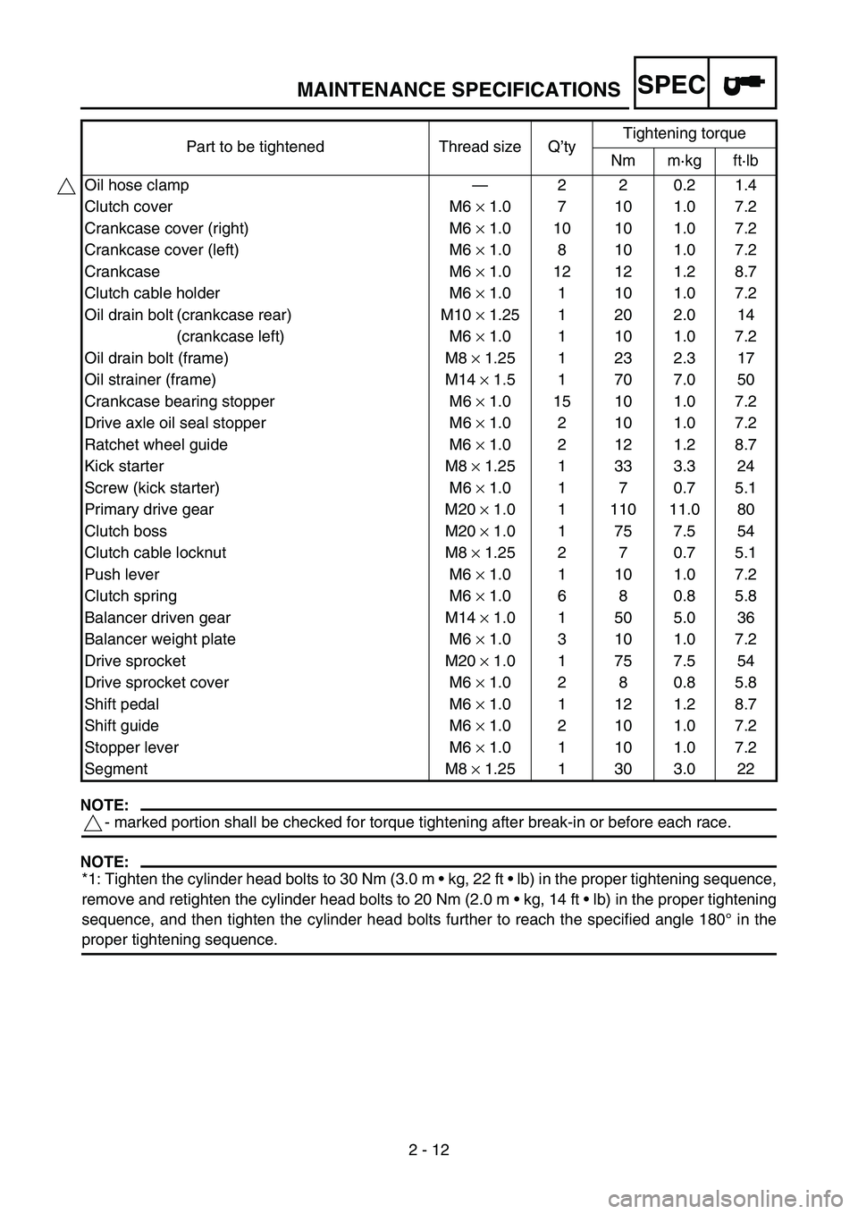
SPEC
2 - 12
NOTE:
- marked portion shall be checked for torque tightening after break-in or before each race.
NOTE:
*1: Tighten the cylinder head bolts to 30 Nm (3.0 m kg, 22 ft lb) in the proper tightening sequence,
remove and retighten the cylinder head bolts to 20 Nm (2.0 m kg, 14 ft lb) in the proper tightening
sequence, and then tighten the cylinder head bolts further to reach the specified angle 180° in the
proper tightening sequence.Oil hose clamp—220.21.4
Clutch cover M6 × 1.0 7 10 1.0 7.2
Crankcase cover (right) M6 × 1.0 10 10 1.0 7.2
Crankcase cover (left) M6 × 1.0 8 10 1.0 7.2
Crankcase M6 × 1.0 12 12 1.2 8.7
Clutch cable holder M6 × 1.0 1 10 1.0 7.2
Oil drain bolt (crankcase rear) M10 × 1.25 1 20 2.0 14
(crankcase left) M6 × 1.0 1 10 1.0 7.2
Oil drain bolt (frame) M8 × 1.25 1 23 2.3 17
Oil strainer (frame) M14 × 1.5 1 70 7.0 50
Crankcase bearing stopper M6 × 1.0 15 10 1.0 7.2
Drive axle oil seal stopper M6 × 1.0 2 10 1.0 7.2
Ratchet wheel guide M6 × 1.0 2 12 1.2 8.7
Kick starter M8 × 1.25 1 33 3.3 24
Screw (kick starter) M6 × 1.0 1 7 0.7 5.1
Primary drive gear M20 × 1.0 1 110 11.0 80
Clutch boss M20 × 1.0 1 75 7.5 54
Clutch cable locknut M8 × 1.25 2 7 0.7 5.1
Push lever M6 × 1.0 1 10 1.0 7.2
Clutch spring M6 × 1.0 6 8 0.8 5.8
Balancer driven gear M14 × 1.0 1 50 5.0 36
Balancer weight plate M6 × 1.0 3 10 1.0 7.2
Drive sprocket M20 × 1.0 1 75 7.5 54
Drive sprocket cover M6 × 1.0 2 8 0.8 5.8
Shift pedal M6 × 1.0 1 12 1.2 8.7
Shift guide M6 × 1.0 2 10 1.0 7.2
Stopper lever M6 × 1.0 1 10 1.0 7.2
Segment M8 × 1.25 1 30 3.0 22 Part to be tightened Thread size Q’tyTightening torque
Nm m·kg ft·lb
MAINTENANCE SPECIFICATIONS
Page 130 of 646

2 - 21
SPECCABLE ROUTING DIAGRAM
EC240000
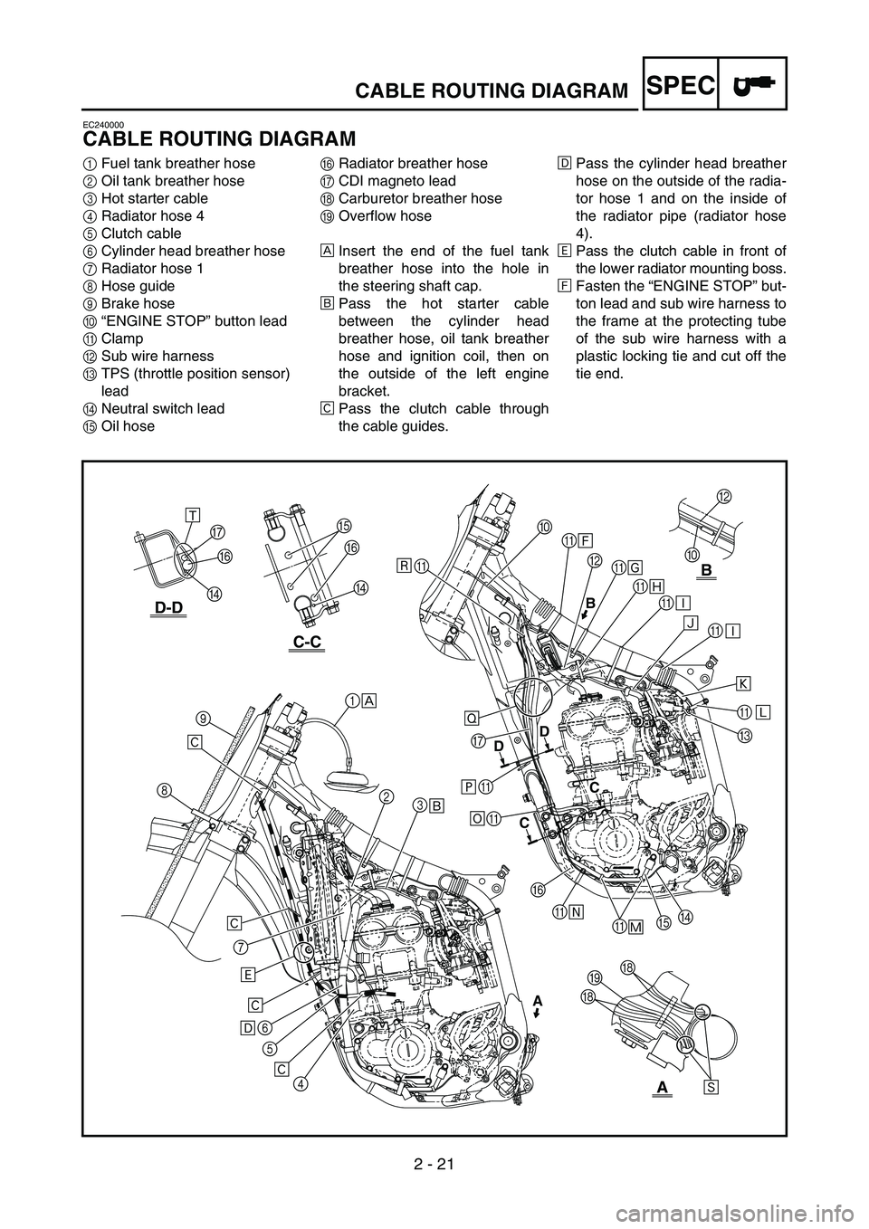
CABLE ROUTING DIAGRAM
1Fuel tank breather hose
2Oil tank breather hose
3Hot starter cable
4Radiator hose 4
5Clutch cable
6Cylinder head breather hose
7Radiator hose 1
8Hose guide
9Brake hose
0“ENGINE STOP” button lead
AClamp
BSub wire harness
CTPS (throttle position sensor)
lead
DNeutral switch lead
EOil hoseFRadiator breather hose
GCDI magneto lead
HCarburetor breather hose
IOverflow hose
ÈInsert the end of the fuel tank
breather hose into the hole in
the steering shaft cap.
ÉPass the hot starter cable
between the cylinder head
breather hose, oil tank breather
hose and ignition coil, then on
the outside of the left engine
bracket.
ÊPass the clutch cable through
the cable guides.ËPass the cylinder head breather
hose on the outside of the radia-
tor hose 1 and on the inside of
the radiator pipe (radiator hose
4).
ÌPass the clutch cable in front of
the lower radiator mounting boss.
ÍFasten the “ENGINE STOP” but-
ton lead and sub wire harness to
the frame at the protecting tube
of the sub wire harness with a
plastic locking tie and cut off the
tie end.
B
0
C-C
D-D
B
A
AB
DD
CC
F
D G
F
D
A
G
A
A
F
AE
A
DC A A A A B A 0
1
2
3
4 5 6 7 89
Ì
Ë
ÊÉ ÈÙÍ
Î
Ï
Ð
Ð Ñ
A
Ô Õ Ø
Ú HIH
E Û
Ò
Ö ×
Ê Ê Ê
Ó
Page 131 of 646

2 - 21
SPEC
KABELFÜHRUNGSDIAGRAMME
1Kraftstofftank-Belüftungsschlauch
2Öltank-Belüftungsschlauch
3Warmstartzug
4Kühler-Schlauch 4
5Kupplungszug
6Zylinderkopf-Entlüftungsschlauch
7Kühler-Schlauch 1
8Schlauchführung
9Bremsschlauch
0Kabel des Motorstoppschalters “ENGINE STOP”
AKlemme
BNebenkabelbaum
CDrosselklappensensor-Kabel
DLeerlaufschalter-Kabel
EÖlschlauch
FKühler-Entlüftungsschlauch
GLichtmaschinen-Kabel
HVergaser-Entlüftungsschlauch
IÜberlaufschlauch
ÈDes Ende des Kraftstofftank-Belüftungs-
schlauchs durch die Bohrung in der Lenkkopf-
Abdeckung stecken.
ÉDen Warmstartzug zwischen dem Zylinderkopf-
Entlüftungsschlauch, dem Öltank-Belüftungs-
schlauch und der Zündspule führen und dann an
der Außenseite der linken Motorhalterung ent-
langführen.
ÊDen Kupplungszug durch die Kabelführungen
leiten.
ËDen Zylinderkopf-Entlüftungsschlauch über den
Kühlerschlauch 1 und das Kühlerrohr (Kühler-
schlauch 4) führen.
ÌDen Kupplungszug vor der unteren Kühlerbefe-
stigung führen.
ÍDas Kabel des Motorstoppschalters “ENGINE
STOP” und den Nebenkabelbaum im Bereich
der Nebenkabelbaum-Schutzhülle mit einem
Kabelbinder am Rahmen befestigen und das
Ende abschneiden.
DIAGRAMME D’ACHEMINEMENT DES CABLES
KABELFÜHRUNGSDIAGRAMME
DIAGRAMME
D’ACHEMINEMENT DES CABLES
1Durit de mise à l’air du réservoir de carburant
2Durit de mise à l’air du réservoir d’huile
3Câble de démarrage à chaud
4Durit de radiateur 4
5Câble d’embrayage
6Durit de mise à l’air de la culasse
7Durit de radiateur 1
8Guide de durit
9Durit de frein
0Fil du bouton “ENGINE STOP”
ACollier à pince
BFaisceau de fils secondaire
CFil du capteur de position de papillon des gaz
DFil du contacteur de point mort
EDurit d’huile
FDurit de mise à l’air du radiateur
GFil du volant magnétique CDI
HDurit de mise à l’air du carburateur
IDurit de trop-plein
ÈInsérer l’extrémité de la durit de mise à l’air du réser-
voir de carburant dans le trou du capuchon de l’arbre
de direction.
ÉAcheminer le câble de démarrage à chaud entre la
durit de mise à l’air de la culasse, la durit de mise à
l’air du réservoir d’huile et la bobine d’allumage,
puis à l’extérieur du support de moteur gauche.
ÊAcheminer le câble d’embrayage dans les guide-
câbles.
ËAcheminer la durit de mise à l’air de la culasse à
l’extérieur de la durit de radiateur 1 et à l’intérieur du
tuyau de radiateur (durit de radiateur 4).
ÌAcheminer le câble d’embrayage devant la noix de
montage inférieure du radiateur.
ÍFixer le fil du bouton “ENGINE STOP” et le faisceau
de fils secondaire au cadre au niveau du tube de pro-
tection du faisceau de fils secondaire, à l’aide d’un
collier en plastique. Couper ensuite l’extrémité du
collier.
Page 132 of 646

2 - 22
SPECCABLE ROUTING DIAGRAM
ÎFasten the “ENGINE STOP” but-
ton lead and sub wire harness to
the frame at the protecting tube
for the “ENGINE STOP” button
lead with a plastic locking tie and
cut off the tie end.
ÏFasten the sub wire harness and
hot starter cable to the frame at
the white tape for the sub wire
harness with a plastic locking tie
and cut off the tie end.
ÐFasten the sub wire harness to
the frame with a plastic locking
tie and cut off the tie end.
ÑPass the sub wire harness
between the engine brackets.ÒMake sure that the TPS coupler
does not go outside the chassis.
ÓFasten the TPS lead to the
frame with a plastic band.
ÔFasten the neutral switch lead
and oil hose together with a
plastic locking tie and cut off the
tie end.
ÕFasten the neutral switch lead to
the frame with a plastic band.
ÖFasten the neutral switch lead,
CDI magneto lead and radiator
breather hose to the frame with
a plastic band.×Fasten the neutral switch lead,
CDI magneto lead and radiator
breather hose to the frame with
a plastic locking tie and cut off
the tie end.
ØPass the neutral switch lead,
CDI magneto lead and radiator
breather hose between the radi-
ator and frame.
ÙFasten the neutral switch lead
and CDI magneto lead to the
cable guide at their protecting
tubes with a plastic locking tie
and cut off the tie end.
ÚPass the carburetor breather
hoses and overflow hose so that
all there hoses do not contact
the rear shock absorber.
B
0
C-C
D-D
B
A
AB
DD
CC
F
D G
F
D
A
G
A
A
F
AE
A
DC A A A A B A 0
1
2
3
4 5 6 7 89
Ì
Ë
ÊÉ ÈÙÍ
Î
Ï
Ð
Ð Ñ
A
Ô Õ Ø
Ú HIH
E Û
Ò
Ö ×
Ê Ê Ê
Ó
Page 133 of 646

2 - 22
SPEC
ÎDas Kabel des Motorstoppschalters “ENGINE
STOP” und den Nebenkabelbaum im Bereich
der Schutzhülle vom Kabel des Motorstopp-
schalters “ENGINE STOP” mit einem Kabelbin-
der am Rahmen befestigen und das Ende
abschneiden.
ÏDen Nebenkabelbaum und den Warmstartzug
an der mit weißem Band am Nebenkabelbaum
markierten Stelle mit einem Kabelbinder am
Rahmen befestigen und das Ende abschneiden.
ÐDen Nebenkabelbaum mit einem Kabelbinder
am Rahmen befestigen und das Ende abschnei-
den.
ÑDen Nebenkabelbaum zwischen die Motorhalte-
rungen führen.
ÒSicherstellen, daß der Drosselklappensensor-
Steckverbinder nicht am Fahrgestell herausragt.
ÓDas Drosselklappensensor-Kabel mit einem
Kunststoffbinder am Rahmen befestigen.
ÔDas Leerlaufschalter-Kabel und den Ölschlauch
mit einem Kabelbinder zusammenbinden und
das Ende abschneiden.
ÕDas Leerlaufschalter-Kabel mit einem Kunst-
stoffbinder am Rahmen befestigen.
ÖDas Leerlaufschalter-Kabel, das Lichtmaschi-
nen-Kabel und den Kühler-Entlüftungsschlauch
mit einem Kunststoffbinder am Rahmen befesti-
gen.
×Das Leerlaufschalter-Kabel, das Lichtmaschi-
nen-Kabel und den Kühler-Entlüftungsschlauch
mit einem Kabelbinder am Rahmen befestigen
und das Ende abschneiden.
ØDas Leerlaufschalter-Kabel, das Lichtmaschi-
nen-Kabel und den Kühler-Entlüftungsschlauch
zwischen Kühler und Rahmen führen.
ÙDas Leerlaufschalter-Kabel und das Lichtma-
schinen-Kabel an deren Schutzhüllen mit einem
Kunststoffbinder im Bereich deren Schutzhüllen
an der Kabelführung befestigen und das Ende
abschneiden.
ÚDie Vergaser-Entlüftungs- und Überlaufschläu-
che so führen, daß sie das Federbein nicht
berühren.
DIAGRAMME D’ACHEMINEMENT DES CABLES
KABELFÜHRUNGSDIAGRAMME
ÎFixer le fil du bouton “ENGINE STOP” et le faisceau
de fils secondaire au cadre au niveau du tube de pro-
tection du fil du bouton “ENGINE STOP”, à l’aide
d’un collier en plastique. Couper ensuite l’extrémité
du collier.
ÏFixer le faisceau de fils secondaire et le câble de
démarrage à chaud au cadre au niveau de bande blan-
che du faisceau de fils secondaire, à l’aide d’un col-
lier en plastique. Couper ensuite l’extrémité du
collier.
ÐFixer le faisceau de fils secondaire au cadre à l’aide
d’un collier en plastique et couper l’extrémité du col-
lier.
ÑAcheminer le faisceau de fils secondaire entre les
supports de moteur.
ÒVeiller à ce que la fiche rapide du capteur de position
de papillon des gaz ne sorte pas du châssis.
ÓFixer le fil du capteur de position de papillon des gaz
au cadre à l’aide d’un collier réutilisable.
ÔAttacher ensemble le fil du contacteur de point mort
et la durit d’huile à l’aide d’un collier en plastique et
couper l’extrémité du collier.
ÕFixer le fil du contacteur de point mort au cadre à
l’aide d’un collier réutilisable.
ÖFixer le fil du contacteur de point mort, le fil du
volant magnétique CDI et la durit de mise à l’air du
radiateur au cadre à l’aide d’un collier réutilisable.
×Fixer le fil du contacteur de point mort, le fil du
volant magnétique CDI et la durit de mise à l’air du
radiateur au cadre à l’aide d’un collier en plastique et
couper l’extrémité du collier.
ØAcheminer le fil du contacteur de point mort, le fil du
volant magnétique CDI et la durit de mise à l’air du
radiateur entre le radiateur et le cadre.
ÙFixer le fil du contacteur de point mort et le fil du
volant magnétique CDI au guide-câbles au niveau de
leurs tubes de protection, à l’aide d’un collier en plas-
tique. Couper ensuite l’extrémité du collier.
ÚAcheminer les durits de mise à l’air du carburateur et
la durit de trop-plein de manière à ce qu’aucune
d’elles n’entre en contact avec l’amortisseur arrière.
Page 140 of 646

2 - 26
SPECCABLE ROUTING DIAGRAM
1Throttle cable
2Fuel tank breather hose
3Clamp
4Clutch cable
5Hot starter cable
6“ENGINE STOP” button lead
7Brake hose
8Hose guideÈFasten the “ENGINE STOP” but-
ton lead to the handlebar with
the plastic band.
ÉPass the brake hose in front of
the number plate.
3
6
40˚±10˚
A
12
3
4
5
6
7
8 È
É
A
Page 141 of 646

2 - 26
SPEC
1Gaszug
2Kraftstofftank-Belüftungsschlauch
3Klemme
4Kupplungszug
5Warmstartzug
6Kabel des Motorstoppschalters “ENGINE STOP”
7Bremsschlauch
8Schlauchführung
ÈDas Kabel des Motorstoppschalters “ENGINE
STOP” mit einem Kunststoffbinder am Lenker
befestigen.
ÉDen Bremsschlauch an der Vorderseite des
Nummernschildes entlangführen.
DIAGRAMME D’ACHEMINEMENT DES CABLES
KABELFÜHRUNGSDIAGRAMME
1Câble des gaz
2Durit de mise à l’air du réservoir de carburant
3Collier à pince
4Câble d’embrayage
5Câble de démarrage à chaud
6Fil du bouton “ENGINE STOP”
7Durit de frein
8Guide de durit
ÈFixer le fil du bouton “ENGINE STOP” au guidon à
l’aide du collier réutilisable.
ÉAcheminer la durit de frein devant la plaque d’identi-
fication.
Page 174 of 646

3 - 15
INSP
ADJ
ENGINE OIL REPLACEMENT
5. Start the engine and let it warm up for sev-
eral minutes.
CAUTION:
When the oil tank is empty, never start the
engine.
6. Idle the engine more than 10 seconds
while keeping the machine upright. Then
stop the engine and add the oil to the maxi-
mum level.
7. Install:
Oil tank cap
ENGINE OIL REPLACEMENT
1. Start the engine and let it warm up for sev-
eral minutes.
2. Stop the engine and place an oil pan under
the drain bolt.
3. Remove:
Oil tank plug 1
Oil filler cap 2
Drain bolt (with gasket) 3
Oil filter drain bolt (O-ring) 4
Drain bolt (with gasket) 5
Drain bolt (with gasket) 6
Drain the crankcase and oil tank (frame)
of its oil.
4. Remove:
Engine skid plate
Engine oil hose clamp 1
Bolt (engine oil hose) 2
Engine oil hose 3
Oil strainer (frame) 4
5. Clean:
Oil strainer (frame)
Page 180 of 646

3 - 18
INSP
ADJIDLE SPEED ADJUSTMENT/
VALVE CLEARANCE ADJUSTMENT
EC35M021
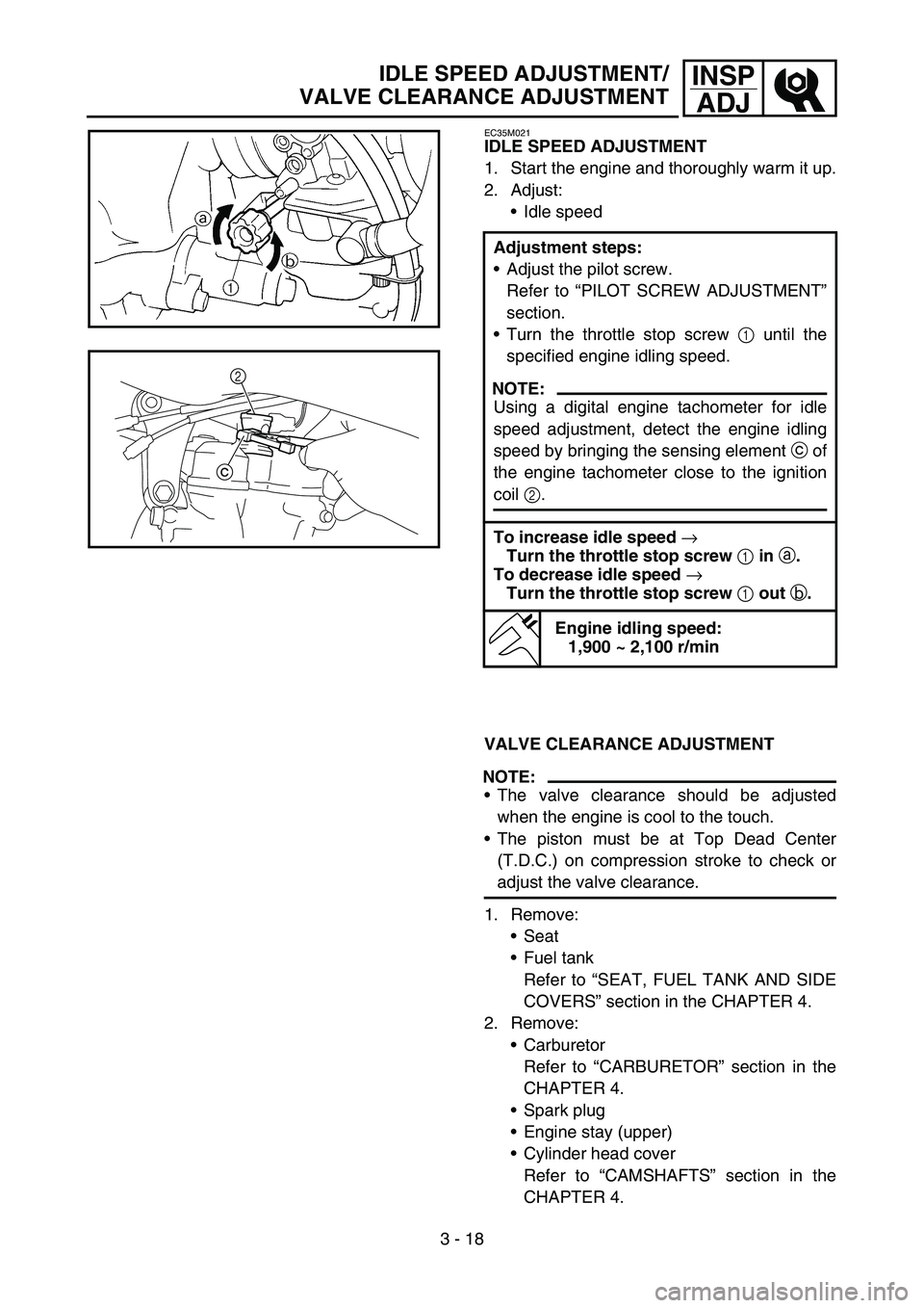
IDLE SPEED ADJUSTMENT
1. Start the engine and thoroughly warm it up.
2. Adjust:
Idle speed
VALVE CLEARANCE ADJUSTMENT
NOTE:
The valve clearance should be adjusted
when the engine is cool to the touch.
The piston must be at Top Dead Center
(T.D.C.) on compression stroke to check or
adjust the valve clearance.
1. Remove:
Seat
Fuel tank
Refer to “SEAT, FUEL TANK AND SIDE
COVERS” section in the CHAPTER 4.
2. Remove:
Carburetor
Refer to “CARBURETOR” section in the
CHAPTER 4.
Spark plug
Engine stay (upper)
Cylinder head cover
Refer to “CAMSHAFTS” section in the
CHAPTER 4. Adjustment steps:
Adjust the pilot screw.
Refer to “PILOT SCREW ADJUSTMENT”
section.
Turn the throttle stop screw 1 until the
specified engine idling speed.
NOTE:
Using a digital engine tachometer for idle
speed adjustment, detect the engine idling
speed by bringing the sensing element c of
the engine tachometer close to the ignition
coil 2.
To increase idle speed
→
Turn the throttle stop screw
1 in
a.
To decrease idle speed
→
Turn the throttle stop screw
1 out
b.
Engine idling speed:
1,900 ~ 2,100 r/min
c2
Page 265 of 646

4 - 12
ENG
2. Kontrollieren:
Hauptdüse 1
Leerlaufdüse 2
Nadeldüse 3
Chokedüse 4
Leerlauf-Luftdüse 5
Ausströmdüse 6
Beschädigt → Erneuern.
Verunreinigt → Reinigen.
HINWEIS:
Zum Reinigen ein Lösungsmittel auf Petrole-
umbasis verwenden. Sämtliche Kanäle und
Düsen mit Druckluft ausblasen.
Niemals einen Draht verwenden.
Nadelventil
1. Kontrollieren:
Nadelventil 1
Ventilsitz 2
Riefig a → Erneuern.
Verstaubt b → Reinigen.
Filter c
Verstopft → Reinigen.
Drosselklappe
1. Kontrollieren:
Leichtgängigkeit
Fest → Instand setzen, ggf. erneuern.
Die Drosselklappe 1 in das Vergaserge-
häuse einsetzen und deren Leichtgängig-
keit kontrollieren.
Düsennadel
1. Kontrollieren:
Düsennadel 1
Verbogen/verschlissen → Erneuern.
Clip-Nut
Spiel vorhanden/verschlissen → Erneu-
ern.
Clipposition
Standard-Clipposition:
4. Nut
CARBURATEUR
VERGASER
2. Contrôler:
Gicleur principal 1
Gicleur de ralenti 2
Gicleur d’aiguille 3
Gicleur de starter 4
Gicleur d’air de ralenti 5
Gicleur de fuite 6
Endommagement → Remplacer.
Encrassé → Nettoyer.
N.B.:
Nettoyer avec un solvant à base de pétrole. Net-
toyer tous les conduits et gicleurs à l’air com-
primé.
Ne jamais utiliser de fil métallique.
Pointeau
1. Contrôler:
Pointeau 1
Siège de pointeau 2
Usure en creux a → Remplacer.
Poussière b → Nettoyer.
Filtre c
Bouché → Nettoyer.
Papillon des gaz
1. Contrôler:
Mouvement
Coincement → Réparer ou remplacer.
Insérer le papillon des gaz 1 dans le corps du
carburateur et contrôler qu’il coulisse libre-
ment.
Aiguille
1. Contrôler:
Aiguille 1
Déformation/usure → Remplacer.
Rainure du clip
Jeu/usure → Remplacer.
Position du clip
Position standard du clip:
Rainure n°4