light YAMAHA YZ450F 2005 Owner's Manual
[x] Cancel search | Manufacturer: YAMAHA, Model Year: 2005, Model line: YZ450F, Model: YAMAHA YZ450F 2005Pages: 646, PDF Size: 16.06 MB
Page 430 of 646

4 - 95
ENGTRANSMISSION, SHIFT CAM AND SHIFT FORK
EC4H3000
REMOVAL POINTS
Shift fork, shaft cam and transmission
1. Remove:
Shift forks
Shift cam
Main axle
Drive axle
NOTE:
Tap lightly on the transmission drive axle and
shift cam with a soft hammer to remove.
Remove assembly carefully. Note the posi-
tion of each part. Pay particular attention to
the location and direction of shift forks.
EC4H4000
INSPECTION
EC4H4200
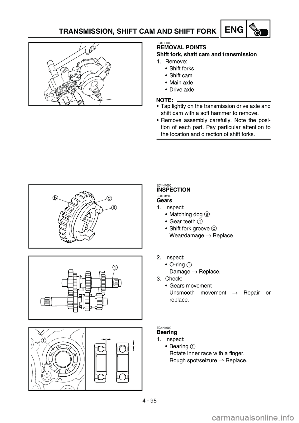
Gears
1. Inspect:
Matching dog a
Gear teeth b
Shift fork groove c
Wear/damage → Replace.
2. Inspect:
O-ring 1
Damage → Replace.
3. Check:
Gears movement
Unsmooth movement → Repair or
replace.
EC4H4600
Bearing
1. Inspect:
Bearing 1
Rotate inner race with a finger.
Rough spot/seizure → Replace.
Page 478 of 646

5 - 21
CHASFRONT BRAKE AND REAR BRAKE
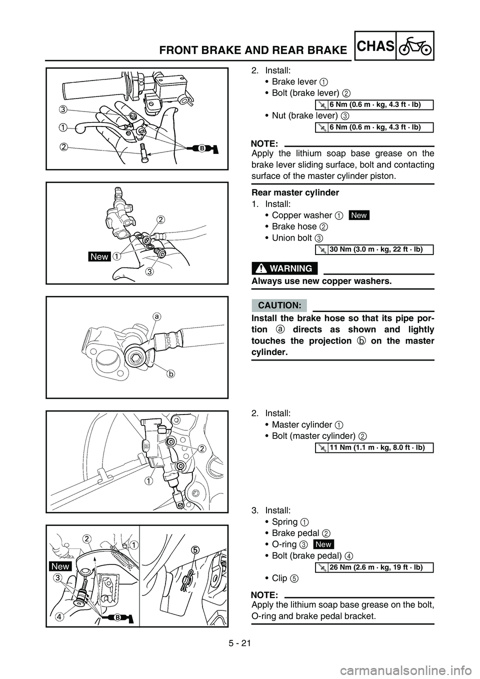
2. Install:
Brake lever 1
Bolt (brake lever) 2
Nut (brake lever) 3
NOTE:
Apply the lithium soap base grease on the
brake lever sliding surface, bolt and contacting
surface of the master cylinder piston.
Rear master cylinder
1. Install:
Copper washer 1
Brake hose 2
Union bolt 3
WARNING
Always use new copper washers.
CAUTION:
Install the brake hose so that its pipe por-
tion
a directs as shown and lightly
touches the projection
b on the master
cylinder.
T R..6 Nm (0.6 m · kg, 4.3 ft · lb)
T R..6 Nm (0.6 m · kg, 4.3 ft · lb)
New
T R..30 Nm (3.0 m · kg, 22 ft · lb)
2. Install:
Master cylinder 1
Bolt (master cylinder) 2
3. Install:
Spring 1
Brake pedal 2
O-ring 3
Bolt (brake pedal) 4
Clip 5
NOTE:
Apply the lithium soap base grease on the bolt,
O-ring and brake pedal bracket.
T R..11 Nm (1.1 m · kg, 8.0 ft · lb)
New
T R..26 Nm (2.6 m · kg, 19 ft · lb)
Page 480 of 646

5 - 22
CHASFRONT BRAKE AND REAR BRAKE
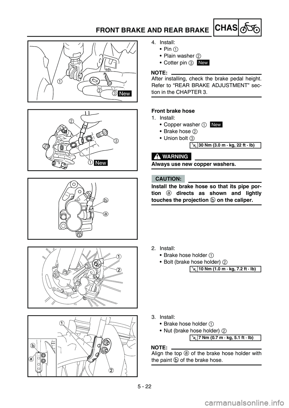
4. Install:
Pin 1
Plain washer 2
Cotter pin 3
NOTE:
After installing, check the brake pedal height.
Refer to “REAR BRAKE ADJUSTMENT” sec-
tion in the CHAPTER 3.
New
Front brake hose
1. Install:
Copper washer 1
Brake hose 2
Union bolt 3
WARNING
Always use new copper washers.
CAUTION:
Install the brake hose so that its pipe por-
tion
a directs as shown and lightly
touches the projection
b on the caliper.
New
T R..30 Nm (3.0 m · kg, 22 ft · lb)
2. Install:
Brake hose holder 1
Bolt (brake hose holder) 2
T R..10 Nm (1.0 m · kg, 7.2 ft · lb)
3. Install:
Brake hose holder 1
Nut (brake hose holder) 2
NOTE:
Align the top a of the brake hose holder with
the paint b of the brake hose.
T R..7 Nm (0.7 m · kg, 5.1 ft · lb)
Page 482 of 646

5 - 23
CHASFRONT BRAKE AND REAR BRAKE
4. Pass the brake hose through the cable
guide 1.
5. Install:
Copper washer 1
Brake hose 2
Union bolt 3
WARNING
Always use new copper washers.
CAUTION:
Install the brake hose so that its pipe por-
tion
a directs as shown and lightly
touches the projection
b on the master
cylinder.
New
T R..30 Nm (3.0 m · kg, 22 ft · lb)
Rear brake hose
1. Install:
Copper washer 1
Brake hose 2
Union bolt 3
WARNING
Always use new copper washers.
CAUTION:
Install the brake hose so that its pipe por-
tion
a directs as shown and lightly
touches the projection
b on the caliper.
New
T R..30 Nm (3.0 m · kg, 22 ft · lb)
Page 600 of 646

7 - 2
TUN
CAUTION:
The carburetor is extremely sensitive to
foreign matter (dirt, sand, water, etc.).
During installation, do not allow foreign
matter to get into the carburetor.
Always handle the carburetor and its
components carefully. Even slight
scratches, bends or damage to carburetor
parts may prevent the carburetor from
functioning correctly. Carefully perform
all servicing with the appropriate tools
and without applying excessive force.
When the engine is stopped or when
riding at no load, do not open and close
the throttle unnecessarily. Otherwise, too
much fuel may be discharged, starting
may become difficult or the engine may
not run well.
After installing the carburetor, check that
the throttle operates correctly and opens
and closes smoothly.
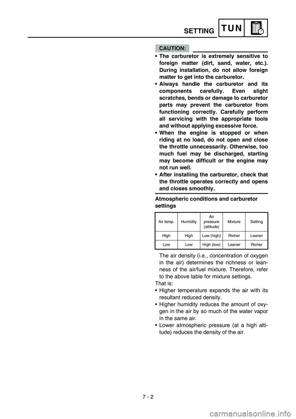
Atmospheric conditions and carburetor
settings
The air density (i.e., concentration of oxygen
in the air) determines the richness or lean-
ness of the air/fuel mixture. Therefore, refer
to the above table for mixture settings.
That is:
Higher temperature expands the air with its
resultant reduced density.
Higher humidity reduces the amount of oxy-
gen in the air by so much of the water vapor
in the same air.
Lower atmospheric pressure (at a high alti-
tude) reduces the density of the air.
Air temp. HumidityAir
pressure
(altitude)Mixture Setting
High High Low (high) Richer Leaner
Low Low High (low) Leaner Richer
SETTING