oil YAMAHA YZ450F 2006 Betriebsanleitungen (in German)
[x] Cancel search | Manufacturer: YAMAHA, Model Year: 2006, Model line: YZ450F, Model: YAMAHA YZ450F 2006Pages: 650, PDF-Größe: 20.71 MB
Page 218 of 650

3 - 36
INSP
ADJ
REAR SHOCK ABSORBER INSPECTION
STANDARD POSITION:
This is the position which is back by the spe-
cific number of clicks from the fully turned-in
position.
* For EUROPE
CAUTION:
Do not force the adjuster past the minimum
or maximum extent of adjustment. The
adjuster may be damaged.
WARNING
Always adjust each front fork to the same
setting. Uneven adjustment can cause poor
handling and loss of stability.
Extent of adjustment:
Maximum Minimum
Fully turned in
position20 clicks out
(from maximum
position)
Standard position:
11 clicks out
*6 clicks out
EC36K000
REAR SHOCK ABSORBER INSPECTION
1. Inspect:
Swingarm smooth action
Abnormal noise/unsmooth action →
Grease the pivoting points or repair the
pivoting points.
Damage/oil leakage → Replace.
Page 229 of 650
INSP
ADJ
CONTROLE DE LA PRESSION DES PNEUS/
CONTROLE ET SERRAGE DES RAYONS/CONTROLE DES ROUES
REIFENLUFTDRUCK KONTROLLIEREN/SPEICHEN KONTROLLIEREN
UND SPANNEN/RÄDER KONTROLLIEREN
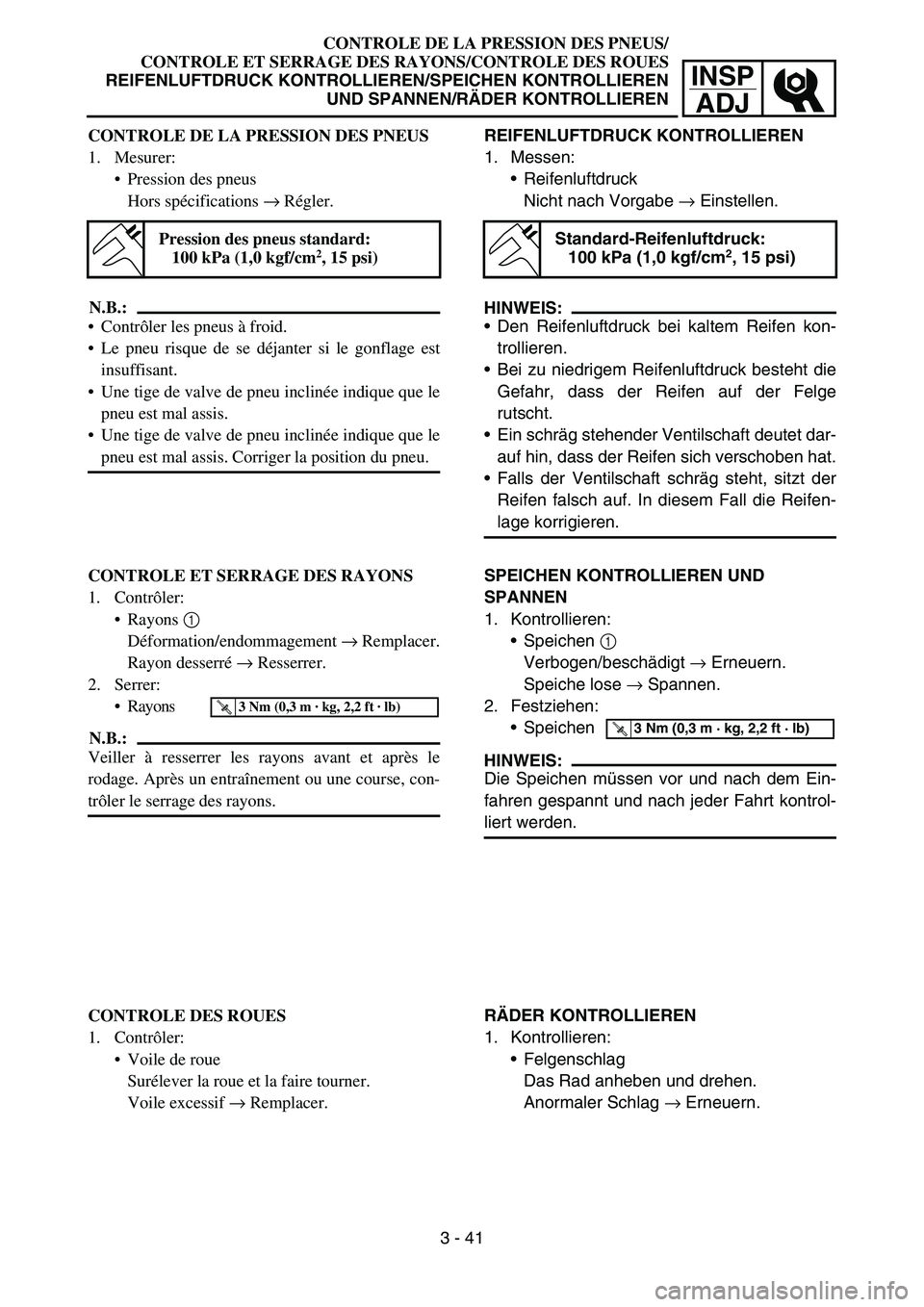
REIFENLUFTDRUCK KONTROLLIEREN
1. Messen:
Reifenluftdruck
Nicht nach Vorgabe → Einstellen.
HINWEIS:
Den Reifenluftdruck bei kaltem Reifen kon-
trollieren.
Bei zu niedrigem Reifenluftdruck besteht die
Gefahr, dass der Reifen auf der Felge
rutscht.
Ein schräg stehender Ventilschaft deutet dar-
auf hin, dass der Reifen sich verschoben hat.
Falls der Ventilschaft schräg steht, sitzt der
Reifen falsch auf. In diesem Fall die Reifen-
lage korrigieren.
Standard-Reifenluftdruck:
100 kPa (1,0 kgf/cm2, 15 psi)
SPEICHEN KONTROLLIEREN UND
SPANNEN
1. Kontrollieren:
Speichen 1
Verbogen/beschädigt → Erneuern.
Speiche lose → Spannen.
2. Festziehen:
Speichen
HINWEIS:
Die Speichen müssen vor und nach dem Ein-
fahren gespannt und nach jeder Fahrt kontrol-
liert werden.
T R..3 Nm (0,3 m · kg, 2,2 ft · lb)
RÄDER KONTROLLIEREN
1. Kontrollieren:
Felgenschlag
Das Rad anheben und drehen.
Anormaler Schlag → Erneuern. CONTROLE DE LA PRESSION DES PNEUS
1. Mesurer:
Pression des pneus
Hors spécifications → Régler.
N.B.:
Contrôler les pneus à froid.
Le pneu risque de se déjanter si le gonflage est
insuffisant.
Une tige de valve de pneu inclinée indique que le
pneu est mal assis.
Une tige de valve de pneu inclinée indique que le
pneu est mal assis. Corriger la position du pneu.
Pression des pneus standard:
100 kPa (1,0 kgf/cm2, 15 psi)
CONTROLE ET SERRAGE DES RAYONS
1. Contrôler:
Rayons 1
Déformation/endommagement → Remplacer.
Rayon desserré → Resserrer.
2. Serrer:
Rayons
N.B.:
Veiller à resserrer les rayons avant et après le
rodage. Après un entraînement ou une course, con-
trôler le serrage des rayons.
T R..3 Nm (0,3 m · kg, 2,2 ft · lb)
CONTROLE DES ROUES
1. Contrôler:
Voile de roue
Surélever la roue et la faire tourner.
Voile excessif → Remplacer.
3 - 41
Page 236 of 650
3 - 45
INSP
ADJ
LUBRICATION
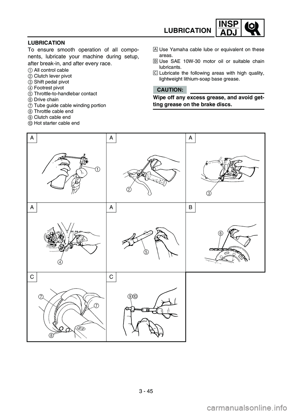
LUBRICATION
To ensure smooth operation of all compo-
nents, lubricate your machine during setup,
after break-in, and after every race.
1All control cable
2Clutch lever pivot
3Shift pedal pivot
4Footrest pivot
5Throttle-to-handlebar contact
6Drive chain
7Tube guide cable winding portion
8Throttle cable end
9Clutch cable end
0Hot starter cable endÈUse Yamaha cable lube or equivalent on these
areas.
ÉUse SAE 10W-30 motor oil or suitable chain
lubricants.
ÊLubricate the following areas with high quality,
lightweight lithium-soap base grease.
CAUTION:
Wipe off any excess grease, and avoid get-
ting grease on the brake discs.
AAA
AAB
CC
Page 240 of 650
3 - 47
INSP
ADJ
IGNITION TIMING CHECK
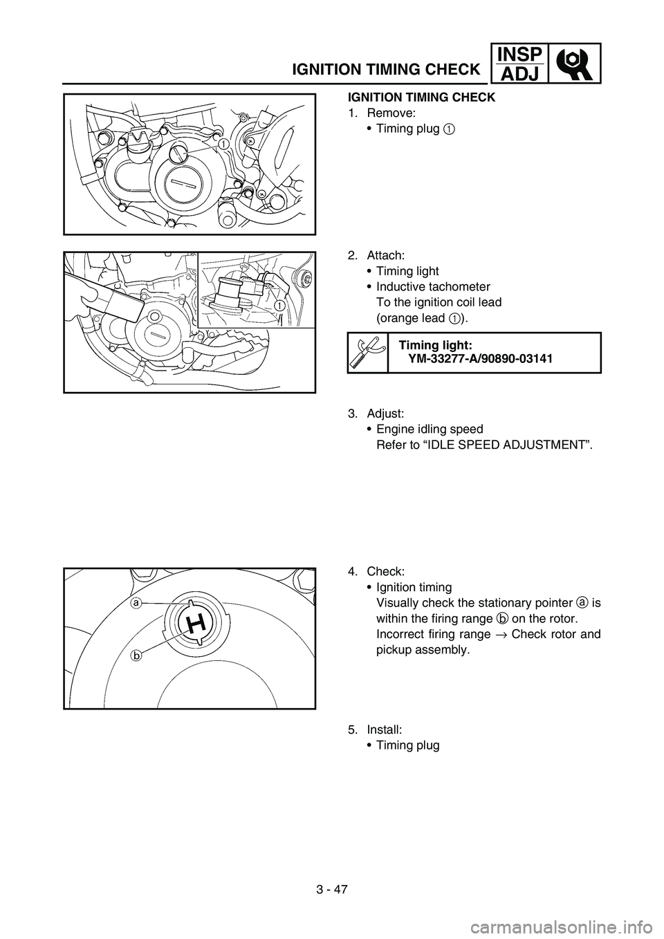
IGNITION TIMING CHECK
1. Remove:
Timing plug 1
2. Attach:
Timing light
Inductive tachometer
To the ignition coil lead
(orange lead 1).
Timing light:
YM-33277-A/90890-03141
3. Adjust:
Engine idling speed
Refer to “IDLE SPEED ADJUSTMENT”.
4. Check:
Ignition timing
Visually check the stationary pointer a is
within the firing range b on the rotor.
Incorrect firing range → Check rotor and
pickup assembly.
5. Install:
Timing plug
Page 294 of 650
4 - 27
ENGCAMSHAFTS
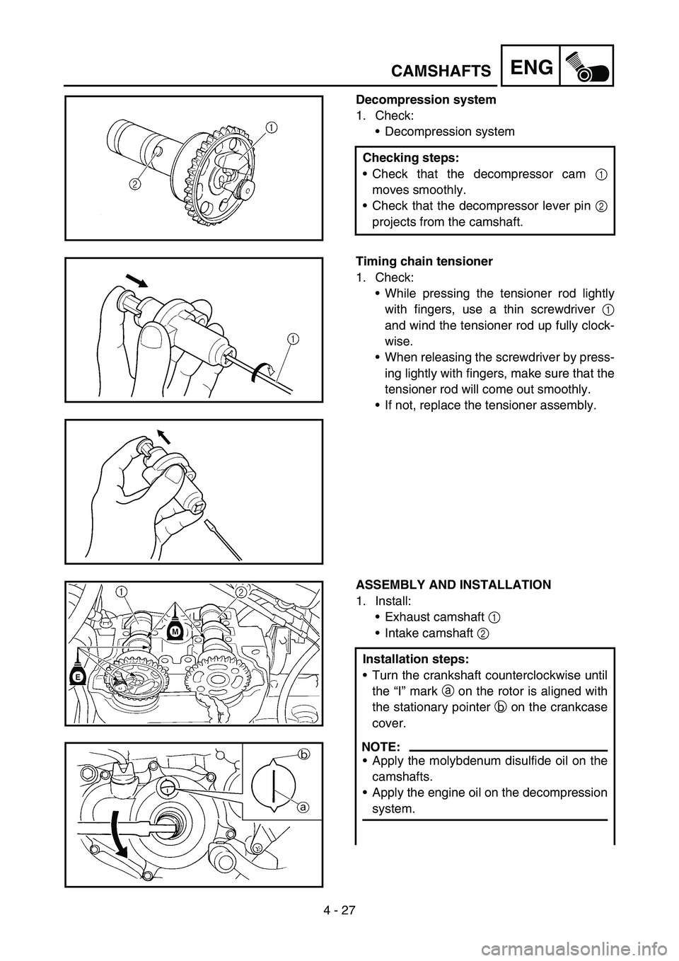
Decompression system
1. Check:
Decompression system
Checking steps:
Check that the decompressor cam 1
moves smoothly.
Check that the decompressor lever pin 2
projects from the camshaft.
Timing chain tensioner
1. Check:
While pressing the tensioner rod lightly
with fingers, use a thin screwdriver 1
and wind the tensioner rod up fully clock-
wise.
When releasing the screwdriver by press-
ing lightly with fingers, make sure that the
tensioner rod will come out smoothly.
If not, replace the tensioner assembly.
ASSEMBLY AND INSTALLATION
1. Install:
Exhaust camshaft 1
Intake camshaft 2
Installation steps:
Turn the crankshaft counterclockwise until
the “I” mark a on the rotor is aligned with
the stationary pointer b on the crankcase
cover.
NOTE:
Apply the molybdenum disulfide oil on the
camshafts.
Apply the engine oil on the decompression
system.
Page 296 of 650
4 - 28
ENGCAMSHAFTS
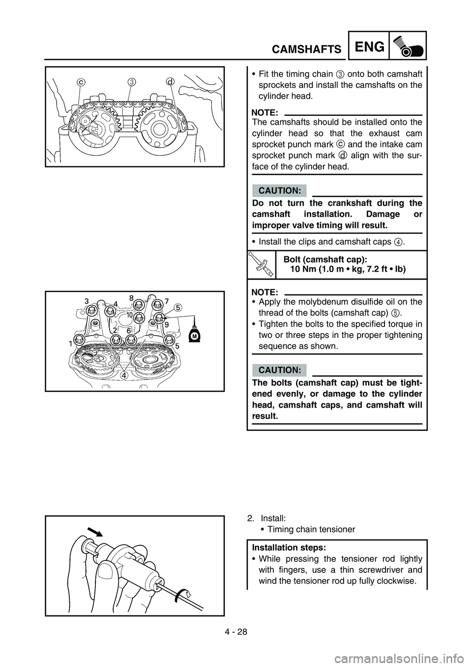
Fit the timing chain 3 onto both camshaft
sprockets and install the camshafts on the
cylinder head.
NOTE:
The camshafts should be installed onto the
cylinder head so that the exhaust cam
sprocket punch mark c and the intake cam
sprocket punch mark d align with the sur-
face of the cylinder head.
CAUTION:
Do not turn the crankshaft during the
camshaft installation. Damage or
improper valve timing will result.
Install the clips and camshaft caps 4.
T R..
Bolt (camshaft cap):
10 Nm (1.0 m kg, 7.2 ft lb)
NOTE:
Apply the molybdenum disulfide oil on the
thread of the bolts (camshaft cap) 5.
Tighten the bolts to the specified torque in
two or three steps in the proper tightening
sequence as shown.
CAUTION:
The bolts (camshaft cap) must be tight-
ened evenly, or damage to the cylinder
head, camshaft caps, and camshaft will
result.
2. Install:
Timing chain tensioner
Installation steps:
While pressing the tensioner rod lightly
with fingers, use a thin screwdriver and
wind the tensioner rod up fully clockwise.
Page 316 of 650
4 - 38
ENGVALVES AND VALVE SPRINGS
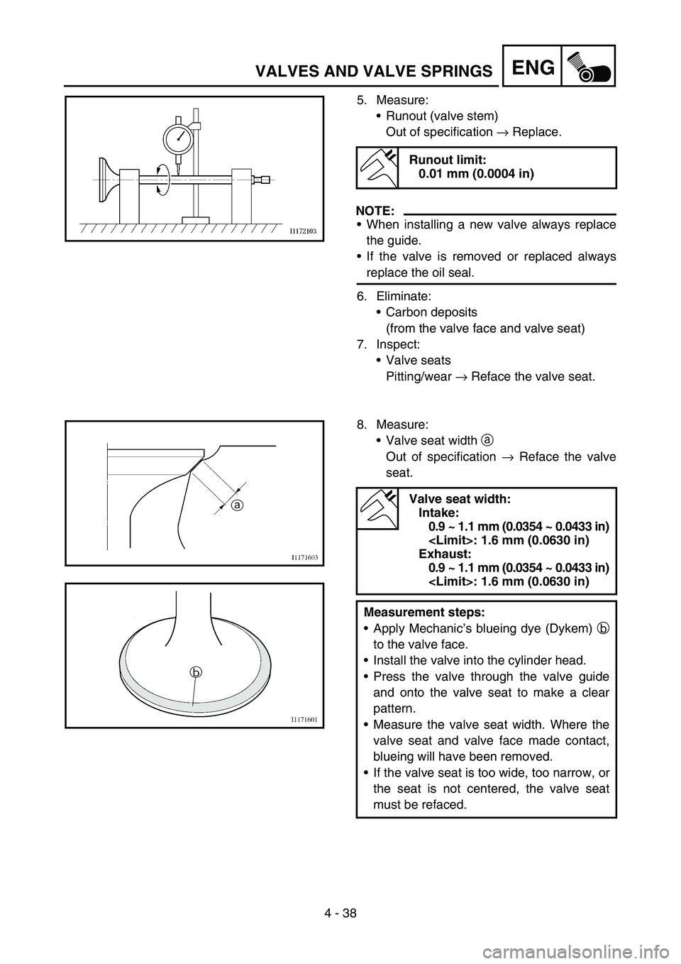
5. Measure:
Runout (valve stem)
Out of specification → Replace.
NOTE:
When installing a new valve always replace
the guide.
If the valve is removed or replaced always
replace the oil seal.
6. Eliminate:
Carbon deposits
(from the valve face and valve seat)
7. Inspect:
Valve seats
Pitting/wear → Reface the valve seat.
Runout limit:
0.01 mm (0.0004 in)
8. Measure:
Valve seat width a
Out of specification → Reface the valve
seat.
Valve seat width:
Intake:
0.9 ~ 1.1 mm (0.0354 ~ 0.0433 in)
Exhaust:
0.9 ~ 1.1 mm (0.0354 ~ 0.0433 in)
Measurement steps:
Apply Mechanic’s blueing dye (Dykem) b
to the valve face.
Install the valve into the cylinder head.
Press the valve through the valve guide
and onto the valve seat to make a clear
pattern.
Measure the valve seat width. Where the
valve seat and valve face made contact,
blueing will have been removed.
If the valve seat is too wide, too narrow, or
the seat is not centered, the valve seat
must be refaced.
Page 318 of 650
4 - 39
ENGVALVES AND VALVE SPRINGS
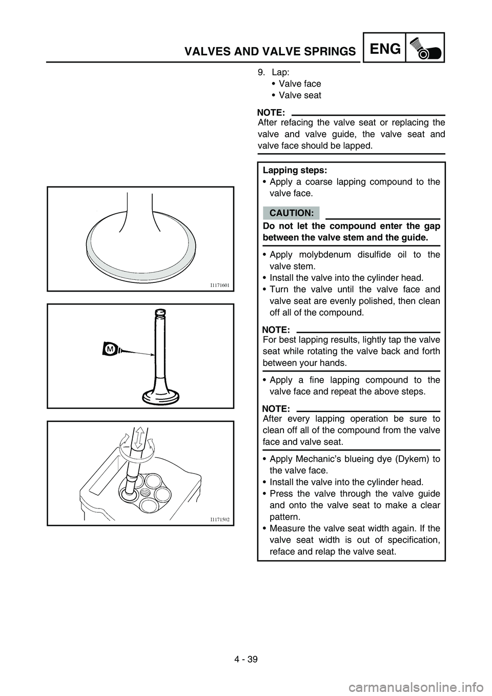
9. Lap:
Valve face
Valve seat
NOTE:
After refacing the valve seat or replacing the
valve and valve guide, the valve seat and
valve face should be lapped.
Lapping steps:
Apply a coarse lapping compound to the
valve face.
CAUTION:
Do not let the compound enter the gap
between the valve stem and the guide.
Apply molybdenum disulfide oil to the
valve stem.
Install the valve into the cylinder head.
Turn the valve until the valve face and
valve seat are evenly polished, then clean
off all of the compound.
NOTE:
For best lapping results, lightly tap the valve
seat while rotating the valve back and forth
between your hands.
Apply a fine lapping compound to the
valve face and repeat the above steps.
NOTE:
After every lapping operation be sure to
clean off all of the compound from the valve
face and valve seat.
Apply Mechanic’s blueing dye (Dykem) to
the valve face.
Install the valve into the cylinder head.
Press the valve through the valve guide
and onto the valve seat to make a clear
pattern.
Measure the valve seat width again. If the
valve seat width is out of specification,
reface and relap the valve seat.
Page 322 of 650
4 - 41
ENGVALVES AND VALVE SPRINGS
ASSEMBLY AND INSTALLATION
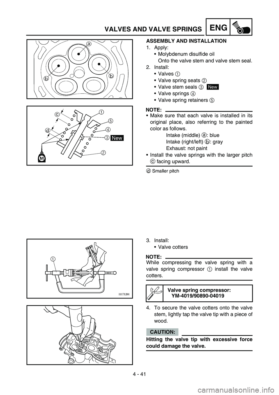
1. Apply:
Molybdenum disulfide oil
Onto the valve stem and valve stem seal.
2. Install:
Valves 1
Valve spring seats 2
Valve stem seals 3
Valve springs 4
Valve spring retainers 5
NOTE:
Make sure that each valve is installed in its
original place, also referring to the painted
color as follows.
Intake (middle) a: blue
Intake (right/left) b: gray
Exhaust: not paint
Install the valve springs with the larger pitch
c facing upward.
dSmaller pitch
New
3. Install:
Valve cotters
NOTE:
While compressing the valve spring with a
valve spring compressor 1 install the valve
cotters.
4. To secure the valve cotters onto the valve
stem, lightly tap the valve tip with a piece of
wood.
CAUTION:
Hitting the valve tip with excessive force
could damage the valve.
Valve spring compressor:
YM-4019/90890-04019
Page 324 of 650
4 - 42
ENGVALVES AND VALVE SPRINGS
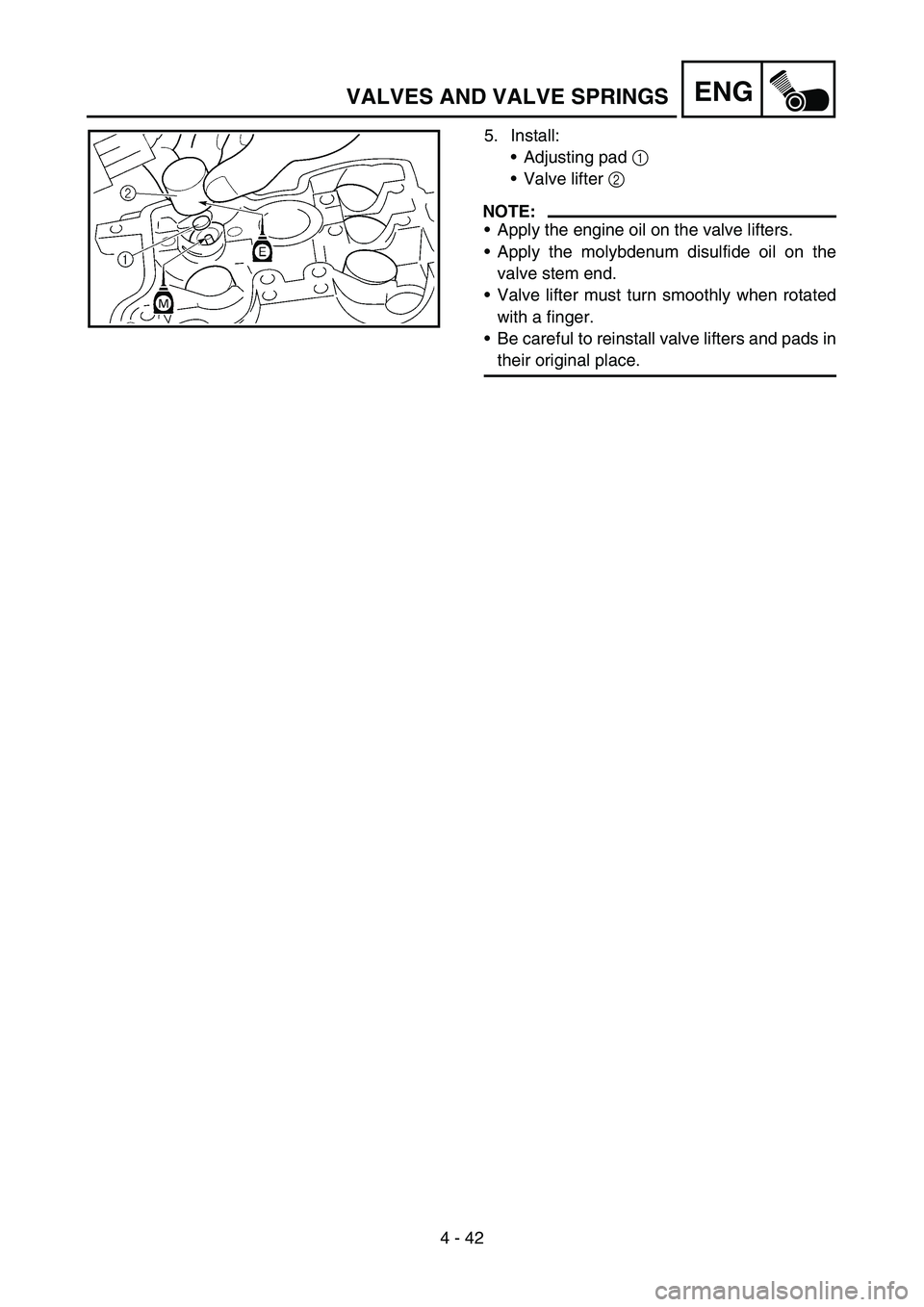
5. Install:
Adjusting pad 1
Valve lifter 2
NOTE:
Apply the engine oil on the valve lifters.
Apply the molybdenum disulfide oil on the
valve stem end.
Valve lifter must turn smoothly when rotated
with a finger.
Be careful to reinstall valve lifters and pads in
their original place.