check oil YAMAHA YZ450F 2006 User Guide
[x] Cancel search | Manufacturer: YAMAHA, Model Year: 2006, Model line: YZ450F, Model: YAMAHA YZ450F 2006Pages: 650, PDF Size: 20.71 MB
Page 170 of 650

3 - 13
INSP
ADJ
7. Install:
Air filter element 1
Washer
Fitting bolt
NOTE:
Align the projection a on filter guide with the
hole b in air filter case.
T R..2 Nm (0.2 m · kg, 1.4 ft · lb)
ENGINE OIL LEVEL INSPECTION
1. Stand the machine on a level surface.
NOTE:
When checking the oil level make sure that
the machine is upright.
Place the machine on a suitable stand.
WARNING
Never remove the oil tank cap just after
high speed operation. The heated oil could
spurt out. causing danger. Wait until the oil
cools down to approximately 70 °C (158 °F).
2. Idle the engine more than 3 minutes while
keeping the machine upright. Then stop the
engine and inspect the oil level.
3. Remove:
Oil tank cap 1
ENGINE OIL LEVEL INSPECTION
Page 172 of 650

3 - 14
INSP
ADJ
ENGINE OIL LEVEL INSPECTION
4. Inspect:
Oil level
Remove the oil tank cap and check that
engine oil is above the level mark a.
Below the level mark a → Add oil above
the level mark a.
Above the level mark b → Remove the
check bolt 1 and drain the oil until it
stops coming out.
NOTE:
When inspecting the oil level, do not screw the
oil level gauge into the oil tank.
Insert the gauge lightly.
(For USA and CDN)
CAUTION:
Do not add any chemical additives.
Engine oil also lubricates the clutch and
additives could cause clutch slippage.
Do not allow foreign material to enter the
crankcase.
(Except for USA and CDN)
Recommended oil:
At 5 °C (40 °F) or higher
È
Yamalube 4 (20W-40) or SAE
20W-40 type SG motor oil
(Non-Friction modified)
At 15 °C (60 °F) or lower
É
Yamalube 4 (10W-30) or SAE
10W-30 type SG motor oil
(Non-Friction modified)
and/or
Yamalube 4-R (15W-50)
(Non-Friction modified)
Recommended oil:
Refer to the following chart for
selection of oils which are
suited to the atmospheric
temperatures.
Recommended engine oil classi-
fication:
API STANDARD:
API “SG” or higher grade
(Designed primarily for
motorcycles)
-20
-4-10
140
3010
5020
6830
8640 50
104
122 ˚CTemp.
˚F
10W-30
10W-40
20W-40
20W-50
15W-40
Page 176 of 650

3 - 16
INSP
ADJ
ENGINE OIL REPLACEMENT
4. If the oil filter is to be replaced during this
oil change, remove the following parts and
reinstall them.
Replacement steps:
Remove the oil filter cover 1 and oil filter
element 2.
Check the O-rings 3, if cracked or dam-
aged, replace them with a new one.
Install the oil filter element and oil filter
cover.
T R..
Oil filter cover:
10 Nm (1.0 m kg, 7.2 ft lb)
5. Install:
Gaskets
Oil filter drain bolt
Drain bolt (crankcase right)
Drain bolt (crankcase left)
New
T R..10 Nm (1.0 m · kg, 7.2 ft · lb)
T R..20 Nm (2.0 m · kg, 14 ft · lb)
T R..20 Nm (2.0 m · kg, 14 ft · lb)
6. Fill:
Crankcase
Oil quantity:
Periodic oil change:
0.95 L (0.84 Imp qt, 1.00 US qt)
With oil filter replacement:
1.0 L (0.88 Imp qt, 1.06 US qt)
Total amount:
1.2 L (1.06 Imp qt, 1.27 US qt)
Page 178 of 650

3 - 17
INSP
ADJ
PILOT SCREW ADJUSTMENT
7. Install:
Oil filler cap
8. Inspect:
Engine (for oil leaks)
Oil level
Refer to “ENGINE OIL LEVEL INSPEC-
TION”.
9. Check:
Oil pressure
Checking steps:
Slightly loosen the oil gallery bolt 1.
Start the engine and keep it idling until oil
starts to seep from the oil gallery bolt. If no
oil comes out after one minute, turn the
engine off so it will not seize.
Check oil passages, oil filter and oil pump
for damage or leakage.
Start the engine after solving the prob-
lem(s) and recheck the oil pressure.
Tighten the oil gallery bolt to specification.
T R..
Oil gallery bolt:
10 Nm (1.0 m kg, 7.2 ft lb)
PILOT SCREW ADJUSTMENT
1. Adjust:
Pilot screw 1
Adjusting steps:
NOTE:
To optimize the fuel flow at a smaller throttle
opening, each machine’s pilot screw has
been individually set at the factory. Before
adjusting the pilot screw, turn it in fully and
count the number of turns. Record this num-
ber as the factory-set number of turns out.
Turn in the pilot screw until it is lightly
seated.
Turn out the pilot screw by the factory-set
number of turns.
Pilot screw (example):
2-1/8 turns out
Page 180 of 650

3 - 18
INSP
ADJIDLE SPEED ADJUSTMENT/
VALVE CLEARANCE ADJUSTMENT
EC35M021
IDLE SPEED ADJUSTMENT
1. Start the engine and thoroughly warm it up.
2. Adjust:
Idle speed
VALVE CLEARANCE ADJUSTMENT
NOTE:
The valve clearance should be adjusted
when the engine is cool to the touch.
The piston must be at Top Dead Center
(T.D.C.) on compression stroke to check or
adjust the valve clearance.
1. Remove:
Seat
Fuel tank
Refer to “SEAT, FUEL TANK AND SIDE
COVERS” section in the CHAPTER 4.
2. Remove:
Spark plug
Engine upper bracket
Hot starter plunger
Refer to “CARBURETOR” section in the
CHAPTER 4.
Cylinder head cover
Refer to “CAMSHAFTS” section in the
CHAPTER 4. Adjustment steps:
Adjust the pilot screw.
Refer to “PILOT SCREW ADJUSTMENT”
section.
Turn the throttle stop screw 1 until the
specified engine idling speed.
NOTE:
Using a digital engine tachometer for idle
speed adjustment, detect the engine idling
speed by bringing the sensing element c of
the engine tachometer close to the ignition
coil 2.
To increase idle speed
→
Turn the throttle stop screw
1 in
a.
To decrease idle speed
→
Turn the throttle stop screw
1 out
b.
Engine idling speed:
1,900 ~ 2,100 r/min
c2
Page 210 of 650

3 - 32
INSP
ADJ
DRIVE CHAIN SLACK ADJUSTMENT
4. Check:
Drive chain stiffness a
Clean and oil the chain and hold as illus-
trated.
Stiff → Replace drive chain.
5. Install:
Drive chain 1
Joint 2
Master link clip 3
CAUTION:
Be sure to install the master link clip to the
direction as shown.
aTurning direction
New
6. Lubricate:
Drive chain
Drive chain lubricant:
SAE 10W-30 motor oil or
suitable chain lubricants
DRIVE CHAIN SLACK ADJUSTMENT
1. Elevate the rear wheel by placing the suit-
able stand under the engine.
2. Check:
Drive chain slack a
Above the seal guard installation bolt.
Out of specification → Adjust.
NOTE:
Before checking and/or adjusting, rotate the
rear wheel through several revolutions and
check the slack several times to find the tight-
est point. Check and/or adjust chain slack with
rear wheel in this “tight chain” position.
Drive chain slack:
48 ~ 58 mm (1.9 ~ 2.3 in)
Page 240 of 650
3 - 47
INSP
ADJ
IGNITION TIMING CHECK
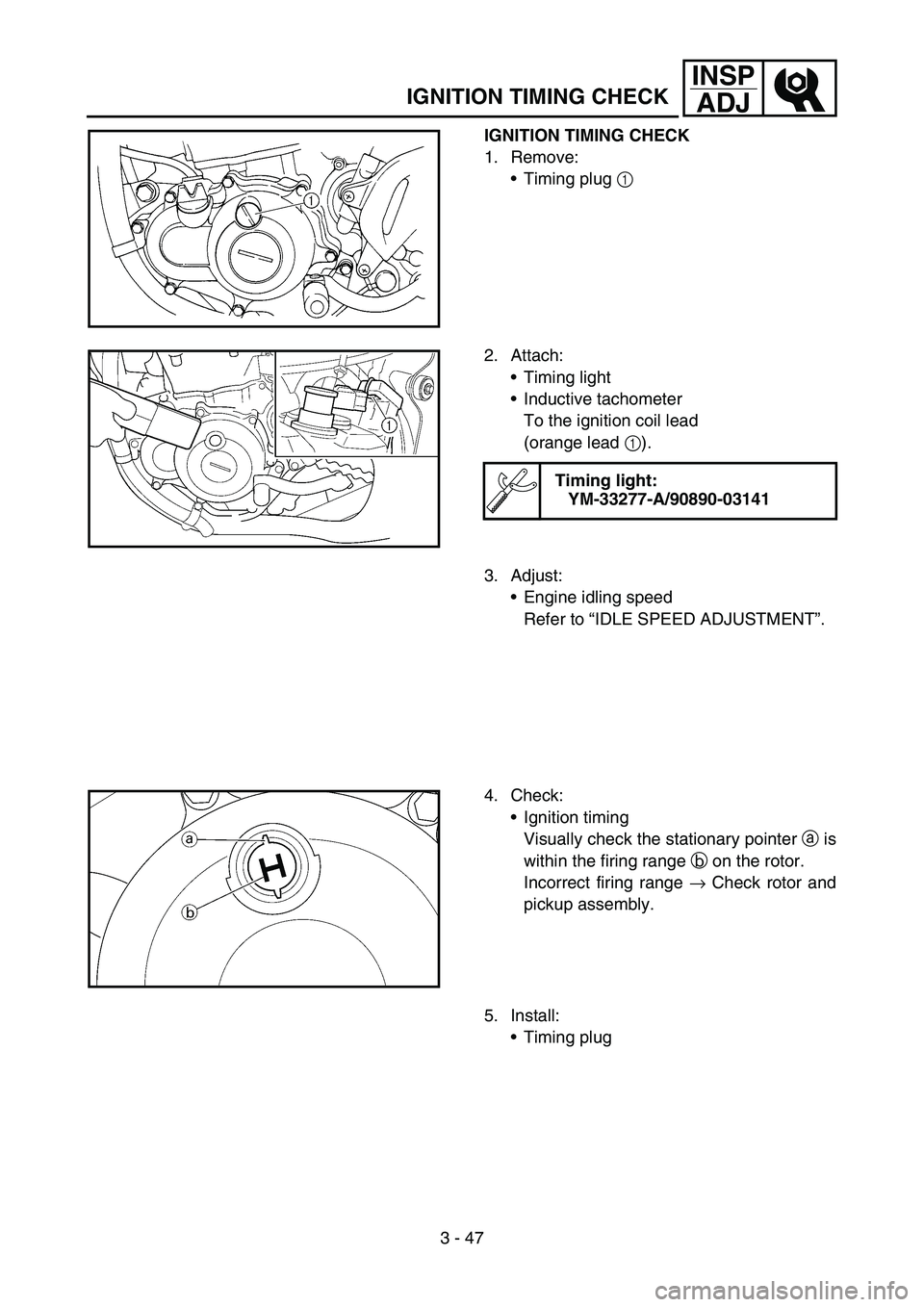
IGNITION TIMING CHECK
1. Remove:
Timing plug 1
2. Attach:
Timing light
Inductive tachometer
To the ignition coil lead
(orange lead 1).
Timing light:
YM-33277-A/90890-03141
3. Adjust:
Engine idling speed
Refer to “IDLE SPEED ADJUSTMENT”.
4. Check:
Ignition timing
Visually check the stationary pointer a is
within the firing range b on the rotor.
Incorrect firing range → Check rotor and
pickup assembly.
5. Install:
Timing plug
Page 294 of 650
4 - 27
ENGCAMSHAFTS
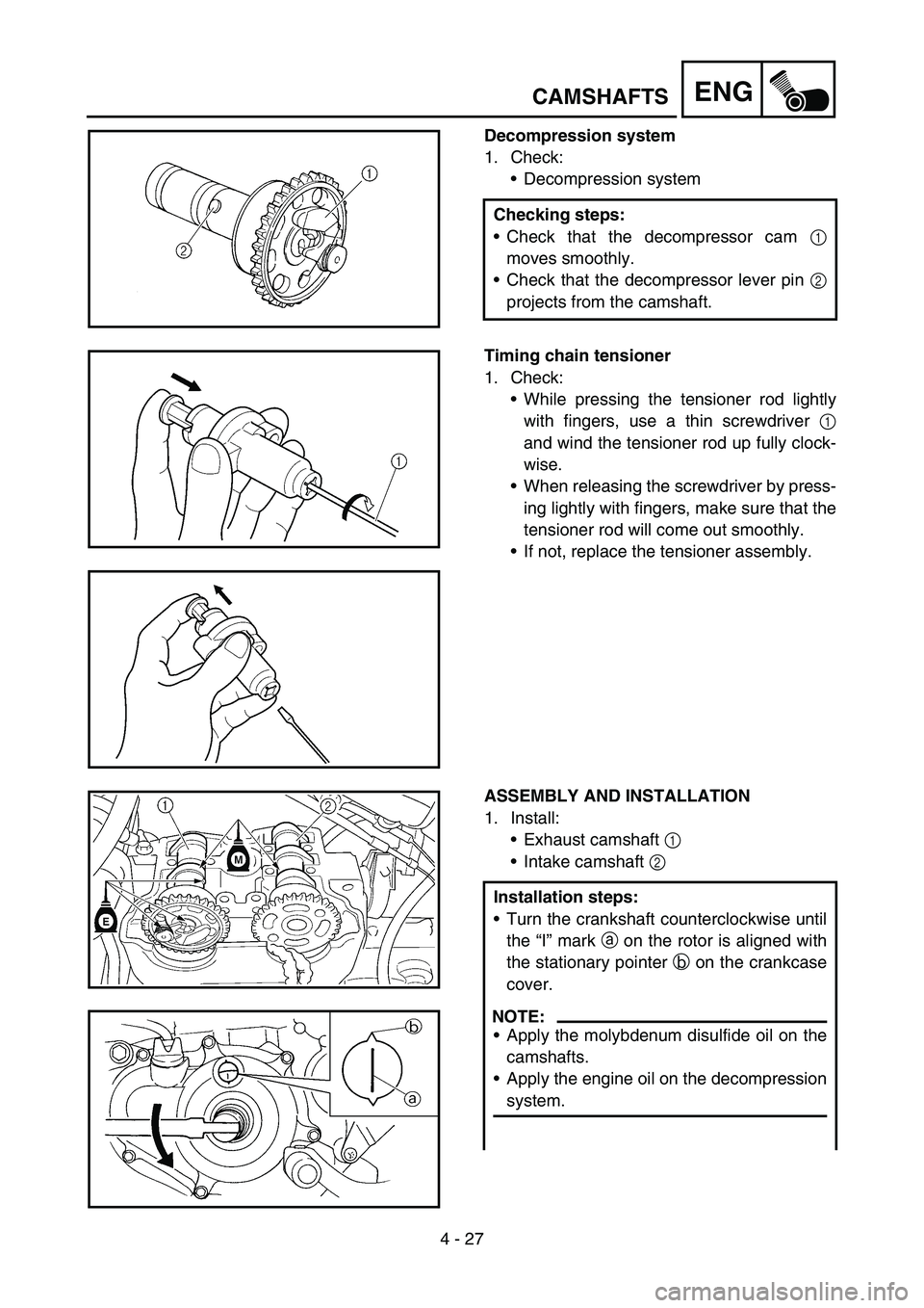
Decompression system
1. Check:
Decompression system
Checking steps:
Check that the decompressor cam 1
moves smoothly.
Check that the decompressor lever pin 2
projects from the camshaft.
Timing chain tensioner
1. Check:
While pressing the tensioner rod lightly
with fingers, use a thin screwdriver 1
and wind the tensioner rod up fully clock-
wise.
When releasing the screwdriver by press-
ing lightly with fingers, make sure that the
tensioner rod will come out smoothly.
If not, replace the tensioner assembly.
ASSEMBLY AND INSTALLATION
1. Install:
Exhaust camshaft 1
Intake camshaft 2
Installation steps:
Turn the crankshaft counterclockwise until
the “I” mark a on the rotor is aligned with
the stationary pointer b on the crankcase
cover.
NOTE:
Apply the molybdenum disulfide oil on the
camshafts.
Apply the engine oil on the decompression
system.
Page 376 of 650

4 - 68
ENGOIL PUMP
INSPECTION
Oil pump
1. Inspect:
Oil pump drive gear
Oil pump driven gear
Rotor housing
Oil pump cover
Cracks/wear/damage → Replace.
2. Measure:
Tip clearance a
Between the inner rotor 1 and the outer
rotor 2.
Tip clearance b
Between the outer rotor 2 and the rotor
housing 3.
Out of specification → Replace the oil
pump.
Tip clearance
a:
0.12 mm or less
(0.0047 in or less)
Tip clearance
b:
0.09 ~ 0.17 mm (0.0035 ~ 0.0067 in)
Side clearance
c:
0.03 ~ 0.10 mm (0.0012 ~ 0.0039 in)
3. Check:
Unsmooth → Repeat steps #1 and #2 or
replace the defective parts.
ASSEMBLY AND INSTALLATION
Oil pump
1. Install:
Oil pump drive shaft 1
Washer 2
Pin 3
Inner rotor 1 4
NOTE:
Apply the engine oil on the oil pump drive
shaft and inner rotor 1.
Fit the pin into the groove in the inner rotor 1.
Page 426 of 650

4 - 93
ENGCRANKCASE AND CRANKSHAFT
NOTE:
Hold the connecting rod at top dead center
with one hand while turning the nut of the
installing tool with the other. Operate the
installing tool until the crankshaft bottoms
against the bearing.
Before installing the crankshaft, clean the
contacting surface of crankcase.
CAUTION:
Do not use a hammer to drive in the crank-
shaft.
2. Check:
Shifter operation
Transmission operation
Unsmooth operation → Repair.
3. Install:
Oil strainer 1
Bolt (oil strainer) 2
4. Apply:
Sealant
On the crankcase (right).
NOTE:
Clean the contacting surface of crankcase (left
and right) before applying the sealant.
YAMAHA Bond No. 1215
(ThreeBond® No. 1215):
90890-85505
T R..10 Nm (1.0 m · kg, 7.2 ft · lb)