bolt YAMAHA YZ450F 2006 Owners Manual
[x] Cancel search | Manufacturer: YAMAHA, Model Year: 2006, Model line: YZ450F, Model: YAMAHA YZ450F 2006Pages: 650, PDF Size: 20.71 MB
Page 26 of 650
GEN
INFO
1 - 1
DESCRIPTION
EC100000
GENERAL INFORMATION
EC110000
DESCRIPTION
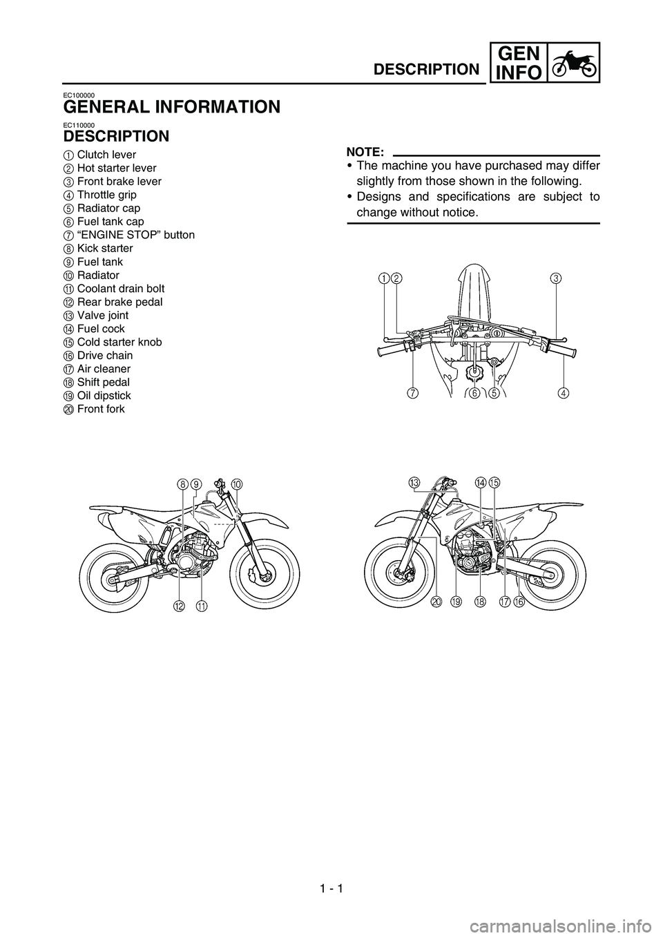
1Clutch lever
2Hot starter lever
3Front brake lever
4Throttle grip
5Radiator cap
6Fuel tank cap
7“ENGINE STOP” button
8Kick starter
9Fuel tank
0Radiator
ACoolant drain bolt
BRear brake pedal
CValve joint
DFuel cock
ECold starter knob
FDrive chain
GAir cleaner
HShift pedal
IOil dipstick
JFront forkNOTE:
The machine you have purchased may differ
slightly from those shown in the following.
Designs and specifications are subject to
change without notice.
Page 32 of 650

1 - 4
GEN
INFO
IMPORTANT INFORMATION
EC132000
ALL REPLACEMENT PARTS
1. We recommend to use Yamaha genuine
parts for all replacements. Use oil and/or
grease recommended by Yamaha for
assembly and adjustment.
EC133000
GASKETS, OIL SEALS AND O-RINGS
1. All gaskets, oil seals, and O-rings should
be replaced when an engine is overhauled.
All gasket surfaces, oil seal lips, and O-
rings must be cleaned.
2. Properly oil all mating parts and bearings
during reassembly. Apply grease to the oil
seal lips.
EC134000
LOCK WASHERS/PLATES AND COTTER
PINS
1. All lock washers/plates 1 and cotter pins
must be replaced when they are removed.
Lock tab(s) should be bent along the bolt or
nut flat(s) after the bolt or nut has been
properly tightened.
EC135001
BEARINGS AND OIL SEALS
1. Install the bearing(s) 1 and oil seal(s) 2
with their manufacturer’s marks or numbers
facing outward. (In other words, the
stamped letters must be on the side
exposed to view.) When installing oil
seal(s), apply a light coating of light-weight
lithium base grease to the seal lip(s). Oil
the bearings liberally when installing.
CAUTION:
Do not use compressed air to spin the
bearings dry. This causes damage to the
bearing surfaces.
Page 38 of 650
GEN
INFO
1 - 7
SPECIAL TOOLS
EC140001
SPECIAL TOOLS
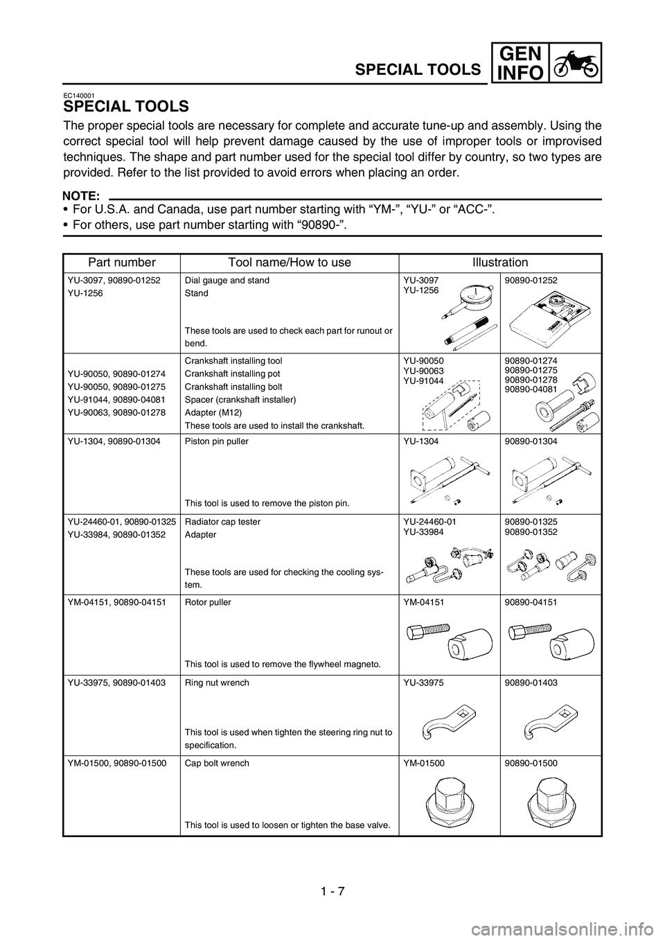
The proper special tools are necessary for complete and accurate tune-up and assembly. Using the
correct special tool will help prevent damage caused by the use of improper tools or improvised
techniques. The shape and part number used for the special tool differ by country, so two types are
provided. Refer to the list provided to avoid errors when placing an order.
NOTE:
For U.S.A. and Canada, use part number starting with “YM-”, “YU-” or “ACC-”.
For others, use part number starting with “90890-”.
Part number Tool name/How to use Illustration
YU-3097, 90890-01252
YU-1256Dial gauge and stand
Stand
These tools are used to check each part for runout or
bend.YU-3097
YU-125690890-01252
YU-90050, 90890-01274
YU-90050, 90890-01275
YU-91044, 90890-04081
YU-90063, 90890-01278Crankshaft installing tool
Crankshaft installing pot
Crankshaft installing bolt
Spacer (crankshaft installer)
Adapter (M12)
These tools are used to install the crankshaft.YU-90050
YU-90063
YU-9104490890-01274
90890-01275
90890-01278
90890-04081
YU-1304, 90890-01304 Piston pin puller
This tool is used to remove the piston pin.YU-1304 90890-01304
YU-24460-01, 90890-01325
YU-33984, 90890-01352Radiator cap tester
Adapter
These tools are used for checking the cooling sys-
tem.YU-24460-01
YU-3398490890-01325
90890-01352
YM-04151, 90890-04151 Rotor puller
This tool is used to remove the flywheel magneto.YM-04151 90890-04151
YU-33975, 90890-01403 Ring nut wrench
This tool is used when tighten the steering ring nut to
specification.YU-33975 90890-01403
YM-01500, 90890-01500 Cap bolt wrench
This tool is used to loosen or tighten the base valve.YM-01500 90890-01500
Page 39 of 650

GEN
INFO
1 - 8
SPECIAL TOOLS
YM-01501, 90890-01501 Cap bolt ring wrench
This tool is used to loosen or tighten the damper
assembly.YM-01501 90890-01501
YM-A0948, 90890-01502 Fork seal driver
This tool is used when install the fork oil seal.YM-A0948 90890-01502
YU-3112-C, 90890-03112 Pocket tester
Use this tool to inspect the coil resistance, output
voltage and amperage.YU-3112-C 90890-03112
YM-33277-A, 90890-03141 Timing light
This tool is necessary for checking ignition timing.YM-33277-A 90890-03141
YM-4019, 90890-04019 Valve spring compressor
This tool is needed to remove and install the valve
assemblies.YM-4019 90890-04019
YM-91042, 90890-04086 Clutch holding tool
This tool is used to hold the clutch when removing or
installing the clutch boss securing nut.YM-91042 90890-04086
YM-4116, 90890-04116
YM-4097, 90890-04097Valve guide remover
Intake 4.5 mm (0.18 in)
Exhaust 5.0 mm (0.20 in)
This tool is needed to remove and install the valve
guide.YM-4116
YM-409790890-04116
90890-04097
YM-4117, 90890-04117
YM-4098, 90890-04098Valve guide installer
Intake
Exhaust
This tool is needed to install the valve guide.YM-4117
YM-409890890-04117
90890-04098
YM-4118, 90890-04118
YM-4099, 90890-04099Valve guide reamer
Intake 4.5 mm (0.18 in)
Exhaust 5.0 mm (0.20 in)
This tool is needed to rebore the new valve guide.YM-4118
YM-4099 90890-04118
90890-04099
Part number Tool name/How to use Illustration
Page 64 of 650

GEN
INFO
1 - 18
TORQUE-CHECK POINTS
TORQUE-CHECK POINTS
NOTE:
Concerning the tightening torque, refer to
“MAINTENANCE SPECIFICATIONS” section
in the CHAPTER 2.
Frame to rear frame
Fuel tank to frame
Silencer to rear frame
Frame to engine
Engine bracket to engine
Engine bracket to frame
Steering shaft to frame
Steering shaft to handle crown
Handle crown to handlebar
Front fork to handle crown
Front fork to under bracket
Assembly of links
Link to frame
Link to shock absorber
Link to swingarm
Shock absorber to frame
Tightening of pivot shaft
Tightening of front axle
Tightening of axle holder
Tightening of rear axle
Wheel to sprocket
Caliper to front fork
Brake disc to wheel
Tightening of union bolt
Master cylinder to handlebar
Tightening of air bleeder
Tightening of brake hose holder
Brake pedal to frame
Brake disc to wheel
Tightening of union bolt
Master cylinder to frame
Tightening of air bleeder
Tightening of brake hose holder
Fuel tank to fuel cock
Tightening of oil hose clamp Frame construction
Combined seat and tank
Exhaust system
Engine mounting
Steering Steering shaft to
handlebar
Suspension Front Steering shaft to front
fork
Rear For link type
Rear Installation of shock
absorber
Rear Installation of
swingarm
Wheel Installation of wheel Front
Rear
Brake Front
Rear
Fuel system
Lubrication system
Page 82 of 650

SPEC
2 - 11 Part to be tightened Thread size Q’tyTightening torque
Nm m·kg ft·lb
Spark plug M10S × 1.0 1 13 1.3 9.4
Camshaft cap M6 × 1.0 10 10 1.0 7.2
Cylinder head blind plug screw M12 × 1.0 1 28 2.8 20
Cylinder head (stud bolt) M8 × 1.25 1 15 1.5 11
(bolt) M10 × 1.25 4 Refer to NOTE.*
1
(bolt) M6 × 1.0 2 10 1.0 7.2
Cylinder head cover M6 × 1.0 2 10 1.0 7.2
Cylinder M6 × 1.0 1 10 1.0 7.2
Timing chain tensioner M6 × 1.0 2 10 1.0 7.2
Tensioner cap bolt M6 × 1.0 1 7 0.7 5.1
Timing chain guide (rear) M6 × 1.0 2 10 1.0 7.2
Exhaust pipe (nut) M8 × 1.25 1 13 1.3 9.4
(bolt) M8 × 1.25 1 24 2.4 17
Silencer M8 × 1.25 2 35 3.5 25
Silencer clamp M8 × 1.25 1 16 1.6 11
Exhaust pipe protector M6 × 1.0 3 10 1.0 7.2
Carburetor joint M6 × 1.0 3 10 1.0 7.2
Carburetor joint clamp M4 × 0.7 1 3 0.3 2.2
Air filter case M6 × 1.0 2 8 0.8 5.8
Air filter joint clamp M6 × 1.0 1 3 0.3 2.2
Air filter joint and air filter case M5 × 0.8 1 4 0.4 2.9
Throttle cable adjust bolt and locknut M6 × 0.75 1 4 0.4 2.9
Throttle cable (pull) M6 × 1.0 1 4 0.4 2.9
Throttle cable (return) M12 × 1.0 1 11 1.1 8.0
Throttle cable cover M5 × 0.8 2 4 0.4 2.9
Hot starter plunger M12 × 1.0 1 2 0.2 1.4
Hot starter cable adjust bolt and locknut M6 × 0.75 1 4 0.4 2.9
Air filter element M6 × 1.0 1 2 0.2 1.4
Radiator panel (upper) M6 × 1.0 2 10 1.0 7.2
Radiator M6 × 1.0 4 10 1.0 7.2
Radiator hose clamp M6 × 1.0 8 2 0.2 1.4
Radiator pipe 1, 2 M6 × 1.0 2 10 1.0 7.2
Impeller M8 × 1.25 1 14 1.4 10
Water pump housing cover M6 × 1.0 3 10 1.0 7.2
Coolant drain bolt M6 × 1.0 1 10 1.0 7.2
Oil pump cover M4 × 0.7 1 2 0.2 1.4
Oil pump M6 × 1.0 2 10 1.0 7.2
Engine oil drain bolt (oil filter) M6 × 1.0 1 10 1.0 7.2
Oil filter cover M6 × 1.0 2 10 1.0 7.2
Oil check bolt (cylinder head) M6 × 1.0 1 10 1.0 7.2
Oil hose clamp—220.21.4
Clutch cover M6 × 1.0 7 10 1.0 7.2
MAINTENANCE SPECIFICATIONS
Page 83 of 650
SPEC
2 - 12
NOTE:
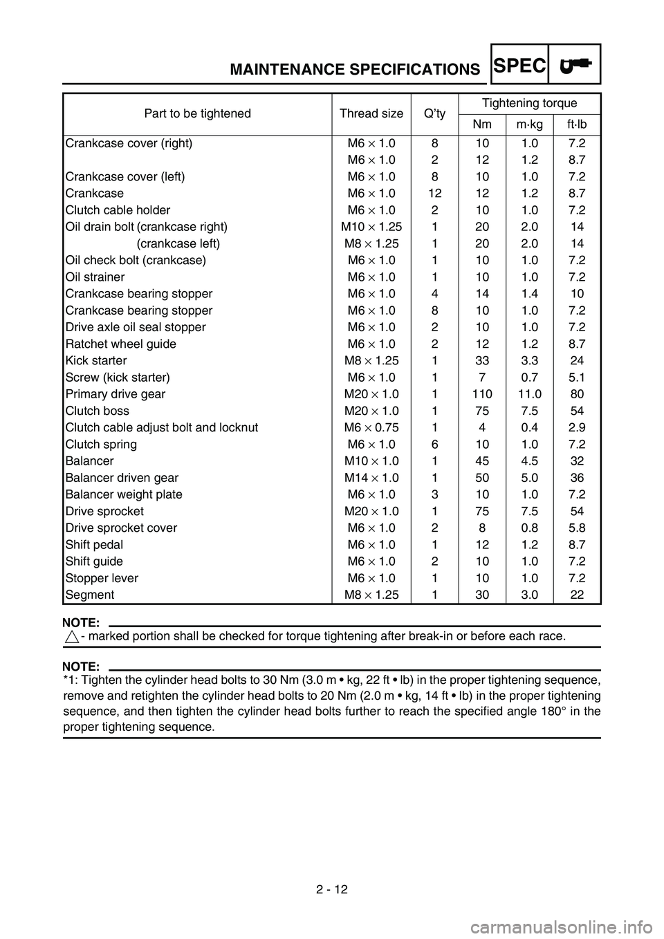
- marked portion shall be checked for torque tightening after break-in or before each race.
NOTE:
*1: Tighten the cylinder head bolts to 30 Nm (3.0 m kg, 22 ft lb) in the proper tightening sequence,
remove and retighten the cylinder head bolts to 20 Nm (2.0 m kg, 14 ft lb) in the proper tightening
sequence, and then tighten the cylinder head bolts further to reach the specified angle 180° in the
proper tightening sequence.Crankcase cover (right) M6 × 1.0 8 10 1.0 7.2
M6 × 1.0 2 12 1.2 8.7
Crankcase cover (left) M6 × 1.0 8 10 1.0 7.2
Crankcase M6 × 1.0 12 12 1.2 8.7
Clutch cable holder M6 × 1.0 2 10 1.0 7.2
Oil drain bolt (crankcase right) M10 × 1.25 1 20 2.0 14
(crankcase left) M8 × 1.25 1 20 2.0 14
Oil check bolt (crankcase) M6 × 1.0 1 10 1.0 7.2
Oil strainer M6 × 1.0 1 10 1.0 7.2
Crankcase bearing stopper M6 × 1.0 4 14 1.4 10
Crankcase bearing stopper M6 × 1.0 8 10 1.0 7.2
Drive axle oil seal stopper M6 × 1.0 2 10 1.0 7.2
Ratchet wheel guide M6 × 1.0 2 12 1.2 8.7
Kick starter M8 × 1.25 1 33 3.3 24
Screw (kick starter) M6 × 1.0 1 7 0.7 5.1
Primary drive gear M20 × 1.0 1 110 11.0 80
Clutch boss M20 × 1.0 1 75 7.5 54
Clutch cable adjust bolt and locknut M6 × 0.75 1 4 0.4 2.9
Clutch spring M6 × 1.0 6 10 1.0 7.2
Balancer M10 × 1.0 1 45 4.5 32
Balancer driven gear M14 × 1.0 1 50 5.0 36
Balancer weight plate M6 × 1.0 3 10 1.0 7.2
Drive sprocket M20 × 1.0 1 75 7.5 54
Drive sprocket cover M6 × 1.0 2 8 0.8 5.8
Shift pedal M6 × 1.0 1 12 1.2 8.7
Shift guide M6 × 1.0 2 10 1.0 7.2
Stopper lever M6 × 1.0 1 10 1.0 7.2
Segment M8 × 1.25 1 30 3.0 22 Part to be tightened Thread size Q’tyTightening torque
Nm m·kg ft·lb
MAINTENANCE SPECIFICATIONS
Page 86 of 650

SPEC
2 - 15
NOTE:
1. First, tighten the ring nut approximately 38 Nm (3.8 m kg, 27 ft lb) by using the ring nut wrench,
then loosen the ring nut one turn.
2. Retighten the ring nut 7 Nm (0.7 m kg, 5.1 ft lb). Part to be tightened Thread size Q’tyTightening torque
Nm m·kg ft·lb
Handle crown and outer tube M8 × 1.25 4 23 2.3 17
Under bracket and outer tube M8 × 1.25 4 20 2.0 14
Handle crown and steering shaft M24 × 1.0 1 145 14.5 105
Handlebar holder (upper) M8 × 1.25 4 28 2.8 20
Handlebar holder (lower) M12 × 1.25 2 40 4.0 29
Steering ring nut M28 × 1.0 1 Refer to NOTE.
Front fork and damper assembly M51 × 1.5 2 30 3.0 22
Front fork and adjuster M22 × 1.25 2 55 5.5 40
Damper assembly and base valve M42 × 1.5 2 29 2.9 21
Adjuster and damper assembly M12 × 1.25 2 29 2.9 21
Bleed screw (front fork) and base valve M5 × 0.8 2 1 0.1 0.7
Front fork and protector M6 × 1.0 6 7 0.7 5.1
Protector and brake hose holder M6 × 1.0 2 7 0.7 5.1
Throttle cable cap M5 × 0.8 2 4 0.4 2.9
Clutch lever holder mounting M5 × 0.8 2 4 0.4 2.9
Clutch lever mounting (nut) M6 × 1.0 1 4 0.4 2.9
Hot starter lever holder mounting M5 × 0.8 2 4 0.4 2.9
Front brake master cylinder and bracket M6 × 1.0 2 9 0.9 6.5
Front brake master cylinder cap M4 × 0.7 2 2 0.2 1.4
Brake lever mounting (bolt) M6 × 1.0 1 6 0.6 4.3
Brake lever mounting (nut) M6 × 1.0 1 6 0.6 4.3
Brake lever position locknut M6 × 1.0 1 5 0.5 3.6
Cable guide (front brake hose) and under bracket M6 × 1.0 1 4 0.4 2.9
Front brake hose union bolt (master cylinder) M10 × 1.25 1 30 3.0 22
Front brake hose union bolt (caliper) M10 × 1.25 1 30 3.0 22
Front brake caliper and front fork M8 × 1.25 2 23 2.3 17
Front brake caliper and brake hose holder M6 × 1.0 1 10 1.0 7.2
Brake caliper (front and rear) and pad pin plug M10 × 1.0 2 3 0.3 2.2
Brake caliper (front and rear) and pad pin M10 × 1.0 2 18 1.8 13
Brake caliper (front and rear) and bleed screw M8 × 1.25 2 6 0.6 4.3
Front wheel axle and nut M16 × 1.5 1 105 10.5 75
Front wheel axle holder M8 × 1.25 4 23 2.3 17
Front brake disc and wheel hub M6 × 1.0 6 12 1.2 8.7
Rear brake disc and wheel hub M6 × 1.0 6 14 1.4 10
Footrest bracket and frame M10 × 1.25 4 55 5.5 40
Brake pedal mounting M8 × 1.25 1 26 2.6 19
Rear brake master cylinder and frame M6 × 1.0 2 10 1.0 7.2
Rear brake master cylinder cap M4 × 0.7 2 2 0.2 1.4
Rear brake hose union bolt (caliper) M10 × 1.25 1 30 3.0 22
Rear brake hose union bolt (master cylinder) M10 × 1.25 1 30 3.0 22
MAINTENANCE SPECIFICATIONS
Page 87 of 650

SPEC
2 - 16
NOTE:
- marked portion shall be checked for torque tightening after break-in or before each race.Part to be tightened Thread size Q’tyTightening torque
Nm m·kg ft·lb
Rear wheel axle and nut M20 × 1.5 1 125 12.5 90
Driven sprocket and wheel hub M8 × 1.25 6 42 4.2 30
Nipple (spoke)—72 3 0.3 2.2
Disc cover and rear brake caliper M6 × 1.0 2 10 1.0 7.2
Protector and rear brake caliper M6 × 1.0 2 7 0.7 5.1
Chain puller adjust bolt and locknut M8 × 1.25 2 16 1.6 11
Engine mounting:
Engine upper bracket and frame M10 × 1.25 4 55 5.5 40
Engine lower bracket and frame M8 × 1.25 4 34 3.4 24
Engine and engine bracket (front) M10 × 1.25 1 53 5.3 38
Engine and engine bracket (upper) M10 × 1.25 1 55 5.5 40
Engine and frame (lower) M10 × 1.25 1 53 5.3 38
Engine guard M6 × 1.0 1 10 1.0 7.2
Engine skid plate mounting M6 × 1.0 3 10 1.0 7.2
CDI unit bracket mounting M6 × 1.0 2 7 0.7 5.1
Cable guide and CDI unit bracket M5 × 0.8 2 4 0.4 2.9
Cable guide and frame M5 × 0.8 1 5 0.5 3.6
Pivot shaft and nut M16 × 1.5 1 85 8.5 61
Relay arm and swingarm M14 × 1.5 1 70 7.0 50
Relay arm and connecting rod M14 × 1.5 1 80 8.0 58
Connecting rod and frame M14 × 1.5 1 80 8.0 58
Rear shock absorber and frame M10 × 1.25 1 56 5.6 40
Rear shock absorber and relay arm M10 × 1.25 1 53 5.3 38
Rear frame and frame (upper) M8 × 1.25 1 32 3.2 23
Rear frame and frame (lower) M8 × 1.25 2 32 3.2 23
Swingarm and brake hose holder M5 × 0.8 4 2 0.2 1.4
Swingarm and patch M4 × 0.7 4 2 0.2 1.4
Drive chain tensioner mounting (upper) M8 × 1.25 1 16 1.6 11
Drive chain tensioner mounting (lower) M8 × 1.25 1 16 1.6 11
Chain support and swingarm M6 × 1.0 3 7 0.7 5.1
Seal guard and swingarm M5 × 0.8 4 6 0.6 4.3
Fuel tank mounting boss and frame M10 × 1.25 1 20 2.0 14
Fuel tank mounting M6 × 1.0 2 10 1.0 7.2
Fuel tank and fuel cock M6 × 1.0 2 6 0.6 4.3
Fuel tank and seat set bracket M6 × 1.0 1 7 0.7 5.1
Fuel tank and fuel tank bracket M6 × 1.0 4 7 0.7 5.1
Seat mounting M8 × 1.25 2 23 2.3 17
Side cover mounting M6 × 1.0 2 7 0.7 5.1
Air scoop and fuel tank M6 × 1.0 6 7 0.7 5.1
Air scoop and radiator panel (lower) M6 × 1.0 2 7 0.7 5.1
Front fender mounting M6 × 1.0 4 7 0.7 5.1
Rear fender mounting (front) M6 × 1.0 2 7 0.7 5.1
Rear fender mounting (rear) M6 × 1.0 2 16 1.6 11
Number plate M6 × 1.0 1 7 0.7 5.1
MAINTENANCE SPECIFICATIONS
Page 89 of 650

SPEC
2 - 18
EC220001
GENERAL TORQUE SPECIFICATIONS
This chart specifies torque for standard fasten-
ers with standard I.S.O. pitch threads. Torque
specifications for special components or
assemblies are included in the applicable sec-
tions of this book. To avoid warpage, tighten
multi-fastener assemblies in a crisscross fash-
ion, in progressive stages, until full torque is
reached. Unless otherwise specified, torque
specifications call for clean, dry threads. Com-
ponents should be at room temperature.
A: Distance between flats
B: Outside thread diameter
EC230000
DEFINITION OF UNITS
A
(Nut)B
(Bolt)TORQUE
SPECIFICATION
Nm mkg ftlb
10 mm
12 mm
14 mm
17 mm
19 mm
22 mm6 mm
8 mm
10 mm
12 mm
14 mm
16 mm6
15
30
55
85
1300.6
1.5
3.0
5.5
8.5
134.3
11
22
40
61
94
Unit Read Definition Measure
mm
cmmillimeter
centimeter10
-3 meter
10-2 meterLength
Length
kg kilogram 10
3 gram Weight
N Newton 1 kg
× m/sec
2 Force
Nm
m kgNewton meter
Meter kilogramN
× m
m
× kgTorque
Torque
Pa Pascal N/m
2Pressure
N/mm Newton per millimeter N/mm Spring rate
L
cm
3 Liter
Cubic centimeter—
—Volume or capacity
Volume or capacity
r/min Revolution per minute—Engine speed
GENERAL TORQUE SPECIFICATIONS/
DEFINITION OF UNITS