start stop button YAMAHA YZ450F 2006 Owners Manual
[x] Cancel search | Manufacturer: YAMAHA, Model Year: 2006, Model line: YZ450F, Model: YAMAHA YZ450F 2006Pages: 650, PDF Size: 20.71 MB
Page 26 of 650

GEN
INFO
1 - 1
DESCRIPTION
EC100000
GENERAL INFORMATION
EC110000
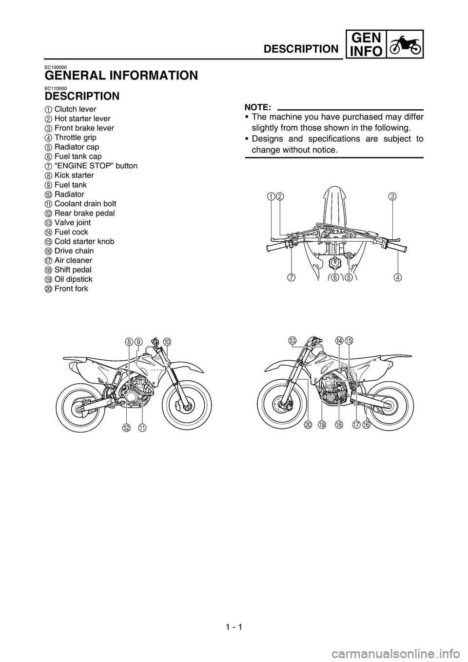
DESCRIPTION
1Clutch lever
2Hot starter lever
3Front brake lever
4Throttle grip
5Radiator cap
6Fuel tank cap
7“ENGINE STOP” button
8Kick starter
9Fuel tank
0Radiator
ACoolant drain bolt
BRear brake pedal
CValve joint
DFuel cock
ECold starter knob
FDrive chain
GAir cleaner
HShift pedal
IOil dipstick
JFront forkNOTE:
The machine you have purchased may differ
slightly from those shown in the following.
Designs and specifications are subject to
change without notice.
Page 48 of 650

1 - 10
GEN
INFO
CONTROL FUNCTIONS
EC150000
CONTROL FUNCTIONS
EC151000
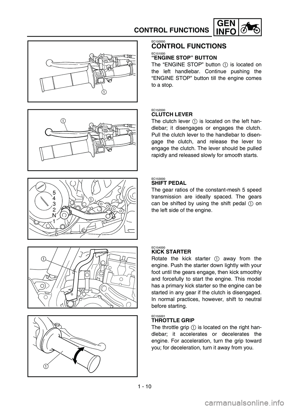
“ENGINE STOP” BUTTON
The “ENGINE STOP” button 1 is located on
the left handlebar. Continue pushing the
“ENGINE STOP” button till the engine comes
to a stop.
EC152000
CLUTCH LEVER
The clutch lever 1 is located on the left han-
dlebar; it disengages or engages the clutch.
Pull the clutch lever to the handlebar to disen-
gage the clutch, and release the lever to
engage the clutch. The lever should be pulled
rapidly and released slowly for smooth starts.
EC153000
SHIFT PEDAL
The gear ratios of the constant-mesh 5 speed
transmission are ideally spaced. The gears
can be shifted by using the shift pedal 1 on
the left side of the engine.
EC154000
KICK STARTER
Rotate the kick starter 1 away from the
engine. Push the starter down lightly with your
foot until the gears engage, then kick smoothly
and forcefully to start the engine. This model
has a primary kick starter so the engine can be
started in any gear if the clutch is disengaged.
In normal practices, however, shift to neutral
before starting.
1
EC155001
THROTTLE GRIP
The throttle grip 1 is located on the right han-
dlebar; it accelerates or decelerates the
engine. For acceleration, turn the grip toward
you; for deceleration, turn it away from you.
Page 62 of 650

1 - 17
GEN
INFO
BREAK-IN PROCEDURES
1. Before starting the engine, fill the fuel tank
with the fuel.
2. Perform the pre-operation checks on the
machine.
3. Start and warm up the engine. Check the
idle speed, and check the operation of the
controls and the “ENGINE STOP” button.
Then, restart the engine and check its
operation within no more than 5 minutes
after it is restarted.
4. Operate the machine in the lower gears at
moderate throttle openings for five to eight
minutes.
5. Check how the engine runs when the
machine is ridden with the throttle 1/4 to 1/2
open (low to medium speed) for about one
hour.
6. Restart the engine and check the operation
of the machine throughout its entire operat-
ing range. Restart the machine and oper-
ate it for about 10 to 15 more minutes. The
machine will now be ready to race.
CAUTION:
After the break-in or before each race,
you must check the entire machine for
loose fittings and fasteners as per
“TORQUE-CHECK POINTS”.
Tighten all such fasteners as required.
When any of the following parts have
been replaced, they must be broken in.
CYLINDER AND CRANKSHAFT:
About one hour of break-in operation is
necessary.
PISTON, RING, VALVES, CAMSHAFTS
AND GEARS:
These parts require about 30 minutes of
break-in operation at half-throttle or less.
Observe the condition of the engine care-
fully during operation.
STARTING AND BREAK-IN
Page 132 of 650

2 - 22
SPECCABLE ROUTING DIAGRAM
1Hot starter cable
2Clamp
3TPS (throttle position sensor)
lead
4Hump (frame)
5Neutral switch lead
6Engine bracket
7Engine skid plate stay
8CDI magneto lead
9Clutch cable
0Radiator breather hose
ARadiator hose 2
B“ENGINE STOP” button leadCSub wire harness
DGround lead
ECDI unit bracket
FCDI unit
GCable guide
HIgnition coil lead
IThrottle cable
ÈFasten the hot starter cable and
throttle cables onto the frame.
Locate the clamp ends under
the hot starter cable.ÉFasten the hot starter cable,
throttle cables, TPS lead and
ignition coil lead to the frame.
ÊFasten the TPS lead to the
frame behind its hump.
ËPass the TPS lead over the hot
starter cable.
ÌPass the neutral switch lead on
the inside of the engine bracket.
ÍPass the neutral switch lead
over the engine skid plate stay.
C-C
G-G
E
2
Õ
4 58E
É
D GGA
AB
D
5
ÌÍ Í
Í Î
F
E
D
2
2
2
Ï Ð Ò
Ñ Ó
1
G
2
3
4 2
0
8
5
9
8Ë Ê
0
0 8 5
CC
B
È 2
9
FF
Ô
Ô
B-B
A-A
I
H
3
1
C
B
A
0
0
8
5
D-D
3 F-F
6
7
2 5 0
Page 140 of 650

2 - 26
SPECCABLE ROUTING DIAGRAM
1Throttle cable
2Clamp
3Hot starter cable
4Clutch cable
5“ENGINE STOP” button lead
6Cable guide
7Brake hose
8Hose guideÈFasten the “ENGINE STOP” button lead to the
handlebar.
ÉPass the clutch cable and hot starter cable
through the cable guide.
ÊPass the brake hose in front of the number plate.
ËPass the throttle cables through the cable guide.
ÌPass the clutch cable and hot starter cable
through the cable guide on the number plate.
A
B
C
A
B
C40˚± 10˚
40˚± 10˚
2
È3
2
5
4
2
3
5
6
Ë1
4
5
7
Ê
6
É
Ì
8
Page 524 of 650

5 - 43
CHAS
EC5B0000
HANDLEBAR
Extent of removal:
1 Handlebar removal
Extent of removal Order Part name Q’ty Remarks
HANDLEBAR REMOVAL
Preparation for removal Number plate Remove the band only.
1 Hot starter cable 1 Disconnect at the lever side.
2 Hot starter lever holder 1
3 Clutch cable 1 Disconnect at the lever side.
4 Clutch lever holder 1
5“ENGINE STOP” button 1
6 Master cylinder 1 Refer to “REMOVAL POINTS”.
7 Throttle cable cap 1
8 Throttle cable #1 (pulled) 1 Disconnect at the throttle side.
9 Throttle cable #2 (pushed) 1 Disconnect at the throttle side.
10 Grip (right) 1 Refer to “REMOVAL POINTS”.
11 Tube guide 1
12 Collar 1
13 Grip (left) 1 Refer to “REMOVAL POINTS”.
14 Handlebar holder (upper) 2
15 Handlebar 1
16 Handlebar holder (lower) 2
1
HANDLEBAR
Page 534 of 650

5 - 48
CHASHANDLEBAR
11. Install:
•“ENGINE STOP” button 1
•Clutch lever holder 2
•Bolt (clutch lever holder) 3
•Hot starter lever holder 4
•Bolt (hot starter lever holder) 5
•Clamp 6
NOTE:
•The “ENGINE STOP” button, clutch lever
holder and clamp should be installed accord-
ing to the dimensions shown.
•Pass the “ENGINE STOP” button lead in the
middle of the clutch lever holder.
T R..4 Nm (0.4 m · kg, 2.9 ft · lb)
T R..4 Nm (0.4 m · kg, 2.9 ft · lb)
12. Install:
•Clutch cable 1
•Hot starter cable 2
NOTE:
Apply the lithium soap base grease on the
clutch cable end and hot starter cable end.
13. Adjust:
•Clutch lever free play
Refer to “CLUTCH ADJUSTMENT” sec-
tion in the CHAPTER 3.
•Hot starter lever free play
Refer to “HOT STARTER LEVER
ADJUSTMENT” section in the CHAPTER
3.
Page 584 of 650

6 - 4
–+ELECIGNITION SYSTEM
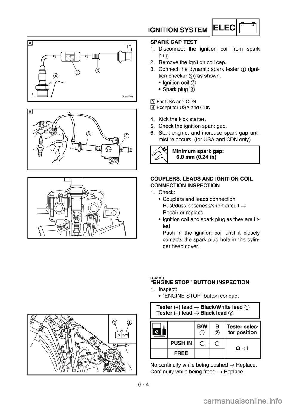
SPARK GAP TEST
1. Disconnect the ignition coil from spark
plug.
2. Remove the ignition coil cap.
3. Connect the dynamic spark tester 1 (igni-
tion checker 2) as shown.
•Ignition coil 3
•Spark plug 4
ÈFor USA and CDN
ÉExcept for USA and CDN
4. Kick the kick starter.
5. Check the ignition spark gap.
6. Start engine, and increase spark gap until
misfire occurs. (for USA and CDN only)
Minimum spark gap:
6.0 mm (0.24 in)
È
É
COUPLERS, LEADS AND IGNITION COIL
CONNECTION INSPECTION
1. Check:
•Couplers and leads connection
Rust/dust/looseness/short-circuit →
Repair or replace.
•Ignition coil and spark plug as they are fit-
ted
Push in the ignition coil until it closely
contacts the spark plug hole in the cylin-
der head cover.
EC625001
“ENGINE STOP” BUTTON INSPECTION
1. Inspect:
•“ENGINE STOP” button conduct
No continuity while being pushed → Replace.
Continuity while being freed → Replace. Tester (+) lead
→ Black/White lead
1
Tester (–) lead
→ Black lead
2
B/W
1 B
2 Tester selec-
tor position
PUSH IN
Ω
× 1
FREE1 2
B/W B