clutch YAMAHA YZ450F 2007 Notices Demploi (in French)
[x] Cancel search | Manufacturer: YAMAHA, Model Year: 2007, Model line: YZ450F, Model: YAMAHA YZ450F 2007Pages: 650, PDF Size: 20.67 MB
Page 244 of 650
4 - 2
ENG
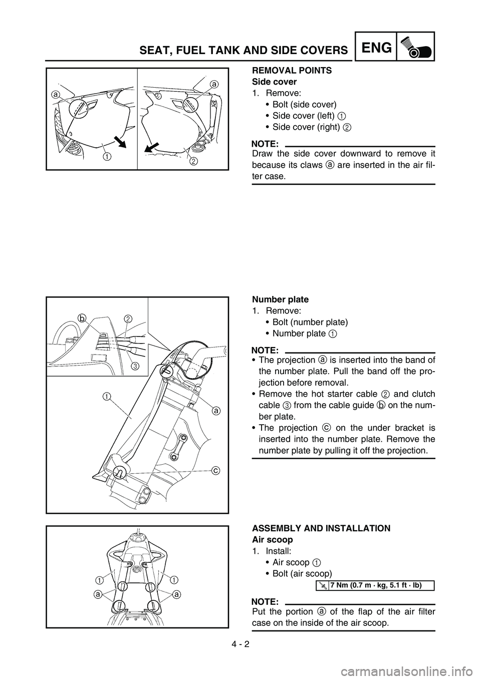
REMOVAL POINTS
Side cover
1. Remove:
Bolt (side cover)
Side cover (left) 1
Side cover (right) 2
NOTE:
Draw the side cover downward to remove it
because its claws a are inserted in the air fil-
ter case.
Number plate
1. Remove:
Bolt (number plate)
Number plate 1
NOTE:
The projection a is inserted into the band of
the number plate. Pull the band off the pro-
jection before removal.
Remove the hot starter cable 2 and clutch
cable 3 from the cable guide b on the num-
ber plate.
The projection c on the under bracket is
inserted into the number plate. Remove the
number plate by pulling it off the projection.
ASSEMBLY AND INSTALLATION
Air scoop
1. Install:
Air scoop 1
Bolt (air scoop)
NOTE:
Put the portion a of the flap of the air filter
case on the inside of the air scoop.
T R..7 Nm (0.7 m · kg, 5.1 ft · lb)
SEAT, FUEL TANK AND SIDE COVERS
Page 338 of 650
4 - 49
ENGCLUTCH
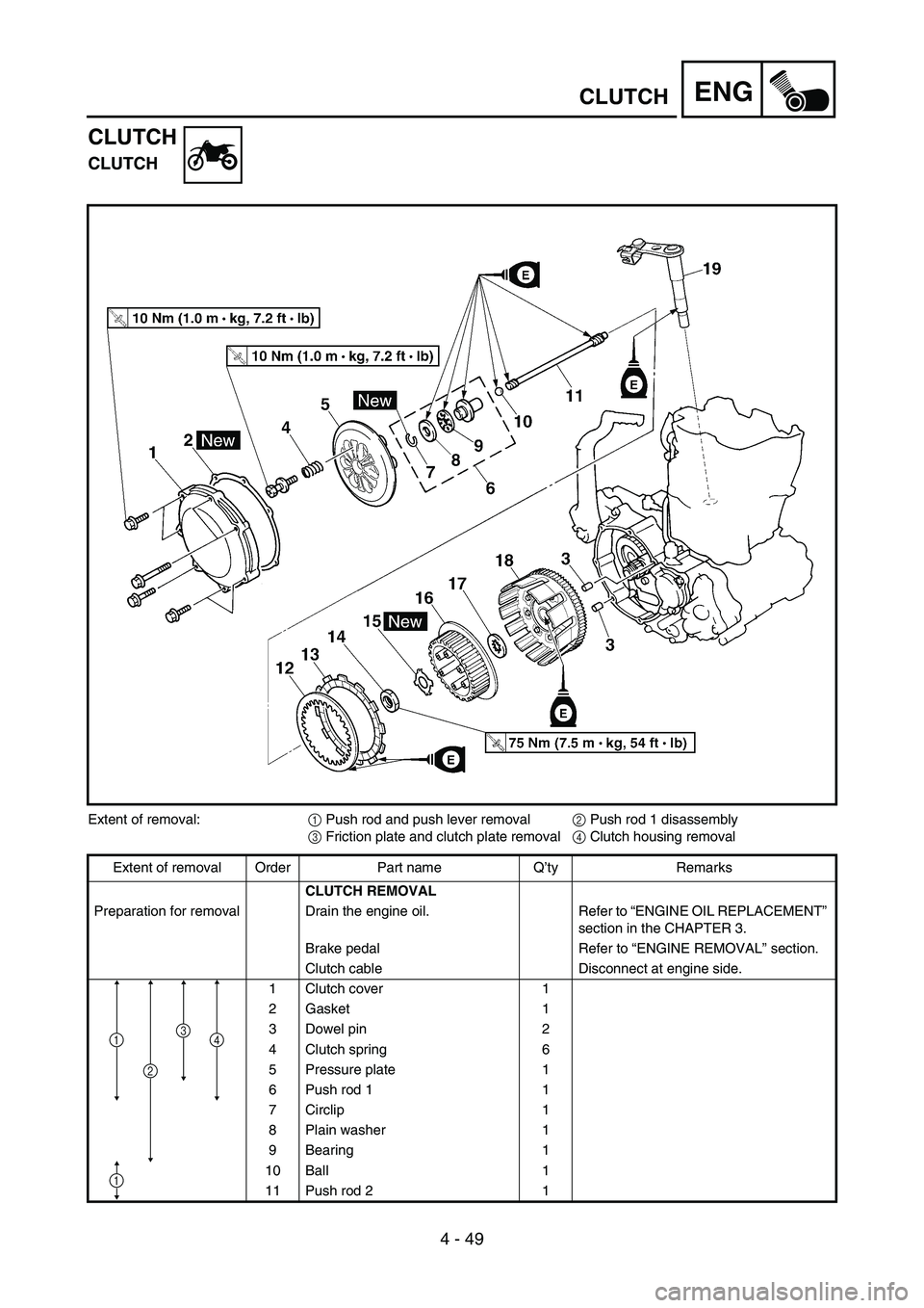
CLUTCH
CLUTCH
Extent of removal:
1 Push rod and push lever removal
2 Push rod 1 disassembly
3 Friction plate and clutch plate removal
4 Clutch housing removal
Extent of removal Order Part name Q’ty Remarks
CLUTCH REMOVAL
Preparation for removal Drain the engine oil. Refer to “ENGINE OIL REPLACEMENT”
section in the CHAPTER 3.
Brake pedal Refer to “ENGINE REMOVAL” section.
Clutch cable Disconnect at engine side.
1 Clutch cover 1
2 Gasket 1
3 Dowel pin 2
4 Clutch spring 6
5 Pressure plate 1
6 Push rod 1 1
7 Circlip 1
8 Plain washer 1
9 Bearing 1
10 Ball 1
11 Push rod 2 1
41
2
3
1
Page 340 of 650
4 - 50
ENGCLUTCH
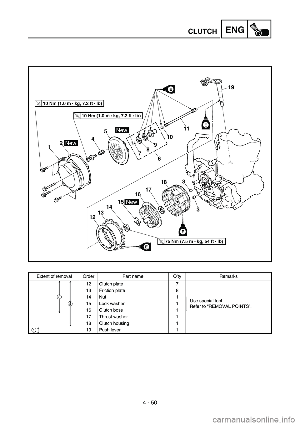
Extent of removal Order Part name Q’ty Remarks
12 Clutch plate 7
13 Friction plate 8
14 Nut 1
Use special tool.
Refer to “REMOVAL POINTS”. 15 Lock washer 1
16 Clutch boss 1
17 Thrust washer 1
18 Clutch housing 1
19 Push lever 1
4
1
3
Page 342 of 650
4 - 51
ENGCLUTCH
EC493000
REMOVAL POINTS
EC483211
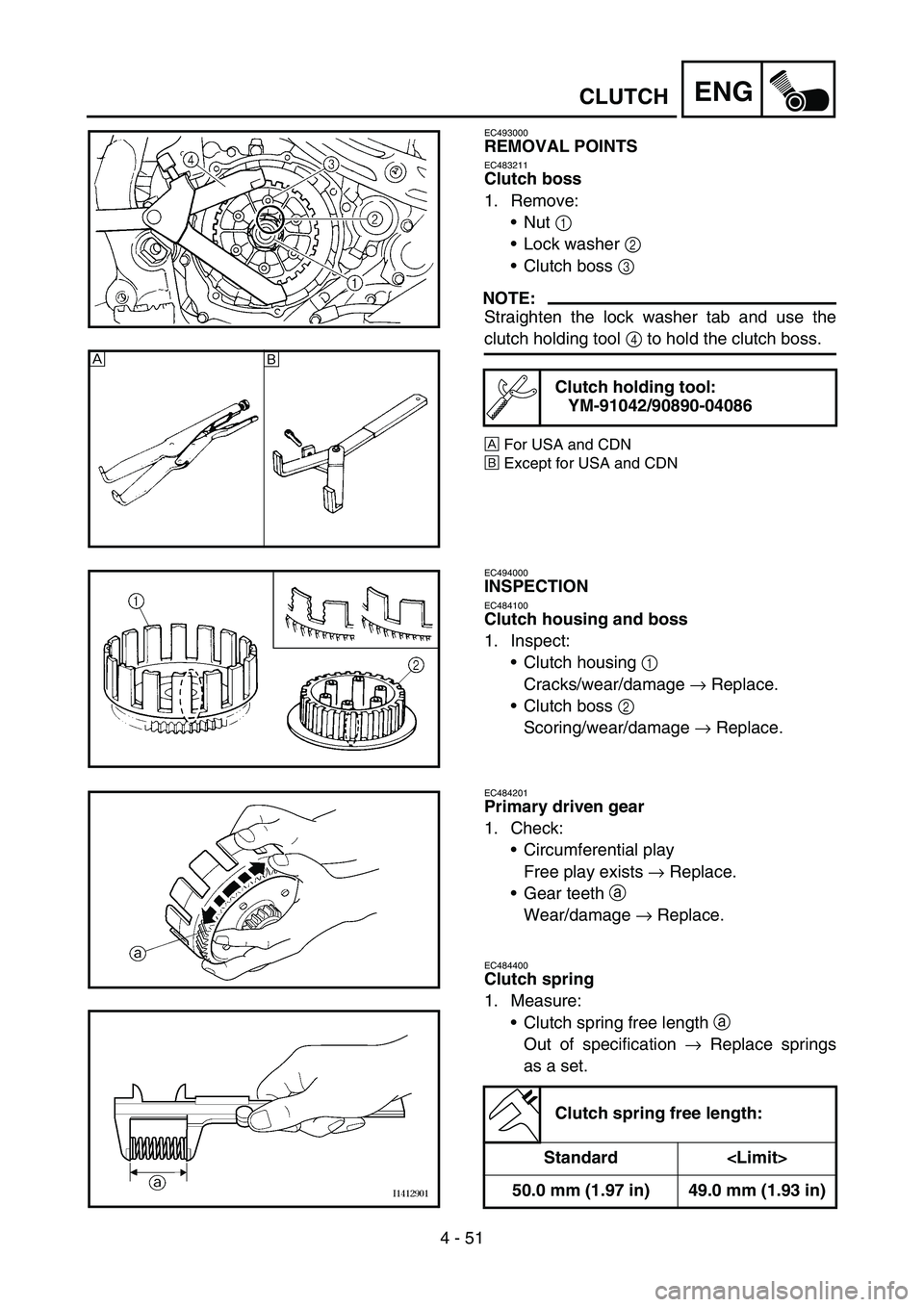
Clutch boss
1. Remove:
Nut 1
Lock washer 2
Clutch boss 3
NOTE:
Straighten the lock washer tab and use the
clutch holding tool 4 to hold the clutch boss.
ÈFor USA and CDN
ÉExcept for USA and CDN
Clutch holding tool:
YM-91042/90890-04086
È
É
EC494000
INSPECTION
EC484100
Clutch housing and boss
1. Inspect:
Clutch housing 1
Cracks/wear/damage → Replace.
Clutch boss 2
Scoring/wear/damage → Replace.
EC484201
Primary driven gear
1. Check:
Circumferential play
Free play exists → Replace.
Gear teeth
a
Wear/damage → Replace.
EC484400
Clutch spring
1. Measure:
Clutch spring free length
a
Out of specification → Replace springs
as a set.
Clutch spring free length:
Standard
50.0 mm (1.97 in) 49.0 mm (1.93 in)
Page 344 of 650
4 - 52
ENGCLUTCH
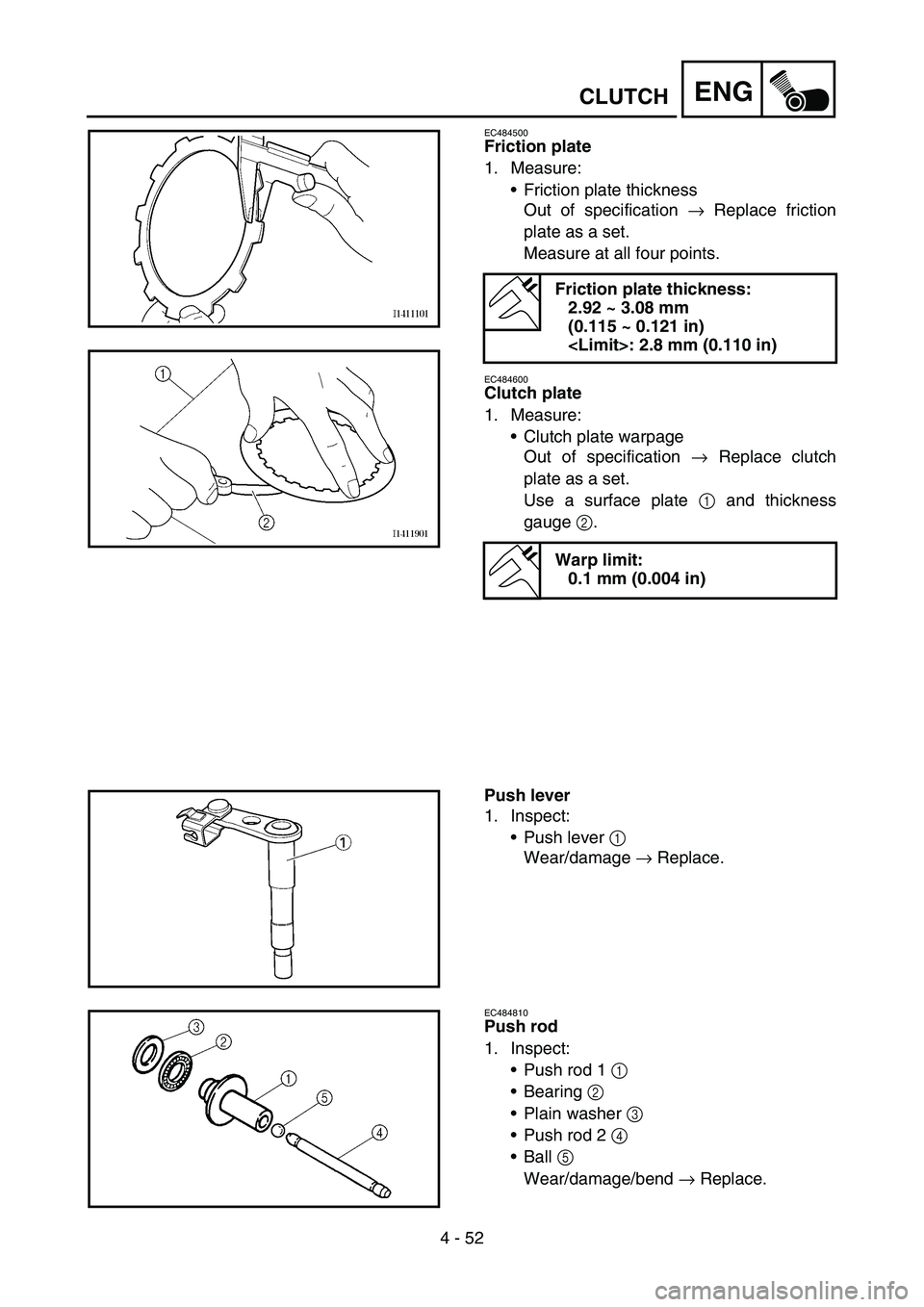
EC484500
Friction plate
1. Measure:
Friction plate thickness
Out of specification → Replace friction
plate as a set.
Measure at all four points.
EC484600
Clutch plate
1. Measure:
Clutch plate warpage
Out of specification → Replace clutch
plate as a set.
Use a surface plate 1 and thickness
gauge 2.
Friction plate thickness:
2.92 ~ 3.08 mm
(0.115 ~ 0.121 in)
Warp limit:
0.1 mm (0.004 in)
Push lever
1. Inspect:
Push lever 1
Wear/damage → Replace.
EC484810
Push rod
1. Inspect:
Push rod 1 1
Bearing 2
Plain washer 3
Push rod 2 4
Ball 5
Wear/damage/bend → Replace.
Page 346 of 650
4 - 53
ENGCLUTCH
EC4A5000
ASSEMBLY AND INSTALLATION
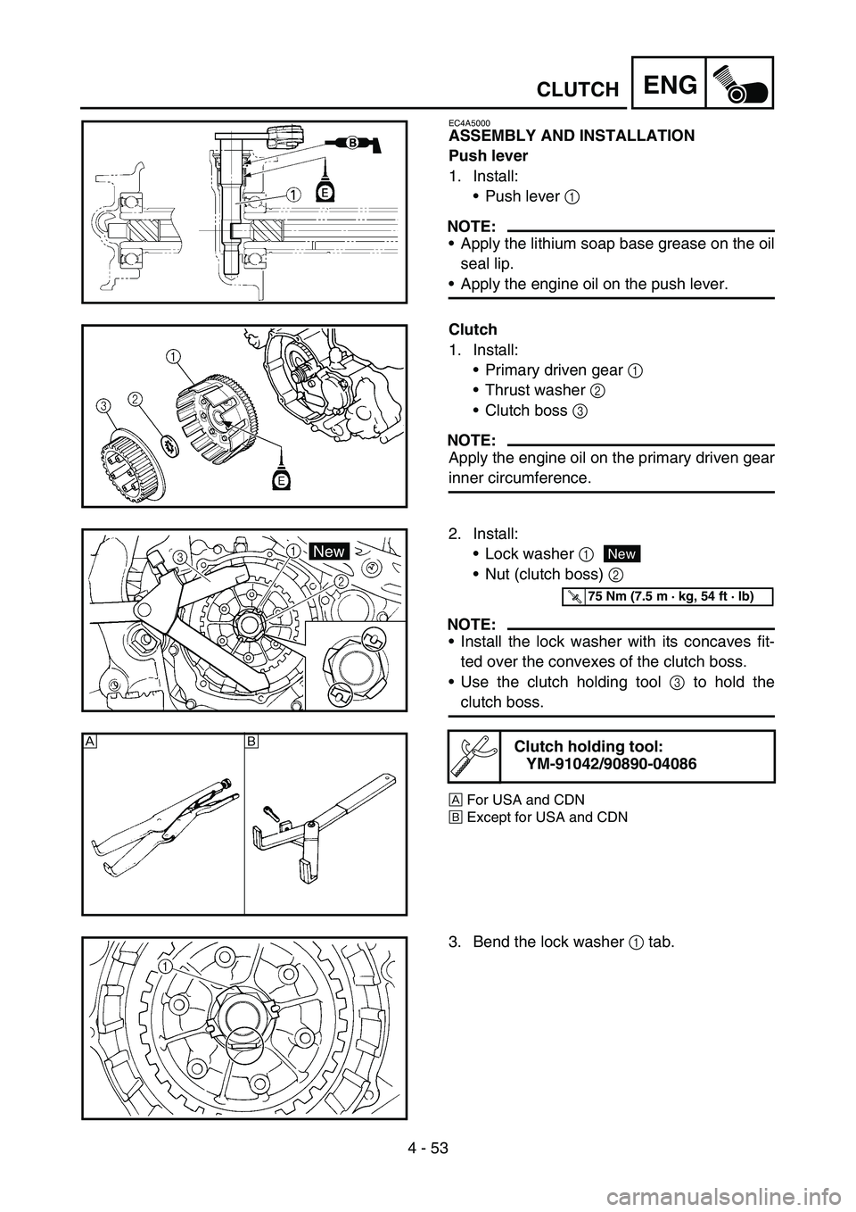
Push lever
1. Install:
Push lever 1
NOTE:
Apply the lithium soap base grease on the oil
seal lip.
Apply the engine oil on the push lever.
Clutch
1. Install:
Primary driven gear 1
Thrust washer 2
Clutch boss 3
NOTE:
Apply the engine oil on the primary driven gear
inner circumference.
2. Install:
Lock washer 1
Nut (clutch boss) 2
NOTE:
Install the lock washer with its concaves fit-
ted over the convexes of the clutch boss.
Use the clutch holding tool 3 to hold the
clutch boss.
ÈFor USA and CDN
ÉExcept for USA and CDN
Clutch holding tool:
YM-91042/90890-04086
New
T R..75 Nm (7.5 m · kg, 54 ft · lb)
ÈÉ
3. Bend the lock washer 1 tab.
Page 348 of 650
4 - 54
ENGCLUTCH
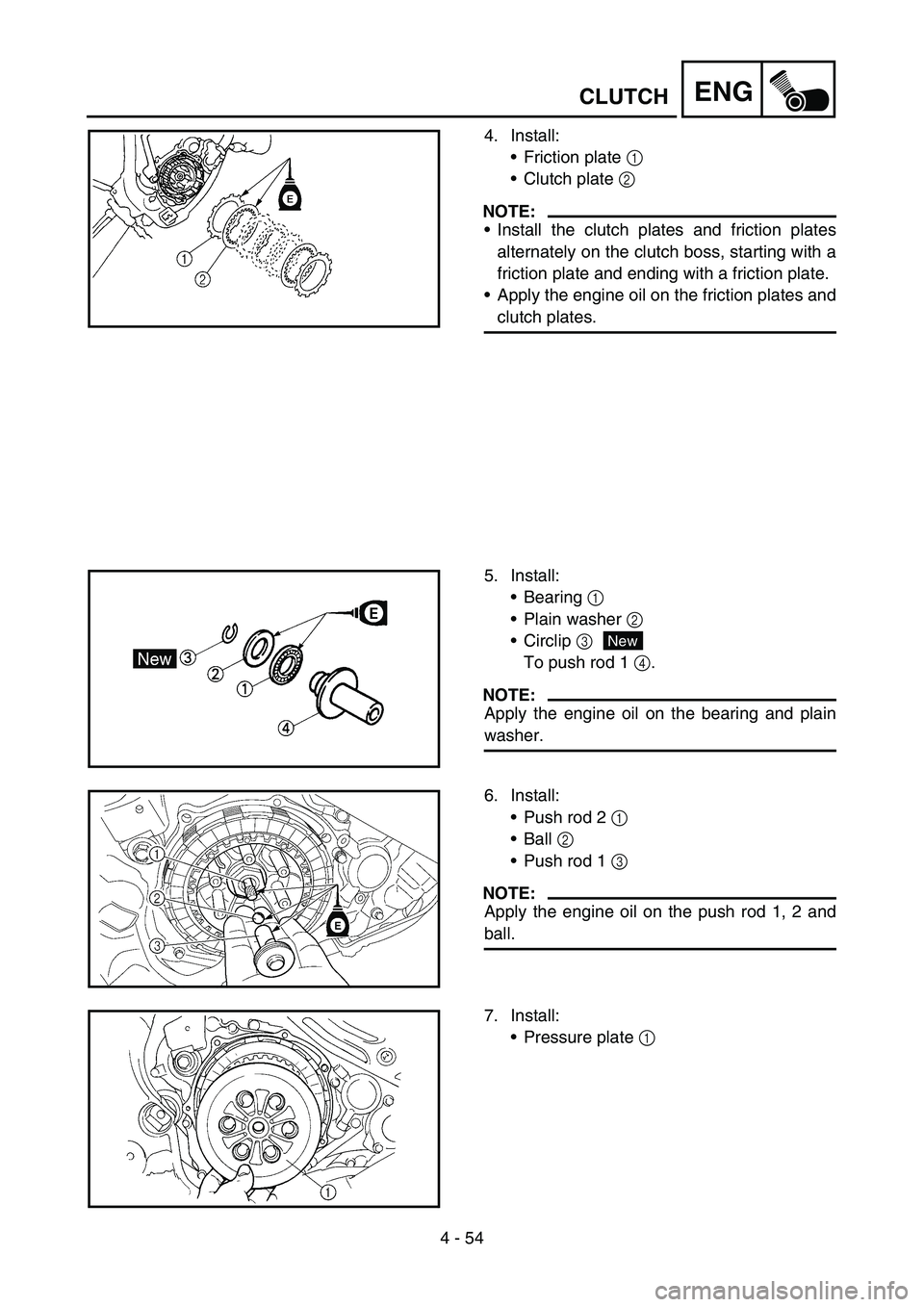
4. Install:
Friction plate 1
Clutch plate 2
NOTE:
Install the clutch plates and friction plates
alternately on the clutch boss, starting with a
friction plate and ending with a friction plate.
Apply the engine oil on the friction plates and
clutch plates.
5. Install:
Bearing 1
Plain washer 2
Circlip 3
To push rod 1 4.
NOTE:
Apply the engine oil on the bearing and plain
washer.
New
6. Install:
Push rod 2 1
Ball 2
Push rod 1 3
NOTE:
Apply the engine oil on the push rod 1, 2 and
ball.
7. Install:
Pressure plate 1
Page 350 of 650
4 - 55
ENGCLUTCH
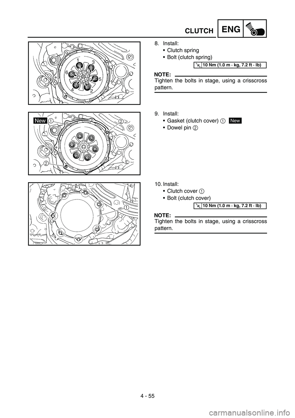
8. Install:
Clutch spring
Bolt (clutch spring)
NOTE:
Tighten the bolts in stage, using a crisscross
pattern.
T R..10 Nm (1.0 m · kg, 7.2 ft · lb)
9. Install:
Gasket (clutch cover) 1
Dowel pin 2
New
10. Install:
Clutch cover 1
Bolt (clutch cover)
NOTE:
Tighten the bolts in stage, using a crisscross
pattern.
T R..10 Nm (1.0 m · kg, 7.2 ft · lb)
Page 352 of 650
4 - 56
ENG
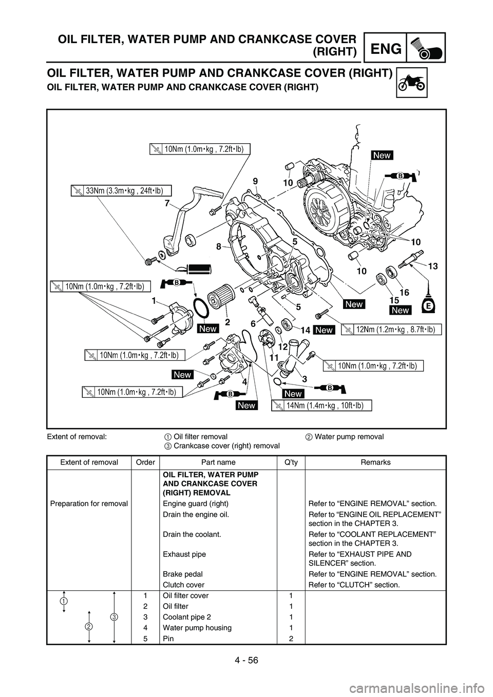
OIL FILTER, WATER PUMP AND CRANKCASE COVER
(RIGHT)
OIL FILTER, WATER PUMP AND CRANKCASE COVER (RIGHT)
OIL FILTER, WATER PUMP AND CRANKCASE COVER (RIGHT)
Extent of removal:
1 Oil filter removal
2 Water pump removal
3 Crankcase cover (right) removal
Extent of removal Order Part name Q’ty Remarks
OIL FILTER, WATER PUMP
AND CRANKCASE COVER
(RIGHT) REMOVAL
Preparation for removal Engine guard (right) Refer to “ENGINE REMOVAL” section.
Drain the engine oil. Refer to “ENGINE OIL REPLACEMENT”
section in the CHAPTER 3.
Drain the coolant. Refer to “COOLANT REPLACEMENT”
section in the CHAPTER 3.
Exhaust pipe Refer to “EXHAUST PIPE AND
SILENCER” section.
Brake pedal Refer to “ENGINE REMOVAL” section.
Clutch cover Refer to “CLUTCH” section.
1 Oil filter cover 1
2 Oil filter 1
3 Coolant pipe 2 1
4 Water pump housing 1
5Pin 2
1
2
3
Page 366 of 650
4 - 63
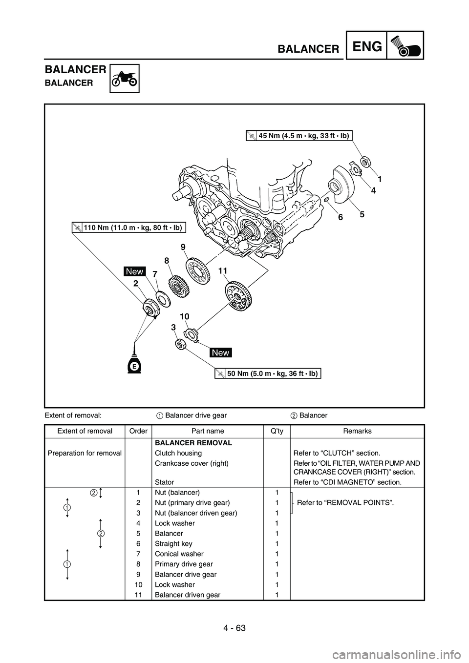
ENGBALANCER
BALANCER
BALANCER
Extent of removal:
1 Balancer drive gear
2 Balancer
Extent of removal Order Part name Q’ty Remarks
BALANCER REMOVAL
Preparation for removal Clutch housing Refer to “CLUTCH” section.
Crankcase cover (right) Refer to “OIL FILTER, WATER PUMP AND
CRANKCASE COVER (RIGHT)” section.
Stator Refer to “CDI MAGNETO” section.
1 Nut (balancer) 1
Refer to “REMOVAL POINTS”. 2 Nut (primary drive gear) 1
3 Nut (balancer driven gear) 1
4 Lock washer 1
5 Balancer 1
6 Straight key 1
7 Conical washer 1
8 Primary drive gear 1
9 Balancer drive gear 1
10 Lock washer 1
11 Balancer driven gear 1
2
1
2
1