compression ratio YAMAHA YZ450F 2009 Owners Manual
[x] Cancel search | Manufacturer: YAMAHA, Model Year: 2009, Model line: YZ450F, Model: YAMAHA YZ450F 2009Pages: 190, PDF Size: 12.39 MB
Page 23 of 190

2-1
GENERAL SPECIFICATIONS
SPECIFICATIONS
GENERAL SPECIFICATIONS
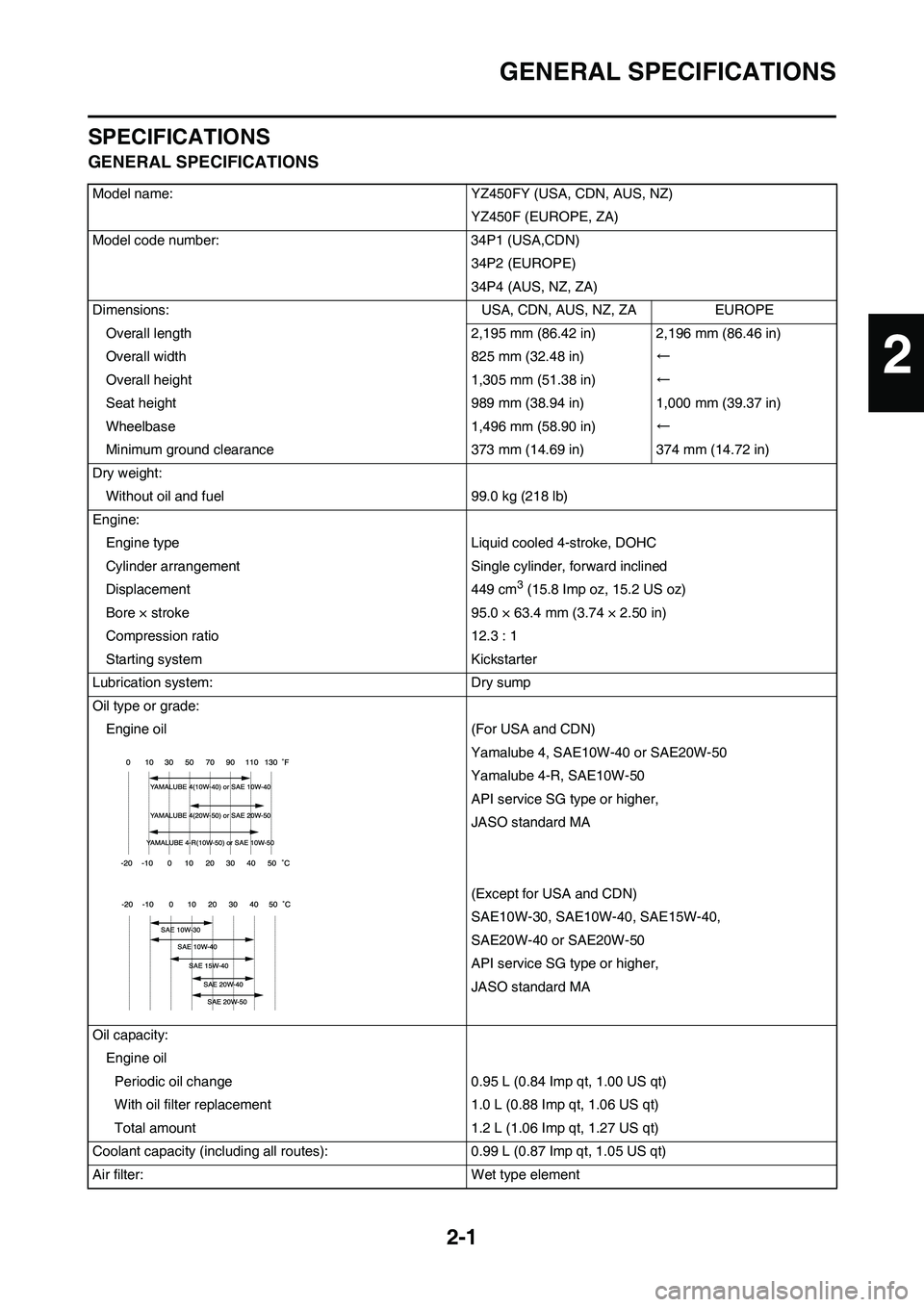
Model name: YZ450FY (USA, CDN, AUS, NZ)
YZ450F (EUROPE, ZA)
Model code number: 34P1 (USA,CDN)
34P2 (EUROPE)
34P4 (AUS, NZ, ZA)
Dimensions: USA, CDN, AUS, NZ, ZA EUROPE
Overall length 2,195 mm (86.42 in) 2,196 mm (86.46 in)
Overall width 825 mm (32.48 in)←
Overall height 1,305 mm (51.38 in)←
Seat height 989 mm (38.94 in) 1,000 mm (39.37 in)
Wheelbase 1,496 mm (58.90 in)←
Minimum ground clearance 373 mm (14.69 in) 374 mm (14.72 in)
Dry weight:
Without oil and fuel 99.0 kg (218 lb)
Engine:
Engine type Liquid cooled 4-stroke, DOHC
Cylinder arrangement Single cylinder, forward inclined
Displacement 449 cm
3 (15.8 Imp oz, 15.2 US oz)
Bore × stroke 95.0 × 63.4 mm (3.74 × 2.50 in)
Compression ratio 12.3 : 1
Starting system Kickstarter
Lubrication system: Dry sump
Oil type or grade:
Engine oil (For USA and CDN)
Yamalube 4, SAE10W-40 or SAE20W-50
Yamalube 4-R, SAE10W-50
API service SG type or higher,
JASO standard MA
(Except for USA and CDN)
SAE10W-30, SAE10W-40, SAE15W-40,
SAE20W-40 or SAE20W-50
API service SG type or higher,
JASO standard MA
Oil capacity:
Engine oil
Periodic oil change 0.95 L (0.84 Imp qt, 1.00 US qt)
With oil filter replacement 1.0 L (0.88 Imp qt, 1.06 US qt)
Total amount 1.2 L (1.06 Imp qt, 1.27 US qt)
Coolant capacity (including all routes): 0.99 L (0.87 Imp qt, 1.05 US qt)
Air filter: Wet type element
2
Page 87 of 190

4-17
CAMSHAFTS
Measurement steps:
a. Install the camshaft onto the cylin-
der head.
b. Position a strip of Plastigauge
®
"1" onto the camshaft.
c. Install the clip, dowel pins and
camshaft caps.
• Tighten the bolts (camshaft cap) in
a crisscross pattern from innermost
to outer caps.
• Do not turn the camshaft when
measuring clearance with the Plas-
tigauge
®.
d. Remove the camshaft caps and
measure the width of the Plasti-
gauge
® "1".
5. Measure:
• Camshaft outside diameter "a"
Out of specification→Replace the
camshaft.
Within specification→Replace
camshaft case and camshaft
caps as a set.CHECKING THE CAMSHAFT
SPROCKET
1. Inspect:
• Camshaft sprocket "1"
Wear/damage→Replace the
camshaft assembly and timing
chain as a set.
CHECKING THE
DECOMPRESSION SYSTEM
1. Check:
• Decompression system
Checking steps:
a. Check that the decompression
mechanism cam "1" moves
smoothly.
b. Check that the decompression
mechanism cam lever pin "2"
projects from the camshaft.
CHECKING THE TIMING CHAIN
TENSIONER
1. Check:
• While pressing the tensioner rod
lightly with fingers, use a thin
screwdriver "1" and wind the ten-
sioner rod up fully clockwise.
• When releasing the screwdriver
by pressing lightly with fingers,
make sure that the tensioner rod
will come out smoothly.
• If not, replace the tensioner as-
sembly.INSTALLING THE CAMSHAFT
1. Install:
• Exhaust camshaft "1"
• Intake camshaft "2"
Installation steps:
a. Turn the crankshaft counterclock-
wise with a wrench.
• Apply the molybdenum disulfide oil
on the camshafts.
• Apply the engine oil on the decom-
pression system.
b. Align the T.D.C. mark "a" on the
rotor with the align mark "b" on the
crankcase cover when piston is at
T.D.C. on compression stroke.
c. Fit the timing chain "3" onto both
camshaft sprockets and install the
camshafts on the cylinder head.
The camshafts should be installed
onto the cylinder head so that the
punch mark "c" on the exhaust cam-
shaft and the punch mark "d" on the
intake camshaft must align with the
cylinder head surface, as shown in
the illustration.
Camshaft-to-cap clear-
ance:
0.028–0.062 mm
(0.0011–0.0024 in)
in)
Bolt (camshaft cap):
10 Nm (1.0 m•kg, 7.2
ft•lb)
Camshaft outside diame-
ter:
21.959–21.972 mm
(0.8645–0.8650 in)
Page 184 of 190

7-6
CHASSIS
CHASSIS
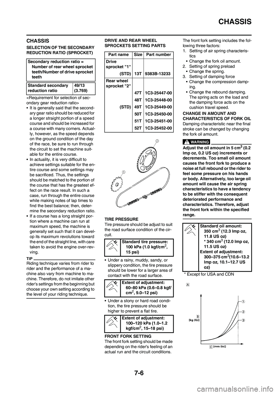
SELECTION OF THE SECONDARY
REDUCTION RATIO (SPROCKET)
• It is generally said that the second-
ary gear ratio should be reduced for
a longer straight portion of a speed
course and should be increased for
a course with many corners. Actual-
ly, however, as the speed depends
on the ground condition of the day
of the race, be sure to run through
the circuit to set the machine suit-
able for the entire course.
• In actuality, it is very difficult to
achieve settings suitable for the en-
tire course and some settings may
be sacrificed. Thus, the settings
should be matched to the portion of
the course that has the greatest ef-
fect on the race result. In such a
case, run through the entire course
while making notes of lap times to
find the best balance; then, deter-
mine the secondary reduction ratio.
• If a course has a long straight por-
tion where a machine can run at
maximum speed, the machine is
generally set such that it can devel-
op its maximum revolutions toward
the end of the straight line, with care
taken to avoid the engine over-rev-
ving.
Riding technique varies from rider to
rider and the performance of a ma-
chine also vary from machine to ma-
chine. Therefore, do not imitate other
rider's settings from the beginning but
choose your own setting according to
the level of your riding technique.
DRIVE AND REAR WHEEL
SPROCKETS SETTING PARTS
TIRE PRESSURE
Tire pressure should be adjust to suit
the road surface condition of the cir-
cuit.
• Under a rainy, muddy, sandy, or
slippery condition, the tire pressure
should be lower for a larger area of
contact with the road surface.
• Under a stony or hard road condi-
tion, the tire pressure should be
higher to prevent a flat tire.
FRONT FORK SETTING
The front fork setting should be made
depending on the rider's feeling of an
actual run and the circuit conditions.The front fork setting includes the fol-
lowing three factors:
1. Setting of air spring characteris-
tics
• Change the fork oil amount.
2. Setting of spring preload
• Change the spring.
3. Setting of damping force
• Change the compression damp-
ing.
• Change the rebound damping.
The spring acts on the load and
the damping force acts on the
cushion travel speed.
CHANGE IN AMOUNT AND
CHARACTERISTICS OF FORK OIL
Damping characteristic near the final
stroke can be changed by changing
the fork oil amount.
Adjust the oil amount in 5 cm3 (0.2
Imp oz, 0.2 US oz) increments or
decrements. Too small oil amount
causes the front fork to produce a
noise at full rebound or the rider to
feel some pressure on his hands
or body. Alternatively, too large oil
amount will cause the air spring
characteristics to have a tendency
to be stiffer with the consequent
deteriorated performance and
characteristics. Therefore, adjust
the front fork within the specified
range.
Secondary reduction ratio =
Number of rear wheel sprocket
teeth/Number of drive sprocket
teeth
Standard secondary
reduction ratio49/13
(3.769)
Part name Size Part number
Drive
sprocket "1"
(STD) 13T 9383B-13233
Rear wheel
sprocket "2"
47T 1C3-25447-00
48T 1C3-25448-00
(STD) 49T 1C3-25449-00
50T 1C3-25450-00
51T 1C3-25451-00
52T 1C3-25452-00
Standard tire pressure:
100 kPa (1.0 kgf/cm
2,
15 psi)
Extent of adjustment:
60–80 kPa (0.6–0.8 kgf/
cm
2, 9.0–12 psi)
Extent of adjustment:
100–120 kPa (1.0–1.2
kgf/cm
2, 15–18 psi)
Standard oil amount:
350 cm3 (12.3 Imp oz,
11.8 US oz)
* 340 cm
3 (12.0 Imp oz,
11.5 US oz)
Extent of adjustment:
300–375 cm
3(10.6–13.2
Imp oz, 10.1–12.7 US
oz)
* Except for USA and CDN