seat adjustment YAMAHA YZ450F 2009 Owners Manual
[x] Cancel search | Manufacturer: YAMAHA, Model Year: 2009, Model line: YZ450F, Model: YAMAHA YZ450F 2009Pages: 190, PDF Size: 12.39 MB
Page 10 of 190
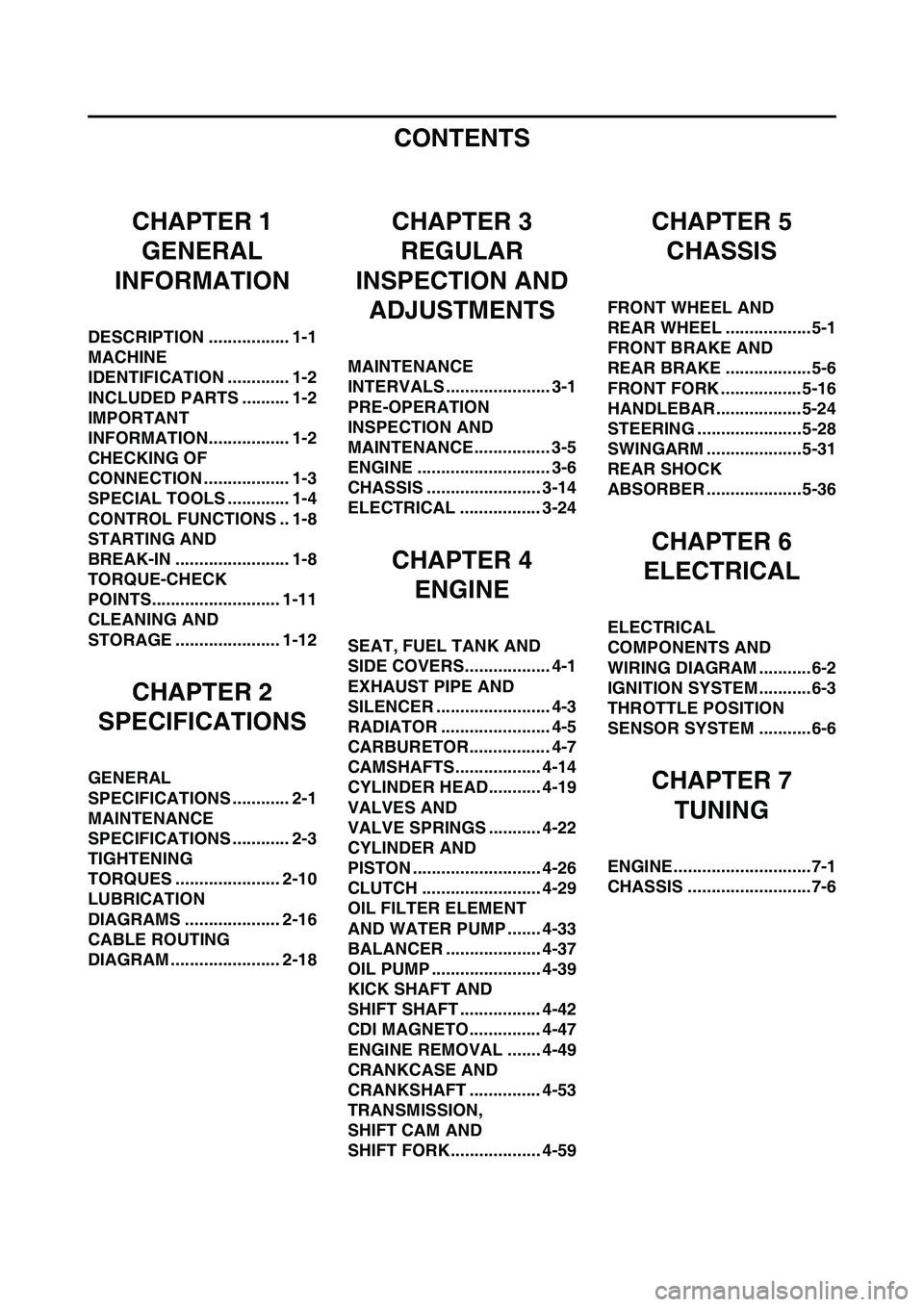
CONTENTS
CHAPTER 1
GENERAL
INFORMATION
DESCRIPTION ................. 1-1
MACHINE
IDENTIFICATION ............. 1-2
INCLUDED PARTS .......... 1-2
IMPORTANT
INFORMATION................. 1-2
CHECKING OF
CONNECTION .................. 1-3
SPECIAL TOOLS ............. 1-4
CONTROL FUNCTIONS .. 1-8
STARTING AND
BREAK-IN ........................ 1-8
TORQUE-CHECK
POINTS........................... 1-11
CLEANING AND
STORAGE ...................... 1-12
CHAPTER 2
SPECIFICATIONS
GENERAL
SPECIFICATIONS ............ 2-1
MAINTENANCE
SPECIFICATIONS ............ 2-3
TIGHTENING
TORQUES ...................... 2-10
LUBRICATION
DIAGRAMS .................... 2-16
CABLE ROUTING
DIAGRAM ....................... 2-18
CHAPTER 3
REGULAR
INSPECTION AND
ADJUSTMENTS
MAINTENANCE
INTERVALS ...................... 3-1
PRE-OPERATION
INSPECTION AND
MAINTENANCE................ 3-5
ENGINE ............................ 3-6
CHASSIS ........................ 3-14
ELECTRICAL ................. 3-24
CHAPTER 4
ENGINE
SEAT, FUEL TANK AND
SIDE COVERS.................. 4-1
EXHAUST PIPE AND
SILENCER ........................ 4-3
RADIATOR ....................... 4-5
CARBURETOR................. 4-7
CAMSHAFTS.................. 4-14
CYLINDER HEAD........... 4-19
VALVES AND
VALVE SPRINGS ........... 4-22
CYLINDER AND
PISTON ........................... 4-26
CLUTCH ......................... 4-29
OIL FILTER ELEMENT
AND WATER PUMP ....... 4-33
BALANCER .................... 4-37
OIL PUMP ....................... 4-39
KICK SHAFT AND
SHIFT SHAFT ................. 4-42
CDI MAGNETO............... 4-47
ENGINE REMOVAL ....... 4-49
CRANKCASE AND
CRANKSHAFT ............... 4-53
TRANSMISSION,
SHIFT CAM AND
SHIFT FORK................... 4-59
CHAPTER 5
CHASSIS
FRONT WHEEL AND
REAR WHEEL ..................5-1
FRONT BRAKE AND
REAR BRAKE ..................5-6
FRONT FORK ................. 5-16
HANDLEBAR..................5-24
STEERING ......................5-28
SWINGARM ....................5-31
REAR SHOCK
ABSORBER ....................5-36
CHAPTER 6
ELECTRICAL
ELECTRICAL
COMPONENTS AND
WIRING DIAGRAM ...........6-2
IGNITION SYSTEM...........6-3
THROTTLE POSITION
SENSOR SYSTEM ...........6-6
CHAPTER 7
TUNING
ENGINE.............................7-1
CHASSIS ..........................7-6
Page 26 of 190
2-4
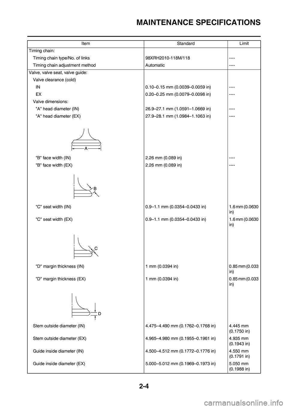
MAINTENANCE SPECIFICATIONS
Timing chain:
Timing chain type/No. of links 98XRH2010-118M/118 ----
Timing chain adjustment method Automatic ----
Valve, valve seat, valve guide:
Valve clearance (cold)
IN 0.10–0.15 mm (0.0039–0.0059 in) ----
EX 0.20–0.25 mm (0.0079–0.0098 in) ----
Valve dimensions:
"A" head diameter (IN) 26.9–27.1 mm (1.0591–1.0669 in) ----
"A" head diameter (EX) 27.9–28.1 mm (1.0984–1.1063 in) ----
"B" face width (IN) 2.26 mm (0.089 in) ----
"B" face width (EX) 2.26 mm (0.089 in) ----
"C" seat width (IN) 0.9–1.1 mm (0.0354–0.0433 in) 1.6 mm (0.0630
in)
"C" seat width (EX) 0.9–1.1 mm (0.0354–0.0433 in) 1.6 mm (0.0630
in)
"D" margin thickness (IN) 1 mm (0.0394 in) 0.85 mm (0.033
in)
"D" margin thickness (EX) 1 mm (0.0394 in) 0.85 mm (0.033
in)
Stem outside diameter (IN) 4.475–4.490 mm (0.1762–0.1768 in) 4.445 mm
(0.1750 in)
Stem outside diameter (EX) 4.965–4.980 mm (0.1955–0.1961 in) 4.935 mm
(0.1943 in)
Guide inside diameter (IN) 4.500–4.512 mm (0.1772–0.1776 in) 4.550 mm
(0.1791 in)
Guide inside diameter (EX) 5.000–5.012 mm (0.1969–0.1973 in) 5.050 mm
(0.1988 in) Item Standard Limit
Page 47 of 190
3-1
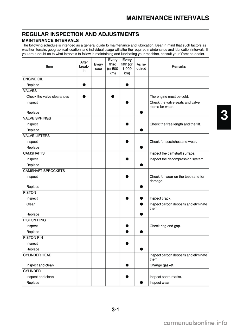
MAINTENANCE INTERVALS
REGULAR INSPECTION AND ADJUSTMENTS
MAINTENANCE INTERVALS
The following schedule is intended as a general guide to maintenance and lubrication. Bear in mind that such factors as
weather, terrain, geographical location, and individual usage will alter the required maintenance and lubrication intervals. If
you are a doubt as to what intervals to follow in maintaining and lubricating your machine, consult your Yamaha dealer.
ItemAfter
break-
inEvery
race
Every
third
(or 500
km)Every
fifth (or
1,000
km)
As re-
quiredRemarks
ENGINE OIL
Replace●●
VALVES
Check the valve clearances●●The engine must be cold.
Inspect●Check the valve seats and valve
stems for wear.
Replace●
VALVE SPRINGS
Inspect●Check the free length and the tilt.
Replace●
VALVE LIFTERS
Inspect●Check for scratches and wear.
Replace●
CAMSHAFTS Inspect the camshaft surface.
Inspect●Inspect the decompression system.
Replace●
CAMSHAFT SPROCKETS
Inspect●Check for wear on the teeth and for
damage.
Replace●
PISTON
Inspect●●Inspect crack.
Clean●Inspect carbon deposits and eliminate
them.
Replace●
PISTON RING
Inspect●Check ring end gap.
Replace●●
PISTON PIN
Inspect●
Replace●
CYLINDER HEAD Inspect carbon deposits and eliminate
them.
Inspect and clean●Change gasket.
CYLINDER
Inspect and clean●Inspect score marks.
Replace●Inspect wear.
3
Page 54 of 190
3-8
ENGINE
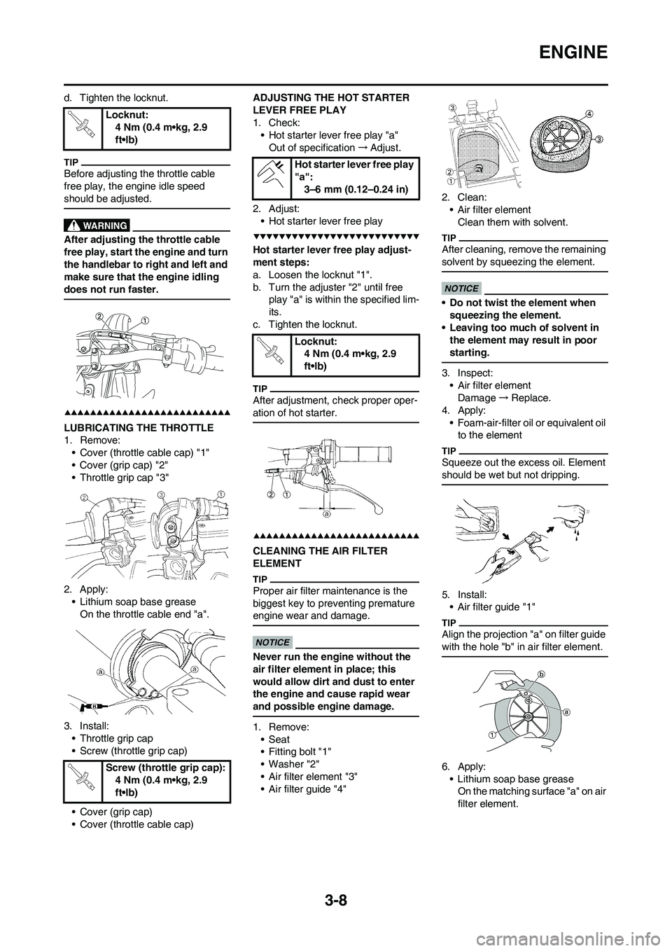
d. Tighten the locknut.
Before adjusting the throttle cable
free play, the engine idle speed
should be adjusted.
After adjusting the throttle cable
free play, start the engine and turn
the handlebar to right and left and
make sure that the engine idling
does not run faster.
LUBRICATING THE THROTTLE
1. Remove:
• Cover (throttle cable cap) "1"
• Cover (grip cap) "2"
• Throttle grip cap "3"
2. Apply:
• Lithium soap base grease
On the throttle cable end "a".
3. Install:
• Throttle grip cap
• Screw (throttle grip cap)
• Cover (grip cap)
• Cover (throttle cable cap)ADJUSTING THE HOT STARTER
LEVER FREE PLAY
1. Check:
• Hot starter lever free play "a"
Out of specification→Adjust.
2. Adjust:
• Hot starter lever free play
Hot starter lever free play adjust-
ment steps:
a. Loosen the locknut "1".
b. Turn the adjuster "2" until free
play "a" is within the specified lim-
its.
c. Tighten the locknut.
After adjustment, check proper oper-
ation of hot starter.
CLEANING THE AIR FILTER
ELEMENT
Proper air filter maintenance is the
biggest key to preventing premature
engine wear and damage.
Never run the engine without the
air filter element in place; this
would allow dirt and dust to enter
the engine and cause rapid wear
and possible engine damage.
1. Remove:
•Seat
• Fitting bolt "1"
•Washer "2"
• Air filter element "3"
• Air filter guide "4"2. Clean:
• Air filter element
Clean them with solvent.
After cleaning, remove the remaining
solvent by squeezing the element.
• Do not twist the element when
squeezing the element.
• Leaving too much of solvent in
the element may result in poor
starting.
3. Inspect:
• Air filter element
Damage→Replace.
4. Apply:
• Foam-air-filter oil or equivalent oil
to the element
Squeeze out the excess oil. Element
should be wet but not dripping.
5. Install:
• Air filter guide "1"
Align the projection "a" on filter guide
with the hole "b" in air filter element.
6. Apply:
• Lithium soap base grease
On the matching surface "a" on air
filter element. Locknut:
4 Nm (0.4 m•kg, 2.9
ft•lb)
Screw (throttle grip cap):
4 Nm (0.4 m•kg, 2.9
ft•lb)
Hot starter lever free play
"a":
3–6 mm (0.12–0.24 in)
Locknut:
4 Nm (0.4 m•kg, 2.9
ft•lb)
Page 56 of 190
3-10
ENGINE
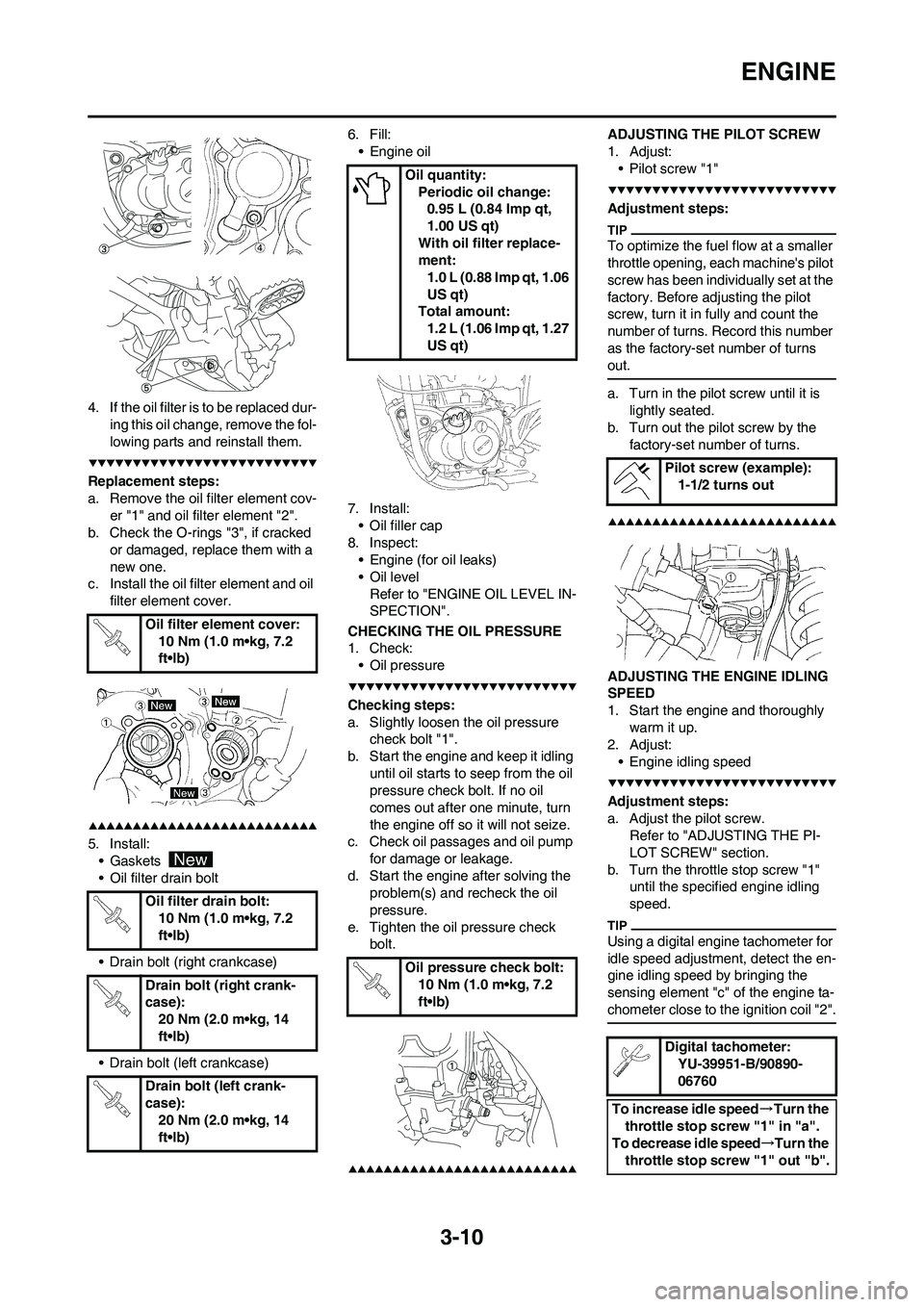
4. If the oil filter is to be replaced dur-
ing this oil change, remove the fol-
lowing parts and reinstall them.
Replacement steps:
a. Remove the oil filter element cov-
er "1" and oil filter element "2".
b. Check the O-rings "3", if cracked
or damaged, replace them with a
new one.
c. Install the oil filter element and oil
filter element cover.
5. Install:
• Gaskets
• Oil filter drain bolt
• Drain bolt (right crankcase)
• Drain bolt (left crankcase)6. Fill:
• Engine oil
7. Install:
• Oil filler cap
8. Inspect:
• Engine (for oil leaks)
• Oil level
Refer to "ENGINE OIL LEVEL IN-
SPECTION".
CHECKING THE OIL PRESSURE
1. Check:
• Oil pressure
Checking steps:
a. Slightly loosen the oil pressure
check bolt "1".
b. Start the engine and keep it idling
until oil starts to seep from the oil
pressure check bolt. If no oil
comes out after one minute, turn
the engine off so it will not seize.
c. Check oil passages and oil pump
for damage or leakage.
d. Start the engine after solving the
problem(s) and recheck the oil
pressure.
e. Tighten the oil pressure check
bolt.
ADJUSTING THE PILOT SCREW
1. Adjust:
•Pilot screw "1"
Adjustment steps:
To optimize the fuel flow at a smaller
throttle opening, each machine's pilot
screw has been individually set at the
factory. Before adjusting the pilot
screw, turn it in fully and count the
number of turns. Record this number
as the factory-set number of turns
out.
a. Turn in the pilot screw until it is
lightly seated.
b. Turn out the pilot screw by the
factory-set number of turns.
ADJUSTING THE ENGINE IDLING
SPEED
1. Start the engine and thoroughly
warm it up.
2. Adjust:
• Engine idling speed
Adjustment steps:
a. Adjust the pilot screw.
Refer to "ADJUSTING THE PI-
LOT SCREW" section.
b. Turn the throttle stop screw "1"
until the specified engine idling
speed.
Using a digital engine tachometer for
idle speed adjustment, detect the en-
gine idling speed by bringing the
sensing element "c" of the engine ta-
chometer close to the ignition coil "2".
Oil filter element cover:
10 Nm (1.0 m•kg, 7.2
ft•lb)
Oil filter drain bolt:
10 Nm (1.0 m•kg, 7.2
ft•lb)
Drain bolt (right crank-
case):
20 Nm (2.0 m•kg, 14
ft•lb)
Drain bolt (left crank-
case):
20 Nm (2.0 m•kg, 14
ft•lb)
Oil quantity:
Periodic oil change:
0.95 L (0.84 Imp qt,
1.00 US qt)
With oil filter replace-
ment:
1.0 L (0.88 Imp qt, 1.06
US qt)
Total amount:
1.2 L (1.06 Imp qt, 1.27
US qt)
Oil pressure check bolt:
10 Nm (1.0 m•kg, 7.2
ft•lb)
Pilot screw (example):
1-1/2 turns out
Digital tachometer:
YU-39951-B/90890-
06760
To increase idle speed→Turn the
throttle stop screw "1" in "a".
To decrease idle speed→Turn the
throttle stop screw "1" out "b".
Page 57 of 190
3-11
ENGINE
ADJUSTING THE VALVE
CLEARANCE
• This section is intended for those
who have basic knowledge and skill
concerning the servicing of Yama-
ha motorcycles (e.g., Yamaha deal-
ers, service engineers, etc.) Those
who have little knowledge and skill
concerning servicing are requested
not to undertake inspection, adjust-
ment, disassembly, or reassembly
only by reference to this manual. It
may lead to servicing trouble and
mechanical damage.
• The valve clearance should be ad-
justed when the engine is cool to
the touch.
• The piston must be at Top Dead
Center (T.D.C.) on compression
stroke to check or adjust the valve
clearance.
1. Remove:
• Seat
• Fuel tank
Refer to "SEAT, FUEL TANK
AND SIDE COVERS" section in
the CHAPTER 4.
2. Remove:
• Spark plug
• Engine upper bracket
• Hot starter plunger
Refer to "CARBURETOR" section
in the CHAPTER 4.
• Cylinder head cover
Refer to "CAMSHAFTS" section
in the CHAPTER 4.
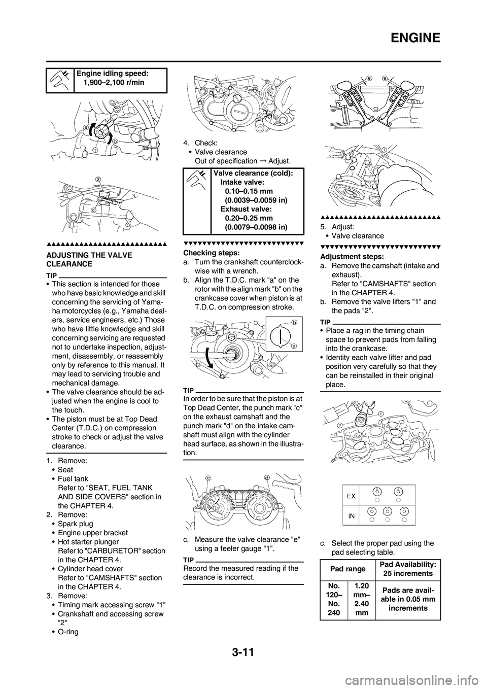
3. Remove:
• Timing mark accessing screw "1"
• Crankshaft end accessing screw
"2"
• O-ring4. Check:
• Valve clearance
Out of specification→Adjust.
Checking steps:
a. Turn the crankshaft counterclock-
wise with a wrench.
b. Align the T.D.C. mark "a" on the
rotor with the align mark "b" on the
crankcase cover when piston is at
T.D.C. on compression stroke.
In order to be sure that the piston is at
Top Dead Center, the punch mark "c"
on the exhaust camshaft and the
punch mark "d" on the intake cam-
shaft must align with the cylinder
head surface, as shown in the illustra-
tion.
c. Measure the valve clearance "e"
using a feeler gauge "1".
Record the measured reading if the
clearance is incorrect.
5. Adjust:
• Valve clearance
Adjustment steps:
a. Remove the camshaft (intake and
exhaust).
Refer to "CAMSHAFTS" section
in the CHAPTER 4.
b. Remove the valve lifters "1" and
the pads "2".
• Place a rag in the timing chain
space to prevent pads from falling
into the crankcase.
• Identity each valve lifter and pad
position very carefully so that they
can be reinstalled in their original
place.
c. Select the proper pad using the
pad selecting table. Engine idling speed:
1,900–2,100 r/min
Valve clearance (cold):
Intake valve:
0.10–0.15 mm
(0.0039–0.0059 in)
Exhaust valve:
0.20–0.25 mm
(0.0079–0.0098 in)
Pad rangePad Availability:
25 increments
No.
120–
No.
2401.20
mm–
2.40
mmPads are avail-
able in 0.05 mm
increments
Page 71 of 190
4-1
SEAT, FUEL TANK AND SIDE COVERS
ENGINE
This section is intended for those who have basic knowledge and skill concerning the servicing of Yamaha motorcycles
(e.g., Yamaha dealers, service engineers, etc.) Those who have little knowledge and skill concerning servicing are request-
ed not to undertake inspection, adjustment, disassembly, or reassembly only by reference to this manual. It may lead to
servicing trouble and mechanical damage.
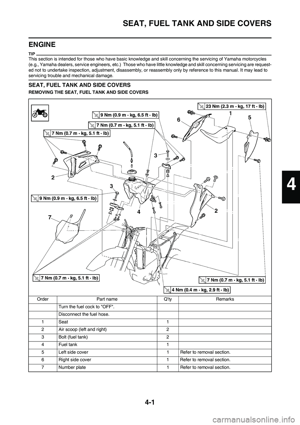
SEAT, FUEL TANK AND SIDE COVERS
REMOVING THE SEAT, FUEL TANK AND SIDE COVERS
Order Part name Q'ty Remarks
Turn the fuel cock to "OFF".
Disconnect the fuel hose.
1 Seat 1
2 Air scoop (left and right) 2
3 Bolt (fuel tank) 2
4 Fuel tank 1
5 Left side cover 1 Refer to removal section.
6 Right side cover 1 Refer to removal section.
7 Number plate 1 Refer to removal section.
4
Page 80 of 190
4-10
CARBURETOR
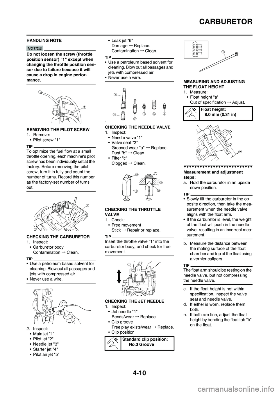
HANDLING NOTE
Do not loosen the screw (throttle
position sensor) "1" except when
changing the throttle position sen-
sor due to failure because it will
cause a drop in engine perfor-
mance.
REMOVING THE PILOT SCREW
1. Remove:
• Pilot screw "1"
To optimize the fuel flow at a small
throttle opening, each machine's pilot
screw has been individually set at the
factory. Before removing the pilot
screw, turn it in fully and count the
number of turns. Record this number
as the factory-set number of turns
out.
CHECKING THE CARBURETOR
1. Inspect:
• Carburetor body
Contamination→Clean.
• Use a petroleum based solvent for
cleaning. Blow out all passages and
jets with compressed air.
• Never use a wire.
2. Inspect:
•Main jet "1"
• Pilot jet "2"
• Needle jet "3"
• Starter jet "4"
• Pilot air jet "5"•Leak jet "6"
Damage→Replace.
Contamination→Clean.
• Use a petroleum based solvent for
cleaning. Blow out all passages and
jets with compressed air.
• Never use a wire.
CHECKING THE NEEDLE VALVE
1. Inspect:
• Needle valve "1"
• Valve seat "2"
Grooved wear "a" →Replace.
Dust "b" →Clean.
•Filter "c"
Clogged→Clean.
CHECKING THE THROTTLE
VALVE
1. Check:
• Free movement
Stick→Repair or replace.
Insert the throttle valve "1" into the
carburetor body, and check for free
movement.
CHECKING THE JET NEEDLE
1. Inspect:
• Jet needle "1"
Bends/wear→Replace.
• Clip groove
Free play exists/wear→Replace.
• Clip positionMEASURING AND ADJUSTING
THE FLOAT HEIGHT
1. Measure:
• Float height "a"
Out of specification→Adjust.
Measurement and adjustment
steps:
a. Hold the carburetor in an upside
down position.
• Slowly tilt the carburetor in the op-
posite direction, then take the mea-
surement when the needle valve
aligns with the float arm.
• If the carburetor is level, the weight
of the float will push in the needle
valve, resulting in an incorrect mea-
surement.
b. Measure the distance between
the mating surface of the float
chamber and top of the float using
a vernier calipers.
The float arm should be resting on the
needle valve, but not compressing
the needle valve.
c. If the float height is not within
specification, inspect the valve
seat and needle valve.
d. If either is worn, replace them
both.
e. If both are fine, adjust the float
height by bending the float tab "b"
on the float.
Standard clip position:
No.3 Groove
Float height:
8.0 mm (0.31 in)
Page 185 of 190
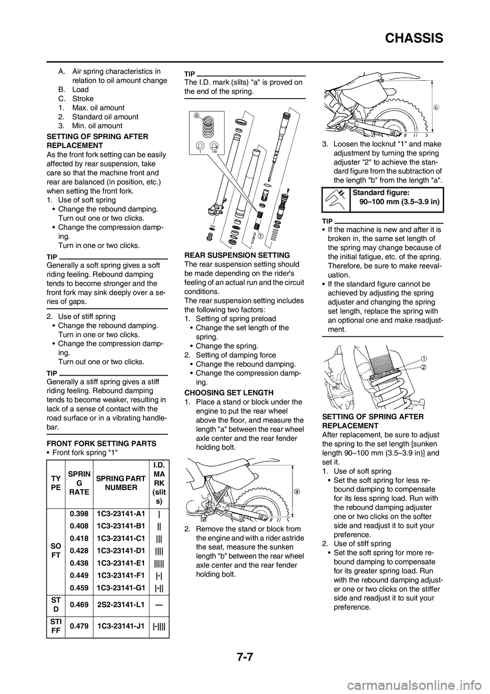
7-7
CHASSIS
A. Air spring characteristics in
relation to oil amount change
B. Load
C. Stroke
1. Max. oil amount
2. Standard oil amount
3. Min. oil amount
SETTING OF SPRING AFTER
REPLACEMENT
As the front fork setting can be easily
affected by rear suspension, take
care so that the machine front and
rear are balanced (in position, etc.)
when setting the front fork.
1. Use of soft spring
• Change the rebound damping.
Turn out one or two clicks.
• Change the compression damp-
ing.
Turn in one or two clicks.
Generally a soft spring gives a soft
riding feeling. Rebound damping
tends to become stronger and the
front fork may sink deeply over a se-
ries of gaps.
2. Use of stiff spring
• Change the rebound damping.
Turn in one or two clicks.
• Change the compression damp-
ing.
Turn out one or two clicks.
Generally a stiff spring gives a stiff
riding feeling. Rebound damping
tends to become weaker, resulting in
lack of a sense of contact with the
road surface or in a vibrating handle-
bar.
FRONT FORK SETTING PARTS
• Front fork spring "1"
The I.D. mark (slits) "a" is proved on
the end of the spring.
REAR SUSPENSION SETTING
The rear suspension setting should
be made depending on the rider's
feeling of an actual run and the circuit
conditions.
The rear suspension setting includes
the following two factors:
1. Setting of spring preload
• Change the set length of the
spring.
• Change the spring.
2. Setting of damping force
• Change the rebound damping.
• Change the compression damp-
ing.
CHOOSING SET LENGTH
1. Place a stand or block under the
engine to put the rear wheel
above the floor, and measure the
length "a" between the rear wheel
axle center and the rear fender
holding bolt.
2. Remove the stand or block from
the engine and with a rider astride
the seat, measure the sunken
length "b" between the rear wheel
axle center and the rear fender
holding bolt.3. Loosen the locknut "1" and make
adjustment by turning the spring
adjuster "2" to achieve the stan-
dard figure from the subtraction of
the length "b" from the length "a".
• If the machine is new and after it is
broken in, the same set length of
the spring may change because of
the initial fatigue, etc. of the spring.
Therefore, be sure to make reeval-
uation.
• If the standard figure cannot be
achieved by adjusting the spring
adjuster and changing the spring
set length, replace the spring with
an optional one and make readjust-
ment.
SETTING OF SPRING AFTER
REPLACEMENT
After replacement, be sure to adjust
the spring to the set length [sunken
length 90–100 mm (3.5–3.9 in)] and
set it.
1. Use of soft spring
• Set the soft spring for less re-
bound damping to compensate
for its less spring load. Run with
the rebound damping adjuster
one or two clicks on the softer
side and readjust it to suit your
preference.
2. Use of stiff spring
• Set the soft spring for more re-
bound damping to compensate
for its greater spring load. Run
with the rebound damping adjust-
er one or two clicks on the stiffer
side and readjust it to suit your
preference. TY
PESPRIN
G
RATESPRING PART
NUMBERI.D.
MA
RK
(slit
s)
SO
FT0.398 1C3-23141-A1 |
0.408 1C3-23141-B1 ||
0.418 1C3-23141-C1 |||
0.428 1C3-23141-D1 ||||
0.438 1C3-23141-E1 |||||
0.449 1C3-23141-F1 |-|
0.459 1C3-23141-G1 |-||
ST
D0.469 2S2-23141-L1 —
STI
FF0.479 1C3-23141-J1 |-||||
Standard figure:
90–100 mm (3.5–3.9 in)
Page 186 of 190
7-8
CHASSIS
Adjusting the rebound damping will
be followed more or less by a change
in the compression damping. For cor-
rection, turn the low compression
damping adjuster on the softer side.
When using a rear shock absorber
other than currently installed, use
the one whose overall length "a"
does not exceed the standard as it
may result in faulty performance.
Never use one whose overall
length is greater than standard.
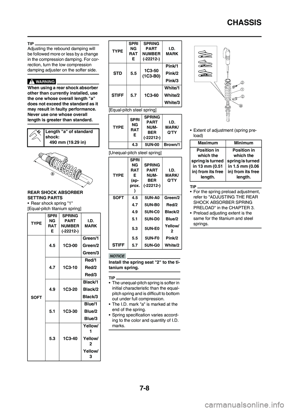
REAR SHOCK ABSORBER
SETTING PARTS
• Rear shock spring "1"
[Equal-pitch titanium spring][Equal-pitch steel spring]
[Unequal-pitch steel spring]
Install the spring seat "2" to the ti-
tanium spring.
• The unequal-pitch spring is softer in
initial characteristic than the equal-
pitch spring and is difficult to bottom
out under full compression.
• The I.D. mark "a" is marked at the
end of the spring.
• Spring specification varies accord-
ing to the color and quantity of I.D.
marks.
• Extent of adjustment (spring pre-
load)
• For the spring preload adjustment,
refer to "ADJUSTING THE REAR
SHOCK ABSORBER SPRING
PRELOAD" in the CHAPTER 3.
• Preload adjusting extent is the
same for the titanium and steel
springs.
Length "a" of standard
shock:
490 mm (19.29 in)
TYPESPRI
NG
RAT
ESPRING
PART
NUMBER
(-22212-)I.D.
MARK
SOFT
Green/1
4.5 1C3-00 Green/2
Green/3
Red/1
4.7 1C3-10 Red/2
Red/3
Black/1
4.9 1C3-20 Black/2
Black/3
Blue/1
5.1 1C3-30 Blue/2
Blue/3
Yellow/
1
5.3 1C3-40 Yellow/
2
Yellow/
3
1C3-50
(1C3-B0)Pink/1
STD 5.5 Pink/2
Pink/3
White/1
STIFF 5.7 1C3-60 White/2
White/3
TYPESPRI
NG
RAT
ESPRING
PART
NUM-
BER
(-22212-)I.D.
MARK/
Q'TY
4.3 5UN-00 Brown/1
TYPESPRI
NG
RAT
E
(ap-
prox.
)SPRING
PART
NUM-
BER
(-22212-)I.D.
MARK/
Q'TY
SOFT 4.5 5UN-A0 Green/2
4.7 5UN-B0 Red/2
4.9 5UN-C0 Black/2
5.1 5UN-D0 Blue/2
STIFF
5.3 5UN-E0Yellow/
2
5.5 5UN-F0 Pink/2
5.7 5UN-G0 White/2 TYPESPRI
NG
RAT
ESPRING
PART
NUMBER
(-22212-)I.D.
MARK
Maximum Minimum
Position in
which the
spring is turned
in 13 mm (0.51
in) from its free
length.Position in
which the
spring is turned
in 1.5 mm (0.06
in) from its free
length.