sensor YAMAHA YZ450F 2009 Owners Manual
[x] Cancel search | Manufacturer: YAMAHA, Model Year: 2009, Model line: YZ450F, Model: YAMAHA YZ450F 2009Pages: 190, PDF Size: 12.39 MB
Page 10 of 190
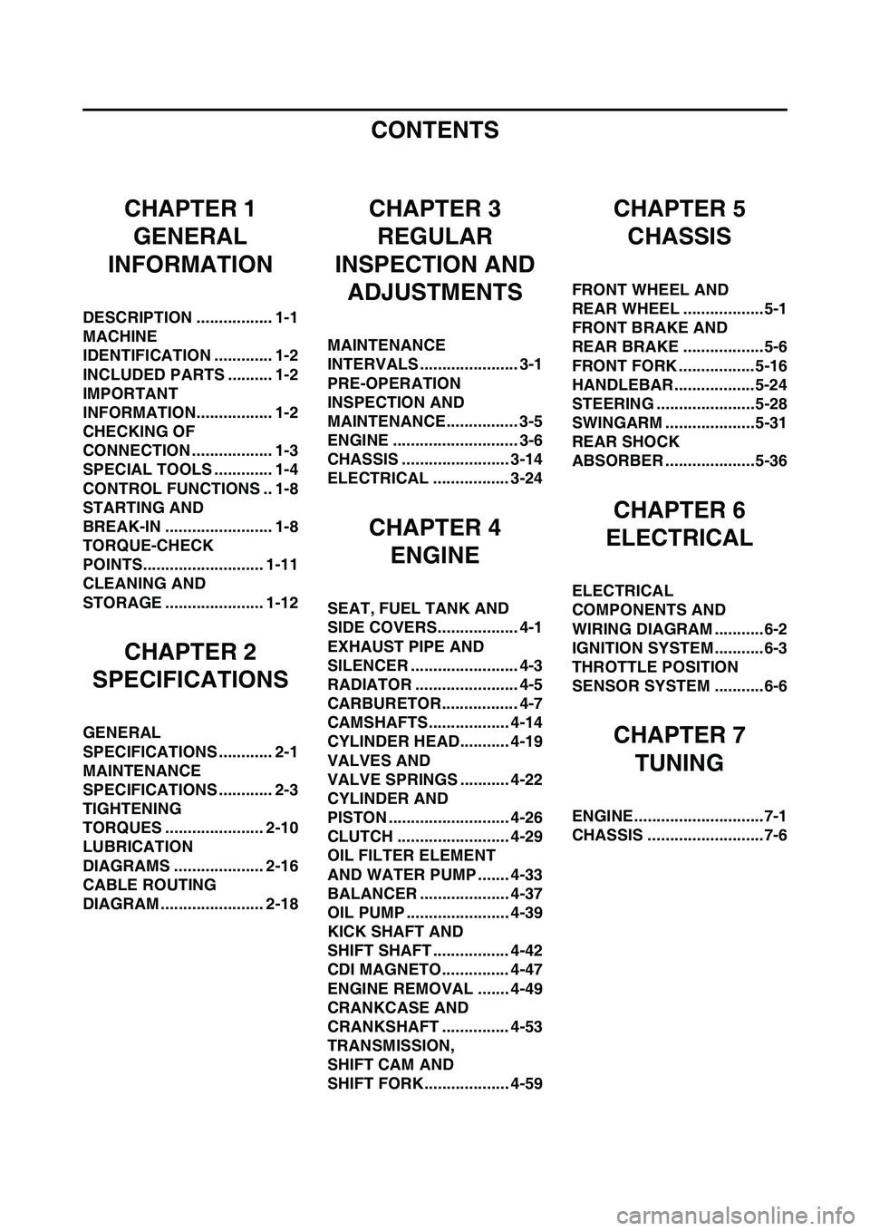
CONTENTS
CHAPTER 1
GENERAL
INFORMATION
DESCRIPTION ................. 1-1
MACHINE
IDENTIFICATION ............. 1-2
INCLUDED PARTS .......... 1-2
IMPORTANT
INFORMATION................. 1-2
CHECKING OF
CONNECTION .................. 1-3
SPECIAL TOOLS ............. 1-4
CONTROL FUNCTIONS .. 1-8
STARTING AND
BREAK-IN ........................ 1-8
TORQUE-CHECK
POINTS........................... 1-11
CLEANING AND
STORAGE ...................... 1-12
CHAPTER 2
SPECIFICATIONS
GENERAL
SPECIFICATIONS ............ 2-1
MAINTENANCE
SPECIFICATIONS ............ 2-3
TIGHTENING
TORQUES ...................... 2-10
LUBRICATION
DIAGRAMS .................... 2-16
CABLE ROUTING
DIAGRAM ....................... 2-18
CHAPTER 3
REGULAR
INSPECTION AND
ADJUSTMENTS
MAINTENANCE
INTERVALS ...................... 3-1
PRE-OPERATION
INSPECTION AND
MAINTENANCE................ 3-5
ENGINE ............................ 3-6
CHASSIS ........................ 3-14
ELECTRICAL ................. 3-24
CHAPTER 4
ENGINE
SEAT, FUEL TANK AND
SIDE COVERS.................. 4-1
EXHAUST PIPE AND
SILENCER ........................ 4-3
RADIATOR ....................... 4-5
CARBURETOR................. 4-7
CAMSHAFTS.................. 4-14
CYLINDER HEAD........... 4-19
VALVES AND
VALVE SPRINGS ........... 4-22
CYLINDER AND
PISTON ........................... 4-26
CLUTCH ......................... 4-29
OIL FILTER ELEMENT
AND WATER PUMP ....... 4-33
BALANCER .................... 4-37
OIL PUMP ....................... 4-39
KICK SHAFT AND
SHIFT SHAFT ................. 4-42
CDI MAGNETO............... 4-47
ENGINE REMOVAL ....... 4-49
CRANKCASE AND
CRANKSHAFT ............... 4-53
TRANSMISSION,
SHIFT CAM AND
SHIFT FORK................... 4-59
CHAPTER 5
CHASSIS
FRONT WHEEL AND
REAR WHEEL ..................5-1
FRONT BRAKE AND
REAR BRAKE ..................5-6
FRONT FORK ................. 5-16
HANDLEBAR..................5-24
STEERING ......................5-28
SWINGARM ....................5-31
REAR SHOCK
ABSORBER ....................5-36
CHAPTER 6
ELECTRICAL
ELECTRICAL
COMPONENTS AND
WIRING DIAGRAM ...........6-2
IGNITION SYSTEM...........6-3
THROTTLE POSITION
SENSOR SYSTEM ...........6-6
CHAPTER 7
TUNING
ENGINE.............................7-1
CHASSIS ..........................7-6
Page 40 of 190
2-18
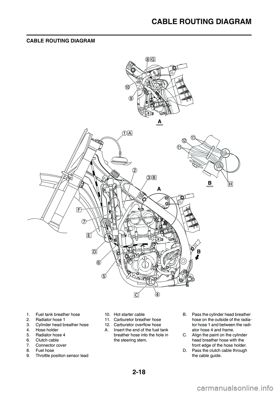
CABLE ROUTING DIAGRAM
CABLE ROUTING DIAGRAM
1. Fuel tank breather hose
2. Radiator hose 1
3. Cylinder head breather hose
4. Hose holder
5. Radiator hose 4
6. Clutch cable
7. Connector cover
8. Fuel hose
9. Throttle position sensor lead10. Hot starter cable
11. Carburetor breather hose
12. Carburetor overflow hose
A. Insert the end of the fuel tank
breather hose into the hole in
the steering stem.B. Pass the cylinder head breather
hose on the outside of the radia-
tor hose 1 and between the radi-
ator hose 4 and frame.
C. Align the paint on the cylinder
head breather hose with the
front edge of the hose holder.
D. Pass the clutch cable through
the cable guide.
Page 41 of 190
2-19
CABLE ROUTING DIAGRAM
E. Pass the clutch cable in front of
the radiator mounting boss.
F. Install the connector cover so
that it does not come in between
the radiator hose 1 and radiator.
G. Pass the fuel hose on the out-
side of throttle position sensor
lead.
H. Pass the carburetor breather
hoses and overflow hose so that
all there hoses do not contact
the rear shock absorber.
Page 42 of 190
2-20
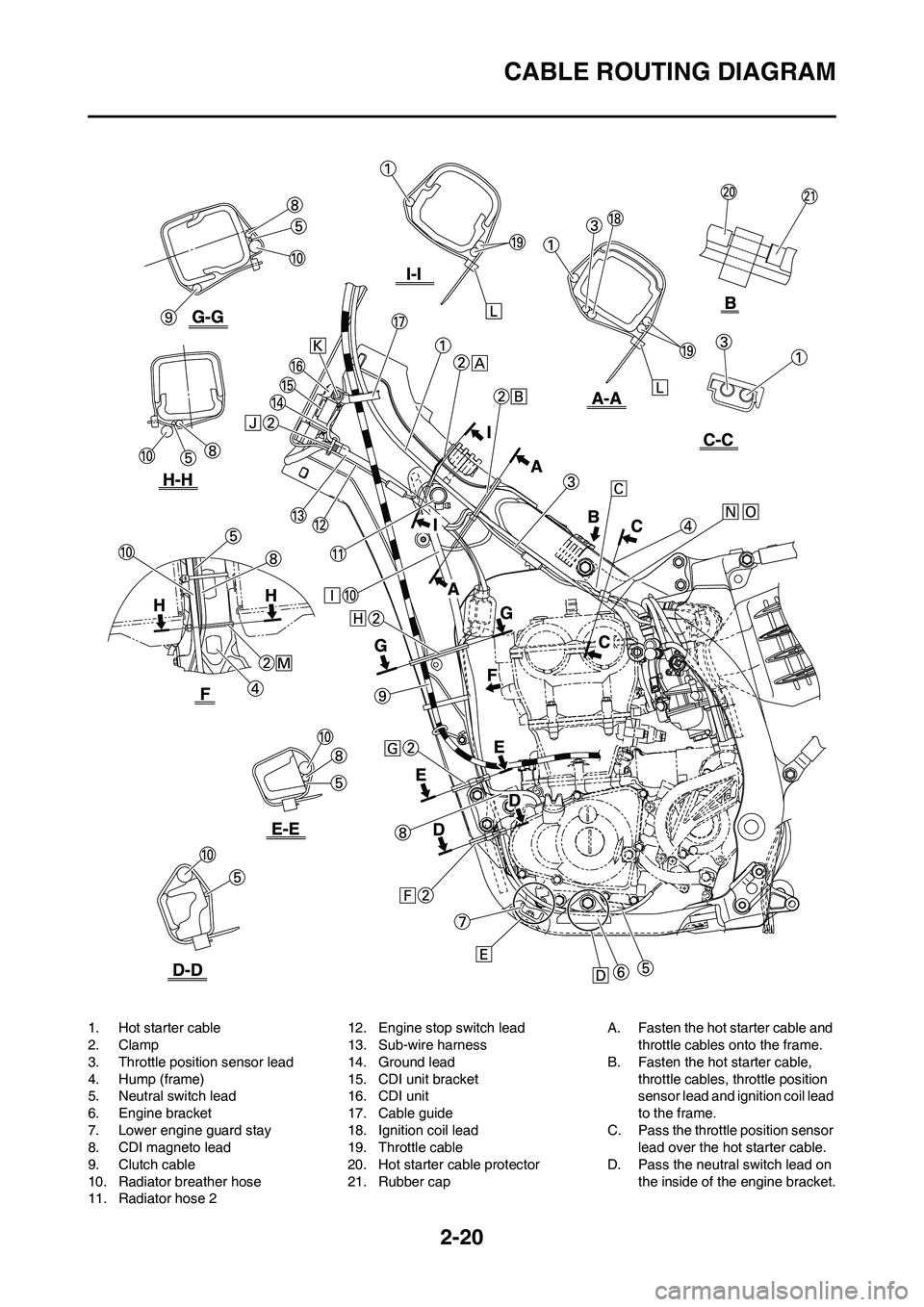
CABLE ROUTING DIAGRAM
1. Hot starter cable
2. Clamp
3. Throttle position sensor lead
4. Hump (frame)
5. Neutral switch lead
6. Engine bracket
7. Lower engine guard stay
8. CDI magneto lead
9. Clutch cable
10. Radiator breather hose
11. Radiator hose 212. Engine stop switch lead
13. Sub-wire harness
14. Ground lead
15. CDI unit bracket
16. CDI unit
17. Cable guide
18. Ignition coil lead
19. Throttle cable
20. Hot starter cable protector
21. Rubber capA. Fasten the hot starter cable and
throttle cables onto the frame.
B. Fasten the hot starter cable,
throttle cables, throttle position
sensor lead and ignition coil lead
to the frame.
C. Pass the throttle position sensor
lead over the hot starter cable.
D. Pass the neutral switch lead on
the inside of the engine bracket.
Page 77 of 190

4-7
CARBURETOR
CARBURETOR
REMOVING THE CARBURETOR
Order Part name Q'ty Remarks
Seat and fuel tank Refer to "SEAT, FUEL TANK AND SIDE
COVERS" section.
Rear shock absorber Refer to "REAR SHOCK ABSORBER" sec-
tion in the CHAPTER 5.
1Clamp 1
2 Throttle position sensor lead coupler 1
3 Throttle cable cover 1
4 Throttle cable 2
5 Clamp (air filter joint) 1 Loosen the screw (air filter joint).
6 Clamp (carburetor joint) 1 Loosen the screws (carburetor joint).
7 Hot starter plunger 1
8 Carburetor assembly 1
9 Carburetor joint 1
Page 80 of 190
4-10
CARBURETOR
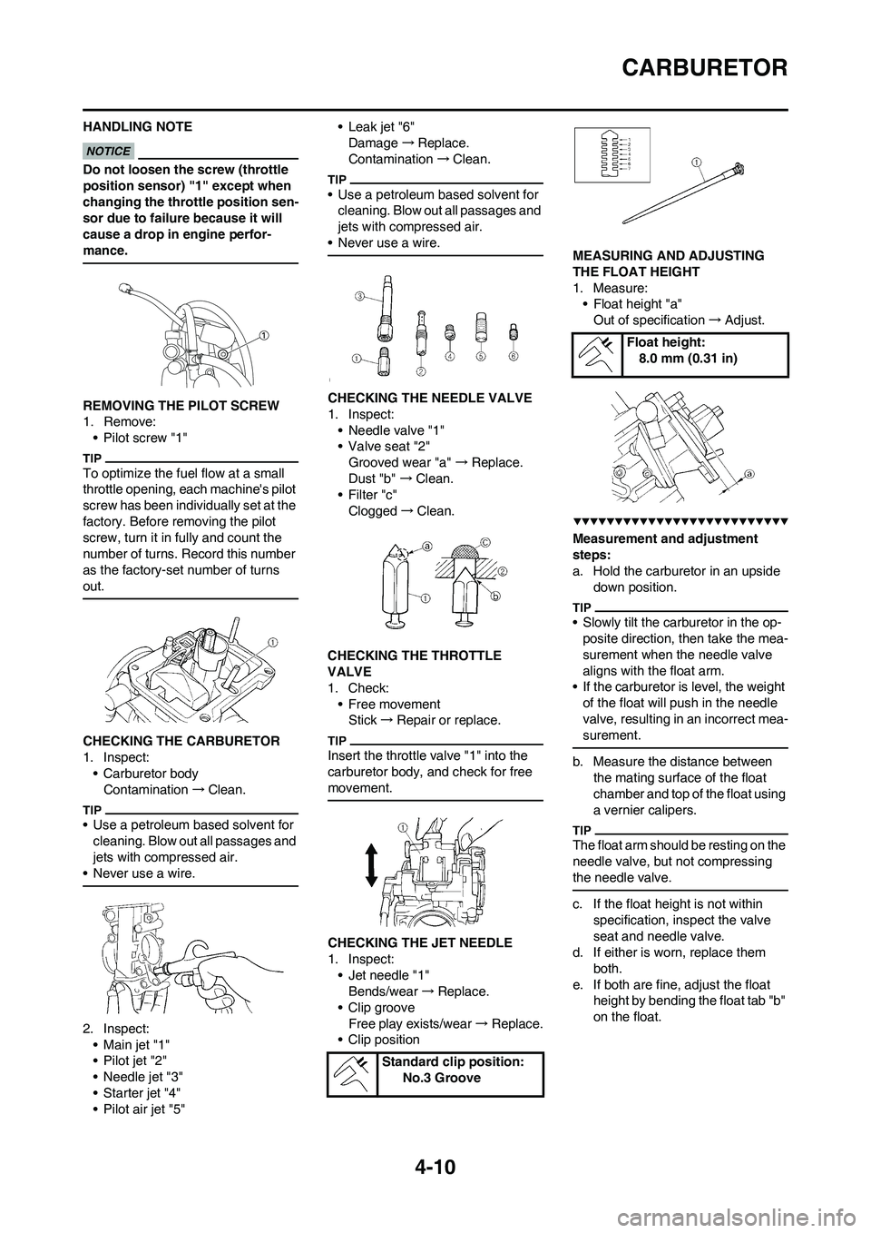
HANDLING NOTE
Do not loosen the screw (throttle
position sensor) "1" except when
changing the throttle position sen-
sor due to failure because it will
cause a drop in engine perfor-
mance.
REMOVING THE PILOT SCREW
1. Remove:
• Pilot screw "1"
To optimize the fuel flow at a small
throttle opening, each machine's pilot
screw has been individually set at the
factory. Before removing the pilot
screw, turn it in fully and count the
number of turns. Record this number
as the factory-set number of turns
out.
CHECKING THE CARBURETOR
1. Inspect:
• Carburetor body
Contamination→Clean.
• Use a petroleum based solvent for
cleaning. Blow out all passages and
jets with compressed air.
• Never use a wire.
2. Inspect:
•Main jet "1"
• Pilot jet "2"
• Needle jet "3"
• Starter jet "4"
• Pilot air jet "5"•Leak jet "6"
Damage→Replace.
Contamination→Clean.
• Use a petroleum based solvent for
cleaning. Blow out all passages and
jets with compressed air.
• Never use a wire.
CHECKING THE NEEDLE VALVE
1. Inspect:
• Needle valve "1"
• Valve seat "2"
Grooved wear "a" →Replace.
Dust "b" →Clean.
•Filter "c"
Clogged→Clean.
CHECKING THE THROTTLE
VALVE
1. Check:
• Free movement
Stick→Repair or replace.
Insert the throttle valve "1" into the
carburetor body, and check for free
movement.
CHECKING THE JET NEEDLE
1. Inspect:
• Jet needle "1"
Bends/wear→Replace.
• Clip groove
Free play exists/wear→Replace.
• Clip positionMEASURING AND ADJUSTING
THE FLOAT HEIGHT
1. Measure:
• Float height "a"
Out of specification→Adjust.
Measurement and adjustment
steps:
a. Hold the carburetor in an upside
down position.
• Slowly tilt the carburetor in the op-
posite direction, then take the mea-
surement when the needle valve
aligns with the float arm.
• If the carburetor is level, the weight
of the float will push in the needle
valve, resulting in an incorrect mea-
surement.
b. Measure the distance between
the mating surface of the float
chamber and top of the float using
a vernier calipers.
The float arm should be resting on the
needle valve, but not compressing
the needle valve.
c. If the float height is not within
specification, inspect the valve
seat and needle valve.
d. If either is worn, replace them
both.
e. If both are fine, adjust the float
height by bending the float tab "b"
on the float.
Standard clip position:
No.3 Groove
Float height:
8.0 mm (0.31 in)
Page 81 of 190

4-11
CARBURETOR
f. Recheck the float height.
CHECKING THE FLOAT
1. Inspect:
•Float "1"
Damage→Replace.
CHECKING THE STARTER
PLUNGER
1. Inspect:
• Cold starter plunger "1"
• Hot starter plunger "2"
Wear/damage→Replace.
CHECKING THE ACCELERATOR
PUMP
1. Inspect:
• Diaphragm (accelerator pump)
"1"
• Spring (accelerator pump) "2"
• Accelerator pump cover "3"
• O-ring "4"
• Push rod "5"
Tears (diaphragm)/damage→Re-
place.
Dirt→Clean.
2. Inspect:
• Throttle shaft "1"
• Spring "2"
• Lever 1 "3"
• Spring 1 "4"
• Lever 2 "5"• Spring 2 "6"
Dirt→Clean.
ASSEMBLING THE CARBURETOR
1. Install:
• Cold starter plunger "1"
2. Install:
• Pilot air jet "1"
3. Install:
• Spring 1 "1"
• Lever 1 "2"
To lever 2 "3".
Make sure the spring 1 fits on the
stopper "a" of the lever 2.
4. Install:
• Spring 2 "1"
To lever 2 "2".5. Install:
• Push rod link lever assembly "1"
Make sure the stopper "a" of the
spring 2 fits into the recess "b" in the
carburetor.
6. Install:
• Washer "1"
•Circlip "2"
7. Install:
• Spring "1"
To throttle shaft "2".
Install the bigger hook "a" of the
spring fits on the stopper "b" of the
throttle shaft pulley.
8. Install:
• Throttle shaft assembly "1"
• Washer (metal) "2"
• Washer (resin) "3"
• Valve lever "4"
• Apply the fluorochemical grease on
the bearings.
• Fit the projection "a" on the throttle
shaft assembly into the slot "b" in
the throttle position sensor.
• Make sure the stopper "c" of the
spring fits into the recess in the car-
buretor.
• Turn the throttle shaft assembly left
while holding down the lever 1 "5"
and fit the throttle stop screw tip "d"
to the stopper "e" of the throttle
shaft assembly pulley.
Page 83 of 190
4-13
CARBURETOR
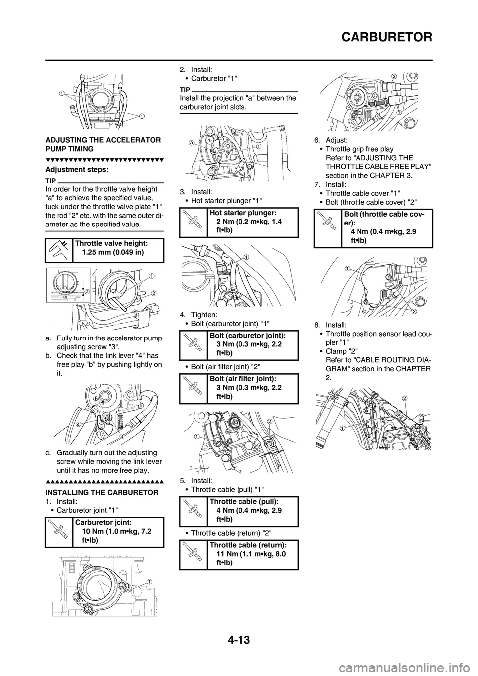
ADJUSTING THE ACCELERATOR
PUMP TIMING
Adjustment steps:
In order for the throttle valve height
"a" to achieve the specified value,
tuck under the throttle valve plate "1"
the rod "2" etc. with the same outer di-
ameter as the specified value.
a. Fully turn in the accelerator pump
adjusting screw "3".
b. Check that the link lever "4" has
free play "b" by pushing lightly on
it.
c. Gradually turn out the adjusting
screw while moving the link lever
until it has no more free play.
INSTALLING THE CARBURETOR
1. Install:
• Carburetor joint "1"2. Install:
• Carburetor "1"
Install the projection "a" between the
carburetor joint slots.
3. Install:
• Hot starter plunger "1"
4. Tighten:
• Bolt (carburetor joint) "1"
• Bolt (air filter joint) "2"
5. Install:
• Throttle cable (pull) "1"
• Throttle cable (return) "2"6. Adjust:
• Throttle grip free play
Refer to "ADJUSTING THE
THROTTLE CABLE FREE PLAY"
section in the CHAPTER 3.
7. Install:
• Throttle cable cover "1"
• Bolt (throttle cable cover) "2"
8. Install:
• Throttle position sensor lead cou-
pler "1"
•Clamp "2"
Refer to "CABLE ROUTING DIA-
GRAM" section in the CHAPTER
2. Throttle valve height:
1.25 mm (0.049 in)
Carburetor joint:
10 Nm (1.0 m•kg, 7.2
ft•lb)
Hot starter plunger:
2 Nm (0.2 m•kg, 1.4
ft•lb)
Bolt (carburetor joint):
3 Nm (0.3 m•kg, 2.2
ft•lb)
Bolt (air filter joint):
3 Nm (0.3 m•kg, 2.2
ft•lb)
Throttle cable (pull):
4 Nm (0.4 m•kg, 2.9
ft•lb)
Throttle cable (return):
11 Nm (1.1 m•kg, 8.0
ft•lb)Bolt (throttle cable cov-
er):
4 Nm (0.4 m•kg, 2.9
ft•lb)
Page 172 of 190

6-2
ELECTRICAL COMPONENTS AND WIRING DIAGRAM
ELECTRICAL
COMPONENTS AND
WIRING DIAGRAM
ELECTRICAL COMPONENTS
1. Engine stop switch
2. Throttle position sensor
3. Neutral switch4. CDI magneto
5. Ignition coil
6. Spark plug7. CDI unit
WIRING DIAGRAM
1. Engine stop switch
2. Throttle position sensor
3. Neutral switch
4. CDI magneto
5. Ignition coil
6. Spark plug
7. CDI unitCOLOR CODE
BBlack
Br Brown
GGreen
LBlue
OOrange
PPink
RRed
Sb Sky blue
WWhite
Y YellowB/L Black/Blue
B/W Black/White
B/Y Black/Yellow
G/B Green/Black
L/W Blue/White
R/W Red/White
B/WB/W
B/L
B/Y
SbSb
G/B
LYLY
P
B
B
B
B
G
O
WR
P
GW
R P
B Br W
W
B/Y GBr
G RR
OB Sb Sb Y
Y
WY
W
GG
B
PP
Br BrR R
OL
B SbY LL
B/L B/W B/WG/B
B B
B/L L Sb
B/L
G/B
G/BB/Y
B/Y
B/W
O B/W
BrBrP
Page 176 of 190

6-6
THROTTLE POSITION SENSOR SYSTEM
THROTTLE POSITION SENSOR SYSTEM
INSPECTION STEPS
If the throttle position sensor will not operate, use the following inspection steps.
*marked: Refer to "IGNITION SYSTEM" section.
Use the following special tools in this inspection.
Check entire ignition system for connection. No good→Repair or replace.
OK↓
Check throttle position sensor. (Throttle position
sensor coil)No good→
Replace.
OK↓
*Check CDI magneto. (Charging coil) No good→Replace.
OK↓
Check CDI unit. (Throttle position sensor input
voltage)No good→
Replace.
Pocket tester:
YU-3112-C/90890-03112