engine coolant YAMAHA YZ450F 2010 User Guide
[x] Cancel search | Manufacturer: YAMAHA, Model Year: 2010, Model line: YZ450F, Model: YAMAHA YZ450F 2010Pages: 230, PDF Size: 14.09 MB
Page 112 of 230
4-31
OIL FILTER ELEMENT AND WATER PUMP
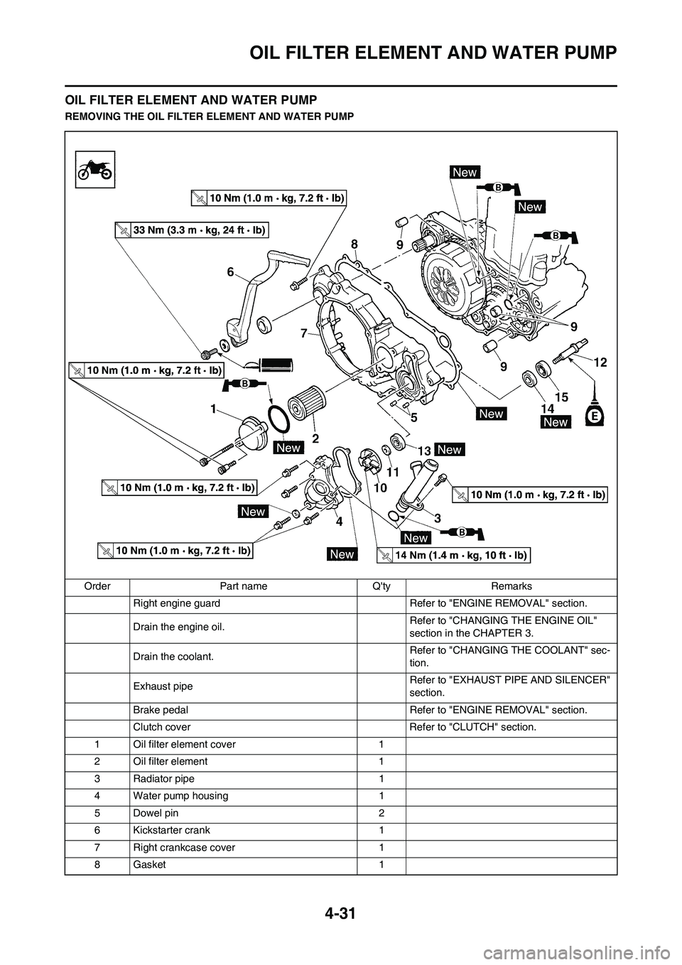
OIL FILTER ELEMENT AND WATER PUMP
REMOVING THE OIL FILTER ELEMENT AND WATER PUMP
Order Part name Q'ty Remarks
Right engine guard Refer to "ENGINE REMOVAL" section.
Drain the engine oil. Refer to "CHANGING THE ENGINE OIL"
section in the CHAPTER 3.
Drain the coolant. Refer to "CHANGING THE COOLANT" sec-
tion.
Exhaust pipe Refer to "EXHAUST PIPE AND SILENCER"
section.
Brake pedal Refer to "ENGINE REMOVAL" section.
Clutch cover Refer to "CLUTCH" section.
1 Oil filter element cover 1
2 Oil filter element 1
3 Radiator pipe 1
4 Water pump housing 1
5 Dowel pin 2
6 Kickstarter crank 1
7 Right crankcase cover 1
8 Gasket 1
Page 114 of 230
4-33
OIL FILTER ELEMENT AND WATER PUMP
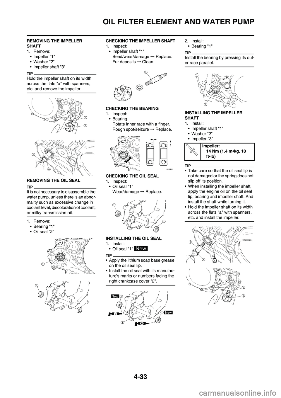
REMOVING THE IMPELLER
SHAFT
1. Remove:
• Impeller "1"
• Washer "2"
• Impeller shaft "3"
Hold the impeller shaft on its width
across the flats "a" with spanners,
etc. and remove the impeller.
REMOVING THE OIL SEAL
It is not necessary to disassemble the
water pump, unless there is an abnor-
mality such as excessive change in
coolant level, discoloration of coolant,
or milky transmission oil.
1. Remove:
• Bearing "1"
• Oil seal "2"CHECKING THE IMPELLER SHAFT
1. Inspect:
• Impeller shaft "1"
Bend/wear/damage→Replace.
Fur deposits→Clean.
CHECKING THE BEARING
1. Inspect:
•Bearing
Rotate inner race with a finger.
Rough spot/seizure→Replace.
CHECKING THE OIL SEAL
1. Inspect:
• Oil seal "1"
Wear/damage→Replace.
INSTALLING THE OIL SEAL
1. Install:
• Oil seal "1"
• Apply the lithium soap base grease
on the oil seal lip.
• Install the oil seal with its manufac-
ture's marks or numbers facing the
right crankcase cover "2".
2. Install:
• Bearing "1"
Install the bearing by pressing its out-
er race parallel.
INSTALLING THE IMPELLER
SHAFT
1. Install:
• Impeller shaft "1"
• Washer "2"
• Impeller "3"
• Take care so that the oil seal lip is
not damaged or the spring does not
slip off its position.
• When installing the impeller shaft,
apply the engine oil on the oil seal
lip, bearing and impeller shaft. And
install the shaft while turning it.
• Hold the impeller shaft on its width
across the flats "a" with spanners,
etc. and install the impeller.
Impeller:
14 Nm (1.4 m•kg, 10
ft•lb)
Page 115 of 230
4-34
OIL FILTER ELEMENT AND WATER PUMP
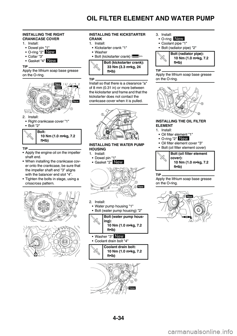
INSTALLING THE RIGHT
CRANKCASE COVER
1. Install:
• Dowel pin "1"
• O-ring "2"
•Collar "3"
• Gasket "4"
Apply the lithium soap base grease
on the O-ring.
2. Install:
• Right crankcase cover "1"
•Bolt "2"
• Apply the engine oil on the impeller
shaft end.
• When installing the crankcase cov-
er onto the crankcase, be sure that
the impeller shaft end "3" aligns
with the balancer end slot "4".
• Tighten the bolts in stage, using a
crisscross pattern.
INSTALLING THE KICKSTARTER
CRANK
1. Install:
• Kickstarter crank "1"
• Washer
• Bolt (kickstarter crank)
Install so that there is a clearance "a"
of 8 mm (0.31 in) or more between
the kickstarter and frame and that the
kickstarter does not contact the
crankcase cover when it is pulled.
INSTALLING THE WATER PUMP
HOUSING
1. Install:
• Dowel pin "1"
• Gasket "2"
2. Install:
• Water pump housing "1"
• Bolt (water pump housing) "2"
• Washer "3"
• Coolant drain bolt "4"3. Install:
• O-ring
• Coolant pipe "1"
• Bolt (radiator pipe) "2"
Apply the lithium soap base grease
on the O-ring.
INSTALLING THE OIL FILTER
ELEMENT
1. Install:
• Oil filter element "1"
• O-ring "2"
• Oil filter element cover "3"
• Bolt (oil filter element cover)
Apply the lithium soap base grease
on the O-ring.
Bolt:
10 Nm (1.0 m•kg, 7.2
ft•lb)
Bolt (kickstarter crank):
33 Nm (3.3 m•kg, 24
ft•lb)
Bolt (water pump hous-
ing):
10 Nm (1.0 m•kg, 7.2
ft•lb)
Coolant drain bolt:
10 Nm (1.0 m•kg, 7.2
ft•lb)
Bolt (radiator pipe):
10 Nm (1.0 m•kg, 7.2
ft•lb)
Bolt (oil filter element
cover):
10 Nm (1.0 m•kg, 7.2
ft•lb)
Page 128 of 230
4-47
ENGINE REMOVAL
ENGINE REMOVAL
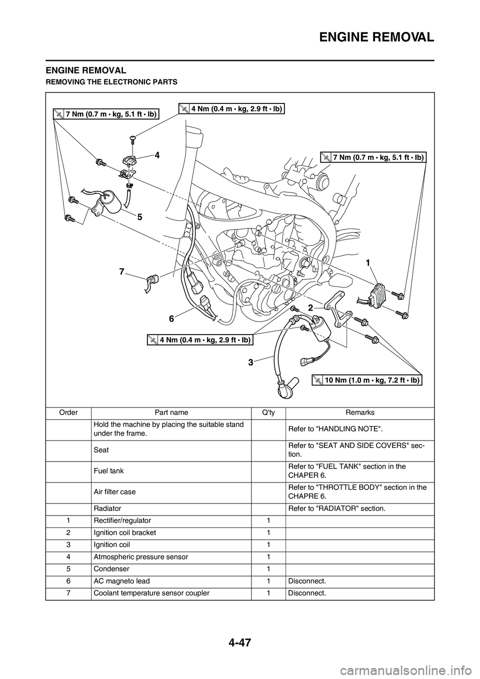
REMOVING THE ELECTRONIC PARTS
Order Part name Q'ty Remarks
Hold the machine by placing the suitable stand
under the frame.Refer to "HANDLING NOTE".
SeatRefer to "SEAT AND SIDE COVERS" sec-
tion.
Fuel tankRefer to "FUEL TANK" section in the
CHAPER 6.
Air filter caseRefer to "THROTTLE BODY" section in the
CHAPRE 6.
Radiator Refer to "RADIATOR" section.
1 Rectifier/regulator 1
2 Ignition coil bracket 1
3 Ignition coil 1
4 Atmospheric pressure sensor 1
5 Condenser 1
6 AC magneto lead 1 Disconnect.
7 Coolant temperature sensor coupler 1 Disconnect.
Page 187 of 230
7-1
ELECTRICAL COMPONENTS AND WIRING DIAGRAM
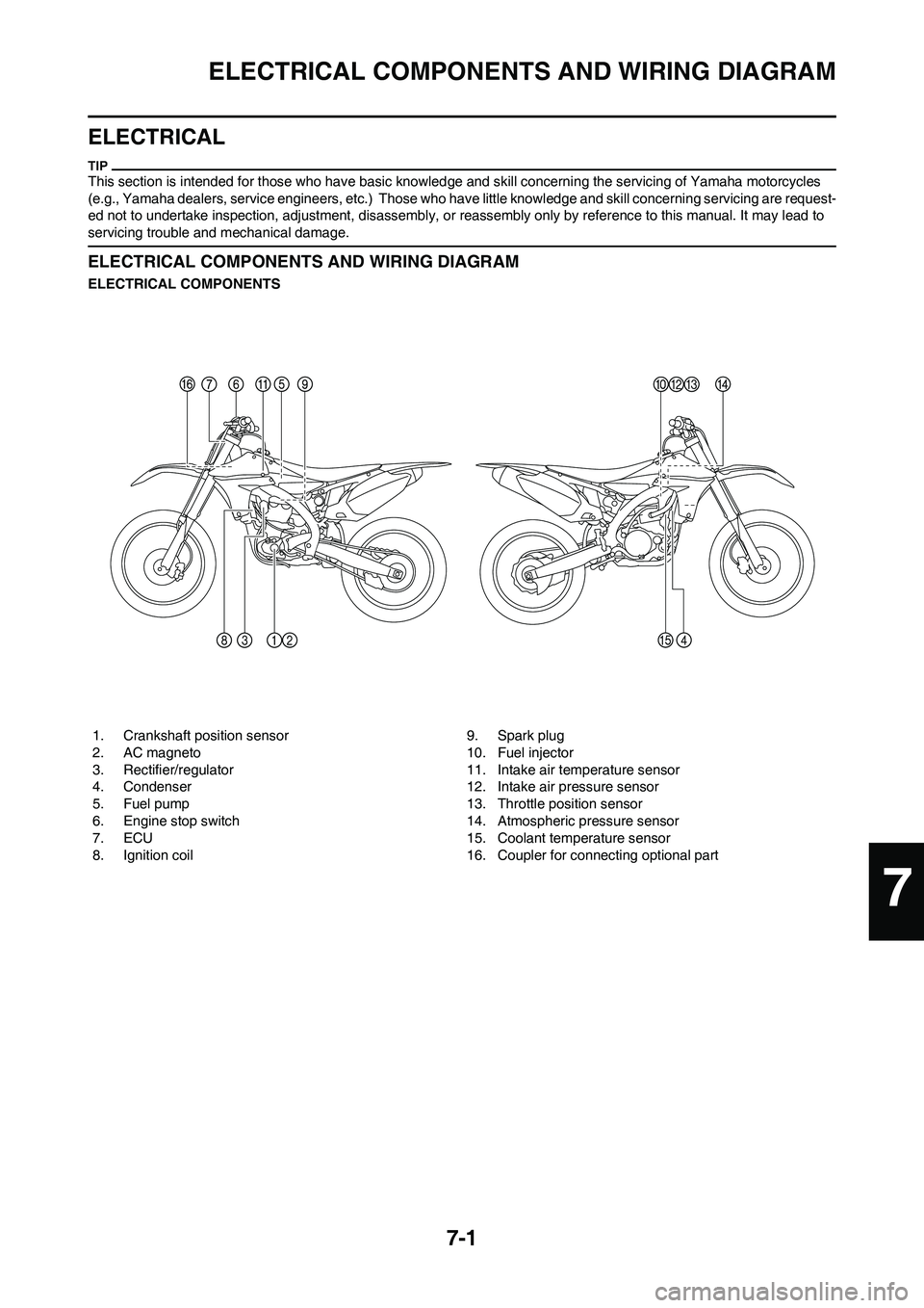
ELECTRICAL
This section is intended for those who have basic knowledge and skill concerning the servicing of Yamaha motorcycles
(e.g., Yamaha dealers, service engineers, etc.) Those who have little knowledge and skill concerning servicing are request-
ed not to undertake inspection, adjustment, disassembly, or reassembly only by reference to this manual. It may lead to
servicing trouble and mechanical damage.
ELECTRICAL COMPONENTS AND WIRING DIAGRAM
ELECTRICAL COMPONENTS
1. Crankshaft position sensor
2. AC magneto
3. Rectifier/regulator
4. Condenser
5. Fuel pump
6. Engine stop switch
7. ECU
8. Ignition coil9. Spark plug
10. Fuel injector
11. Intake air temperature sensor
12. Intake air pressure sensor
13. Throttle position sensor
14. Atmospheric pressure sensor
15. Coolant temperature sensor
16. Coupler for connecting optional part
7
Page 188 of 230
7-2
ELECTRICAL COMPONENTS AND WIRING DIAGRAM
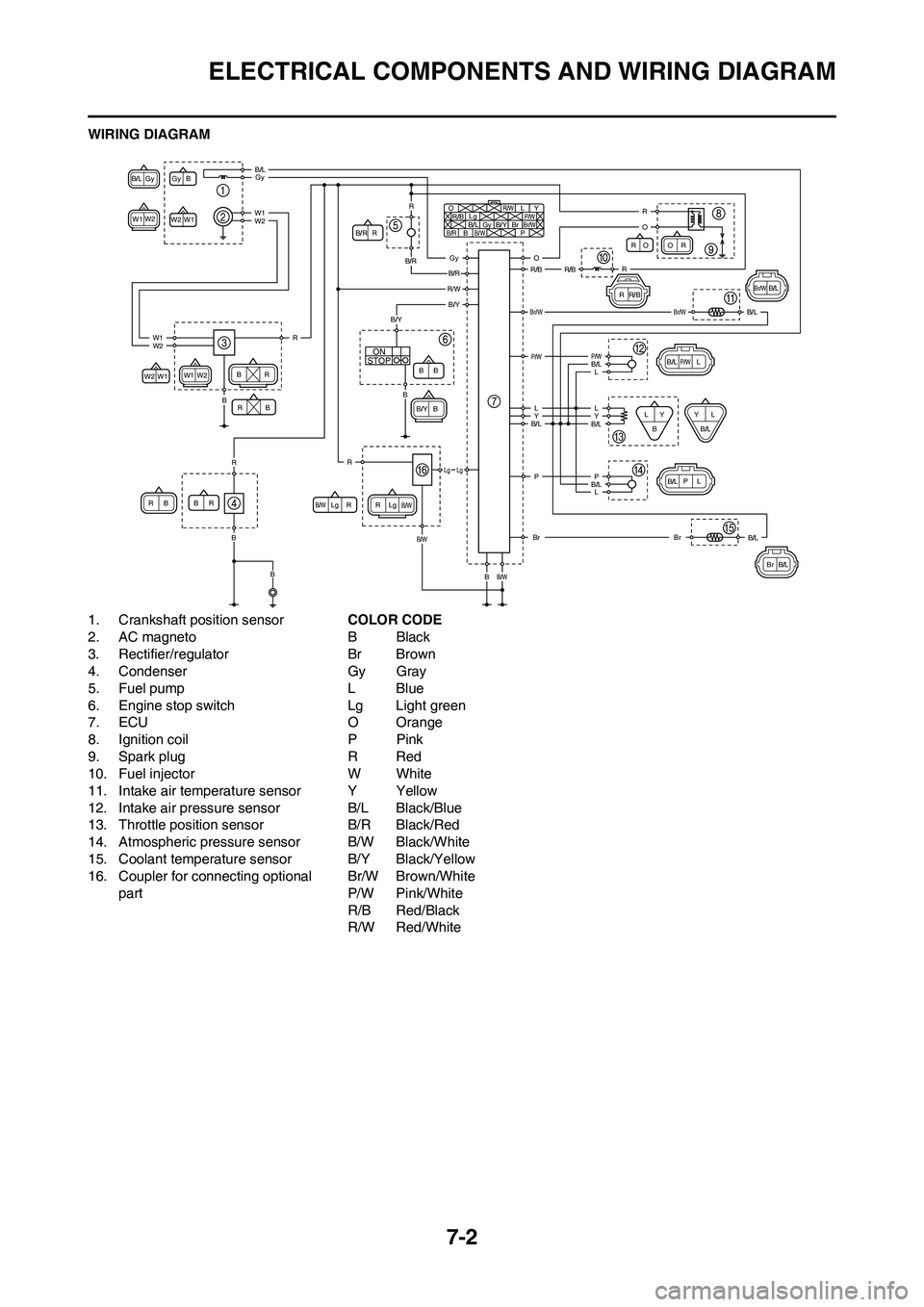
WIRING DIAGRAM
1. Crankshaft position sensor
2. AC magneto
3. Rectifier/regulator
4. Condenser
5. Fuel pump
6. Engine stop switch
7. ECU
8. Ignition coil
9. Spark plug
10. Fuel injector
11. Intake air temperature sensor
12. Intake air pressure sensor
13. Throttle position sensor
14. Atmospheric pressure sensor
15. Coolant temperature sensor
16. Coupler for connecting optional part COLOR CODE
BBlack
Br Brown
Gy Gray
LBlue
Lg Light green
O Orange
PPink
RRed
WWhite
YYellow
B/L Black/Blue
B/R Black/Red
B/W Black/White
B/Y Black/Yellow
Br/W Brown/White
P/W Pink/White
R/B Red/Black
R/W Red/White
STOPON
Gy
Gy
B
B
/L
W1
W2
W2 O
R /B
R RR
R
R
R R
Lg
Lg Lg L
P
/W
P YB
/RB
B B
B
B BB
BB/W
B /W
B/W Br
/WGy
B /L
W1 W1
W2 W2 B
/Y
B /Y Br
B /R
R /W
OO
R /B
RR
R
L
P/W
P YL
L
LY
Br /WB /L
B /L
B/L
B
B/L
B/L
Br
W1
Br
/W
W2
R
R O
B/L
L
Y
B /L
Br
R
P
Gy
Gy
B /R
B
/R
R/WB /Y
B
/L
W1
W2
W1 R
R R
B
B
/Y
Lg Lg
O
R /B
R/B
Br /W
P /W P
/W
L L
Y
B /L B
/L
B/L
Br
B
B /W
B
/W
B
B
B L
B
/L
P
Page 197 of 230
7-11
FUEL INJECTION SYSTEM
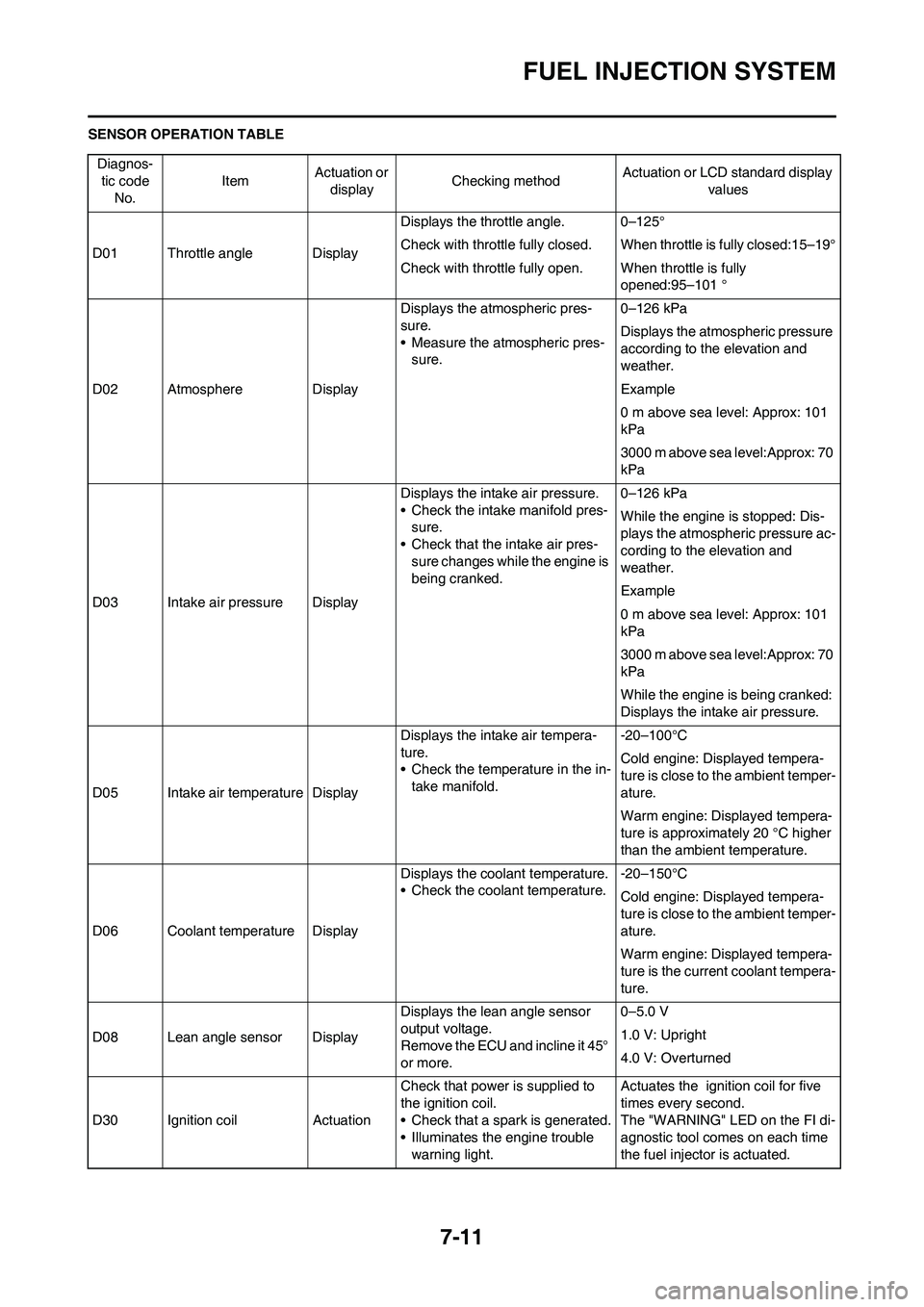
SENSOR OPERATION TABLE
Diagnos-
tic code
No.ItemActuation or
displayChecking methodActuation or LCD standard display
values
D01 Throttle angle DisplayDisplays the throttle angle. 0–125°
Check with throttle fully closed. When throttle is fully closed:15–19°
Check with throttle fully open. When throttle is fully
opened:95–101 °
D02 Atmosphere DisplayDisplays the atmospheric pres-
sure.
• Measure the atmospheric pres-
sure.0–126 kPa
Displays the atmospheric pressure
according to the elevation and
weather.
Example
0 m above sea level: Approx: 101
kPa
3000 m above sea level:Approx: 70
kPa
D03 Intake air pressure DisplayDisplays the intake air pressure.
• Check the intake manifold pres-
sure.
• Check that the intake air pres-
sure changes while the engine is
being cranked.0–126 kPa
While the engine is stopped: Dis-
plays the atmospheric pressure ac-
cording to the elevation and
weather.
Example
0 m above sea level: Approx: 101
kPa
3000 m above sea level:Approx: 70
kPa
While the engine is being cranked:
Displays the intake air pressure.
D05 Intake air temperature DisplayDisplays the intake air tempera-
ture.
• Check the temperature in the in-
take manifold.-20–100°C
Cold engine: Displayed tempera-
ture is close to the ambient temper-
ature.
Warm engine: Displayed tempera-
ture is approximately 20 °C higher
than the ambient temperature.
D06 Coolant temperature DisplayDisplays the coolant temperature.
• Check the coolant temperature.-20–150°C
Cold engine: Displayed tempera-
ture is close to the ambient temper-
ature.
Warm engine: Displayed tempera-
ture is the current coolant tempera-
ture.
D08 Lean angle sensor DisplayDisplays the lean angle sensor
output voltage.
Remove the ECU and incline it 45°
or more.0–5.0 V
1.0 V: Upright
4.0 V: Overturned
D30 Ignition coil ActuationCheck that power is supplied to
the ignition coil.
• Check that a spark is generated.
• Illuminates the engine trouble
warning light.Actuates the ignition coil for five
times every second.
The "WARNING" LED on the FI di-
agnostic tool comes on each time
the fuel injector is actuated.
Page 206 of 230
7-20
FUEL INJECTION SYSTEM
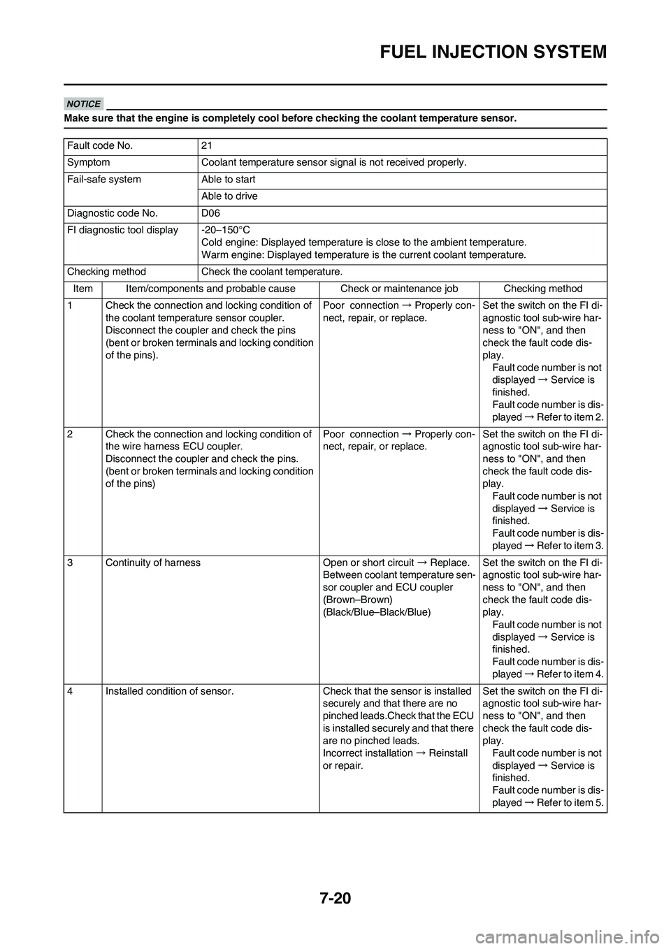
Make sure that the engine is completely cool before checking the coolant temperature sensor.
Fault code No. 21
Symptom Coolant temperature sensor signal is not received properly.
Fail-safe system Able to start
Able to drive
Diagnostic code No. D06
FI diagnostic tool display -20–150°C
Cold engine: Displayed temperature is close to the ambient temperature.
Warm engine: Displayed temperature is the current coolant temperature.
Checking method Check the coolant temperature.
Item Item/components and probable cause Check or maintenance job Checking method
1 Check the connection and locking condition of
the coolant temperature sensor coupler.
Disconnect the coupler and check the pins
(bent or broken terminals and locking condition
of the pins).Poor connection → Properly con-
nect, repair, or replace.Set the switch on the FI di-
agnostic tool sub-wire har-
ness to "ON", and then
check the fault code dis-
play.
Fault code number is not
displayed → Service is
finished.
Fault code number is dis-
played → Refer to item 2.
2 Check the connection and locking condition of
the wire harness ECU coupler.
Disconnect the coupler and check the pins.
(bent or broken terminals and locking condition
of the pins)Poor connection → Properly con-
nect, repair, or replace.Set the switch on the FI di-
agnostic tool sub-wire har-
ness to "ON", and then
check the fault code dis-
play.
Fault code number is not
displayed → Service is
finished.
Fault code number is dis-
played → Refer to item 3.
3 Continuity of harness Open or short circuit → Replace.
Between coolant temperature sen-
sor coupler and ECU coupler
(Brown–Brown)
(Black/Blue–Black/Blue)Set the switch on the FI di-
agnostic tool sub-wire har-
ness to "ON", and then
check the fault code dis-
play.
Fault code number is not
displayed → Service is
finished.
Fault code number is dis-
played → Refer to item 4.
4 Installed condition of sensor. Check that the sensor is installed
securely and that there are no
pinched leads.Check that the ECU
is installed securely and that there
are no pinched leads.
Incorrect installation → Reinstall
or repair.Set the switch on the FI di-
agnostic tool sub-wire har-
ness to "ON", and then
check the fault code dis-
play.
Fault code number is not
displayed → Service is
finished.
Fault code number is dis-
played → Refer to item 5.
Page 207 of 230
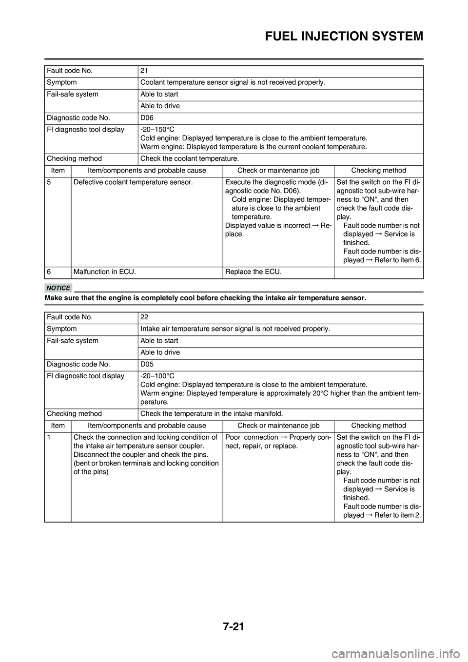
7-21
FUEL INJECTION SYSTEM
Make sure that the engine is completely cool before checking the intake air temperature sensor.
5 Defective coolant temperature sensor. Execute the diagnostic mode (di-
agnostic code No. D06).
Cold engine: Displayed temper-
ature is close to the ambient
temperature.
Displayed value is incorrect → Re-
place. Set the switch on the FI di-
agnostic tool sub-wire har-
ness to "ON", and then
check the fault code dis-
play.
Fault code number is not
displayed → Service is
finished.
Fault code number is dis-
played → Refer to item 6.
6 Malfunction in ECU. Replace the ECU.
Fault code No. 22
Symptom Intake air temperature sensor signal is not received properly.
Fail-safe system Able to start Able to drive
Diagnostic code No. D05
FI diagnostic tool display -20–100°C Cold engine: Displayed temperature is close to the ambient temperature.
Warm engine: Displayed temperature is approx imately 20°C higher than the ambient tem-
perature.
Checking method Check the temperature in the intake manifold. Item Item/components and probable cause Check or maintenance job Checking method
1 Check the connection and locking condition of the intake air temperature sensor coupler.
Disconnect the coupler and check the pins.
(bent or broken terminals and locking condition
of the pins) Poor connection
→ Properly con-
nect, repair, or replace. Set the switch on the FI di-
agnostic tool sub-wire har-
ness to "ON", and then
check the fault code dis-
play.
Fault code number is not
displayed → Service is
finished.
Fault code number is dis-
played → Refer to item 2.
Fault code No. 21
Symptom Coolant temperature sensor signal is not received properly.
Fail-safe system Able to start
Able to drive
Diagnostic code No. D06
FI diagnostic tool display -20–150°C Cold engine: Displayed temperature is close to the ambient temperature.
Warm engine: Displayed temperature is the current coolant temperature.
Checking method Check the coolant temperature. Item Item/components and probable cause Check or maintenance job Checking method