oil filter YAMAHA YZ450F 2010 User Guide
[x] Cancel search | Manufacturer: YAMAHA, Model Year: 2010, Model line: YZ450F, Model: YAMAHA YZ450F 2010Pages: 230, PDF Size: 14.09 MB
Page 66 of 230
3-10
ENGINE
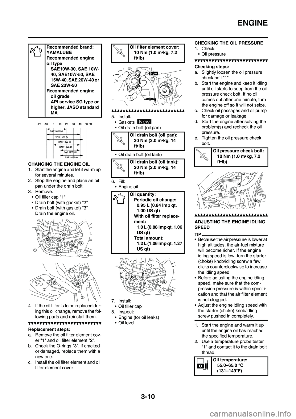
CHANGING THE ENGINE OIL
1. Start the engine and let it warm up for several minutes.
2. Stop the engine and place an oil pan under the drain bolt.
3. Remove: • Oil filler cap "1"
• Drain bolt (with gasket) "2"
• Drain bolt (with gasket) "3"Drain the engine oil.
4. If the oil filter is to be replaced dur- ing this oil change, remove the fol-
lowing parts and reinstall them.
Replacement steps:
a. Remove the oil filter element cov-er "1" and oil filter element "2".
b. Check the O-rings "3", if cracked or damaged, replace them with a
new one.
c. Install the oil filter element and oil filter element cover.
5. Install:• Gaskets
• Oil drain bolt (oil pan)
• Oil drain bolt (oil tank)
6. Fill: • Engine oil
7. Install: • Oil filler cap
8. Inspect:
• Engine (for oil leaks)
• Oil level CHECKING THE OIL PRESSURE
1. Check:
• Oil pressure
Checking steps:
a. Slightly loosen the oil pressure check bolt "1".
b. Start the engine and keep it idling until oil starts to seep from the oil
pressure check bolt. If no oil
comes out after one minute, turn
the engine off so it will not seize.
c. Check oil passages and oil pump
for damage or leakage.
d. Start the engine after solving the problem(s) and recheck the oil
pressure.
e. Tighten the oil pressure check bolt.
ADJUSTING THE ENGINE IDLING
SPEED
• Because the air pressure is lower at
high altitudes, the air-fuel mixture
will become richer. If the engine
idling speed is low, turn the starter
(choke) knob/idling screw a few
clicks counterclockwise to increase
the idling speed.
• Before adjusting the engine idling speed, make sure that the com-
pression pressure is within specifi-
cation and that the air filter element
is not clogged.
• Adjust the engine idling speed with
the starter (choke) knob/idling
screw pushed in completely.
1. Start the engine and warm it up until the engine oil has reached
the specified temperature.
2. Use a temperature probe tester "1" and contact it to the drain bolt
thread.
Recommended brand:
YAMALUBE
Recommended engine
oil type
SAE10W-30, SAE 10W-
40, SAE10W-50, SAE
15W-40, SAE 20W-40 or
SAE 20W-50
Recommended engine
oil grade
API service SG type or
higher, JASO standard
MA
Oil filter element cover:10 Nm (1.0 m•kg, 7.2
ft•lb)
Oil drain bolt (oil pan): 20 Nm (2.0 m•kg, 14
ft•lb)
Oil drain bolt (oil tank): 20 Nm (2.0 m•kg, 14
ft•lb)
Oil quantity: Periodic oil change:0.95 L (0.84 Imp qt,
1.00 US qt)
With oil filter replace-
ment: 1.0 L (0.88 Imp qt, 1.06
US qt)
Total amount: 1.2 L (1.06 Imp qt, 1.27
US qt)
Oil pressure check bolt:
10 Nm (1.0 m•kg, 7.2
ft•lb)
Oil temperature: 55.0–65.0 °C
(131–149°F)
Page 81 of 230
3-25
ELECTRICAL
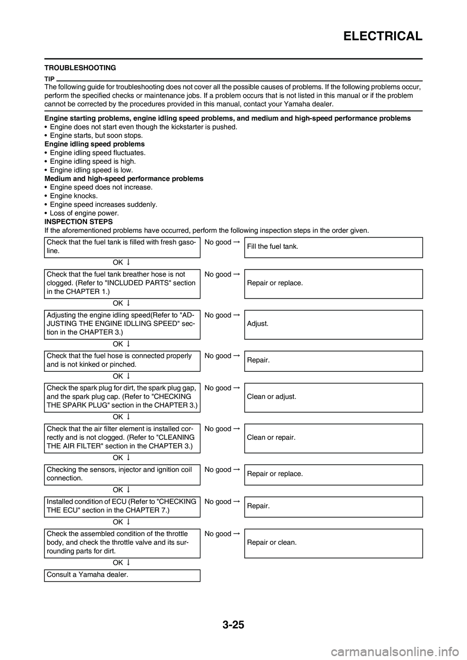
TROUBLESHOOTING
The following guide for troubleshooting does not cover all the possible causes of problems. If the following problems occur,
perform the specified checks or maintenance jobs. If a problem occurs that is not listed in this manual or if the problem
cannot be corrected by the procedures provided in this manual, contact your Yamaha dealer.
Engine starting problems, engine idling speed problems, and medium and high-speed performance problems
• Engine does not start even though the kickstarter is pushed.
• Engine starts, but soon stops.
Engine idling speed problems
• Engine idling speed fluctuates.
• Engine idling speed is high.
• Engine idling speed is low.
Medium and high-speed performance problems
• Engine speed does not increase.
• Engine knocks.
• Engine speed increases suddenly.
• Loss of engine power.
INSPECTION STEPS
If the aforementioned problems have occurred, perform the following inspection steps in the order given.
Check that the fuel tank is filled with fresh gaso-
line.No good→
Fill the fuel tank.
OK↓
Check that the fuel tank breather hose is not
clogged. (Refer to "INCLUDED PARTS" section
in the CHAPTER 1.)No good→
Repair or replace.
OK↓
Adjusting the engine idling speed(Refer to "AD-
JUSTING THE ENGINE IDLLING SPEED" sec-
tion in the CHAPTER 3.)No good→
Adjust.
OK↓
Check that the fuel hose is connected properly
and is not kinked or pinched.No good→
Repair.
OK↓
Check the spark plug for dirt, the spark plug gap,
and the spark plug cap. (Refer to "CHECKING
THE SPARK PLUG" section in the CHAPTER 3.)No good→
Clean or adjust.
OK↓
Check that the air filter element is installed cor-
rectly and is not clogged. (Refer to "CLEANING
THE AIR FILTER" section in the CHAPTER 3.)No good→
Clean or repair.
OK↓
Checking the sensors, injector and ignition coil
connection.No good→
Repair or replace.
OK↓
Installed condition of ECU (Refer to "CHECKING
THE ECU" section in the CHAPTER 7.)No good→
Repair.
OK↓
Check the assembled condition of the throttle
body, and check the throttle valve and its sur-
rounding parts for dirt.No good→
Repair or clean.
OK↓
Consult a Yamaha dealer.
Page 112 of 230
4-31
OIL FILTER ELEMENT AND WATER PUMP
OIL FILTER ELEMENT AND WATER PUMP
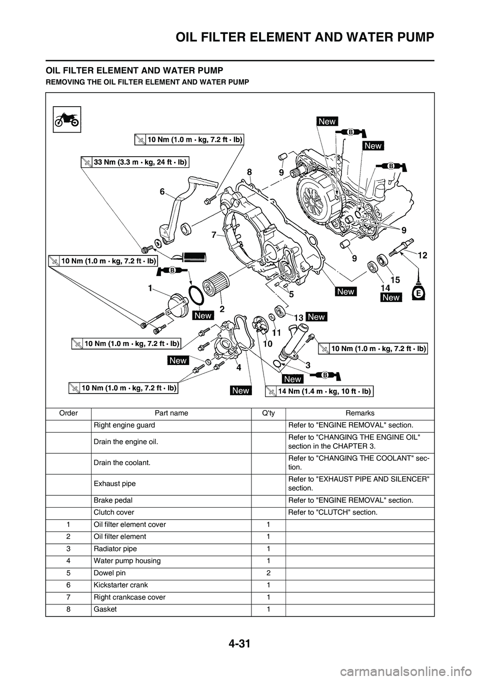
REMOVING THE OIL FILTER ELEMENT AND WATER PUMP
Order Part name Q'ty Remarks
Right engine guard Refer to "ENGINE REMOVAL" section.
Drain the engine oil. Refer to "CHANGING THE ENGINE OIL"
section in the CHAPTER 3.
Drain the coolant. Refer to "CHANGING THE COOLANT" sec-
tion.
Exhaust pipe Refer to "EXHAUST PIPE AND SILENCER"
section.
Brake pedal Refer to "ENGINE REMOVAL" section.
Clutch cover Refer to "CLUTCH" section.
1 Oil filter element cover 1
2 Oil filter element 1
3 Radiator pipe 1
4 Water pump housing 1
5 Dowel pin 2
6 Kickstarter crank 1
7 Right crankcase cover 1
8 Gasket 1
Page 113 of 230

4-32
OIL FILTER ELEMENT AND WATER PUMP
9 Dowel pin/O-ring 3/1
10 Impeller 1 Refer to removal section.
11 Washer 1 Refer to removal section.
12 Impeller shaft 1 Refer to removal section.
13 Oil seal 1 1 Refer to removal section.
14 Oil seal 2 1 Refer to removal section.
15 Bearing 1 Refer to removal section. Order Part name Q'ty Remarks
Page 114 of 230
4-33
OIL FILTER ELEMENT AND WATER PUMP
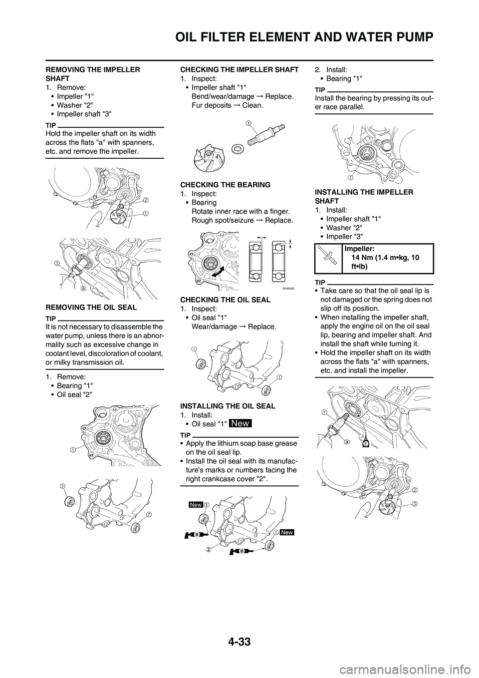
REMOVING THE IMPELLER
SHAFT
1. Remove:
• Impeller "1"
• Washer "2"
• Impeller shaft "3"
Hold the impeller shaft on its width
across the flats "a" with spanners,
etc. and remove the impeller.
REMOVING THE OIL SEAL
It is not necessary to disassemble the
water pump, unless there is an abnor-
mality such as excessive change in
coolant level, discoloration of coolant,
or milky transmission oil.
1. Remove:
• Bearing "1"
• Oil seal "2"CHECKING THE IMPELLER SHAFT
1. Inspect:
• Impeller shaft "1"
Bend/wear/damage→Replace.
Fur deposits→Clean.
CHECKING THE BEARING
1. Inspect:
•Bearing
Rotate inner race with a finger.
Rough spot/seizure→Replace.
CHECKING THE OIL SEAL
1. Inspect:
• Oil seal "1"
Wear/damage→Replace.
INSTALLING THE OIL SEAL
1. Install:
• Oil seal "1"
• Apply the lithium soap base grease
on the oil seal lip.
• Install the oil seal with its manufac-
ture's marks or numbers facing the
right crankcase cover "2".
2. Install:
• Bearing "1"
Install the bearing by pressing its out-
er race parallel.
INSTALLING THE IMPELLER
SHAFT
1. Install:
• Impeller shaft "1"
• Washer "2"
• Impeller "3"
• Take care so that the oil seal lip is
not damaged or the spring does not
slip off its position.
• When installing the impeller shaft,
apply the engine oil on the oil seal
lip, bearing and impeller shaft. And
install the shaft while turning it.
• Hold the impeller shaft on its width
across the flats "a" with spanners,
etc. and install the impeller.
Impeller:
14 Nm (1.4 m•kg, 10
ft•lb)
Page 115 of 230
4-34
OIL FILTER ELEMENT AND WATER PUMP
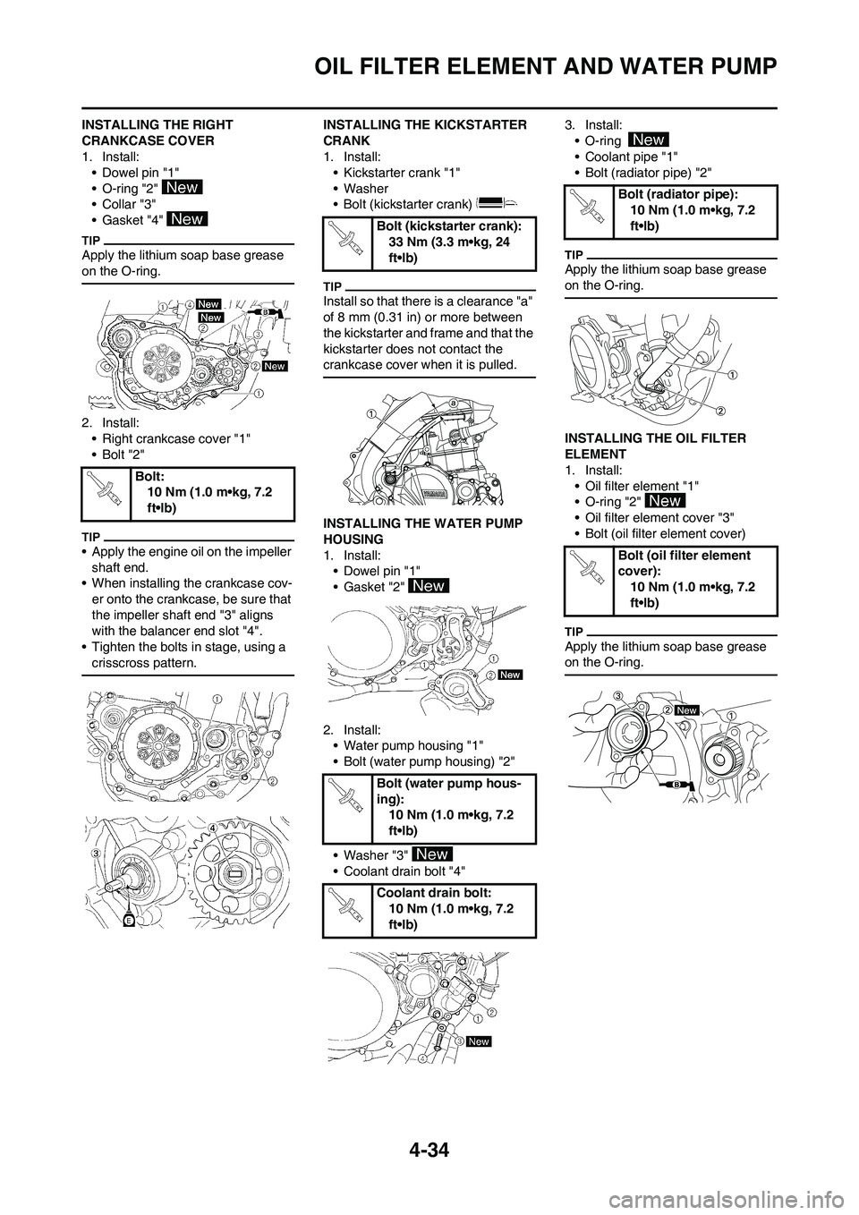
INSTALLING THE RIGHT
CRANKCASE COVER
1. Install:
• Dowel pin "1"
• O-ring "2"
•Collar "3"
• Gasket "4"
Apply the lithium soap base grease
on the O-ring.
2. Install:
• Right crankcase cover "1"
•Bolt "2"
• Apply the engine oil on the impeller
shaft end.
• When installing the crankcase cov-
er onto the crankcase, be sure that
the impeller shaft end "3" aligns
with the balancer end slot "4".
• Tighten the bolts in stage, using a
crisscross pattern.
INSTALLING THE KICKSTARTER
CRANK
1. Install:
• Kickstarter crank "1"
• Washer
• Bolt (kickstarter crank)
Install so that there is a clearance "a"
of 8 mm (0.31 in) or more between
the kickstarter and frame and that the
kickstarter does not contact the
crankcase cover when it is pulled.
INSTALLING THE WATER PUMP
HOUSING
1. Install:
• Dowel pin "1"
• Gasket "2"
2. Install:
• Water pump housing "1"
• Bolt (water pump housing) "2"
• Washer "3"
• Coolant drain bolt "4"3. Install:
• O-ring
• Coolant pipe "1"
• Bolt (radiator pipe) "2"
Apply the lithium soap base grease
on the O-ring.
INSTALLING THE OIL FILTER
ELEMENT
1. Install:
• Oil filter element "1"
• O-ring "2"
• Oil filter element cover "3"
• Bolt (oil filter element cover)
Apply the lithium soap base grease
on the O-ring.
Bolt:
10 Nm (1.0 m•kg, 7.2
ft•lb)
Bolt (kickstarter crank):
33 Nm (3.3 m•kg, 24
ft•lb)
Bolt (water pump hous-
ing):
10 Nm (1.0 m•kg, 7.2
ft•lb)
Coolant drain bolt:
10 Nm (1.0 m•kg, 7.2
ft•lb)
Bolt (radiator pipe):
10 Nm (1.0 m•kg, 7.2
ft•lb)
Bolt (oil filter element
cover):
10 Nm (1.0 m•kg, 7.2
ft•lb)
Page 116 of 230

4-35
BALANCER
BALANCER
REMOVING THE BALANCER
Order Part name Q'ty Remarks
Primary driven gear Refer to "CLUTCH" section.
Right crankcase cover Refer to "OIL FILTER ELEMENT AND WA-
TER PUMP" section.
Stator Refer to "AC MAGNETO" section.
1 Nut (balancer) 1 Refer to removal section.
2 Nut (primary drive gear) 1 Refer to removal section.
3 Nut (balancer shaft driven gear) 1 Refer to removal section.
4 Lock washer 1
5 Balancer 1
6 Straight key 1
7 Conical washer 1
8 Primary drive gear 1
9 Balancer shaft drive gear 1
10 Lock washer 1
11 Balancer shaft driven gear 1
Page 118 of 230

4-37
OIL PUMP
OIL PUMP
REMOVING THE OIL PUMP
Order Part name Q'ty Remarks
Primary driven gear Refer to "CLUTCH" section.
Right crankcase coverRefer to "OIL FILTER ELEMENT AND WA-
TER PUMP" section.
1 Circlip 1
2 Washer 1
3 Oil pump drive gear 1
4 Oil pump assembly 1
5 Dowel pin 2
6 Outer rotor 2 1
7 Circlip 1
8 Inner rotor 2 1
9 Dowel pin 1
10 Oil pump cover 1
11 Outer rotor 1 1
12 Inner rotor 1 1
13 Dowel pin 1
14 Washer 1
Page 128 of 230
4-47
ENGINE REMOVAL
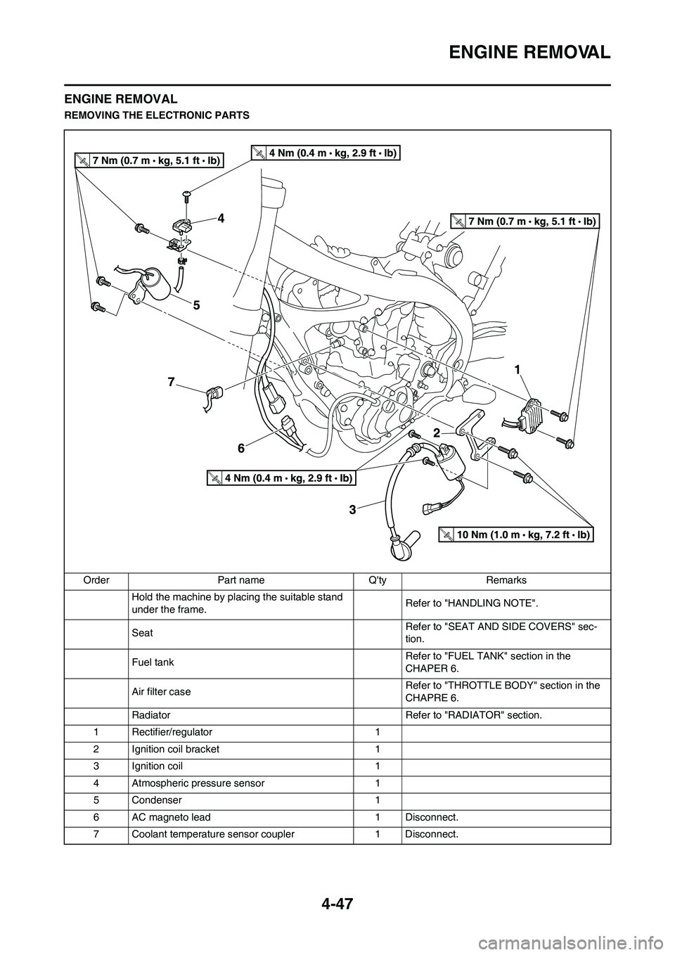
ENGINE REMOVAL
REMOVING THE ELECTRONIC PARTS
Order Part name Q'ty Remarks
Hold the machine by placing the suitable stand
under the frame.Refer to "HANDLING NOTE".
SeatRefer to "SEAT AND SIDE COVERS" sec-
tion.
Fuel tankRefer to "FUEL TANK" section in the
CHAPER 6.
Air filter caseRefer to "THROTTLE BODY" section in the
CHAPRE 6.
Radiator Refer to "RADIATOR" section.
1 Rectifier/regulator 1
2 Ignition coil bracket 1
3 Ignition coil 1
4 Atmospheric pressure sensor 1
5 Condenser 1
6 AC magneto lead 1 Disconnect.
7 Coolant temperature sensor coupler 1 Disconnect.