oil pressure YAMAHA YZ450F 2011 Owners Manual
[x] Cancel search | Manufacturer: YAMAHA, Model Year: 2011, Model line: YZ450F, Model: YAMAHA YZ450F 2011Pages: 230, PDF Size: 14.09 MB
Page 17 of 230
1-7
FEATURES
FEATURES
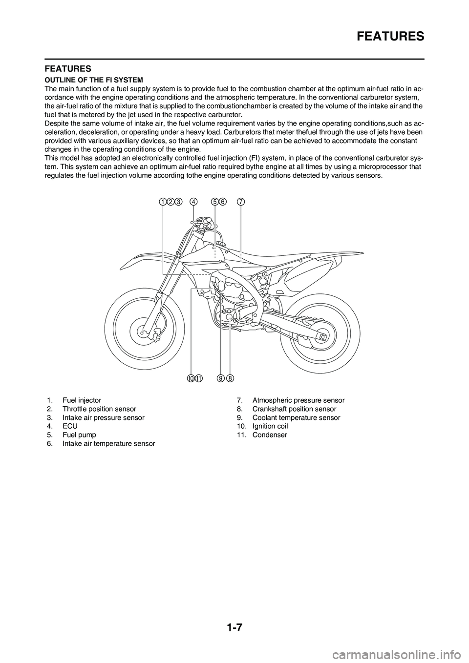
OUTLINE OF THE FI SYSTEM
The main function of a fuel supply system is to provide fuel to the combustion chamber at the optimum air-fuel ratio in ac-
cordance with the engine operating conditions and the atmospheric temperature. In the conventional carburetor system,
the air-fuel ratio of the mixture that is supplied to the combustionchamber is created by the volume of the intake air and the
fuel that is metered by the jet used in the respective carburetor.
Despite the same volume of intake air, the fuel volume requirement varies by the engine operating conditions,such as ac-
celeration, deceleration, or operating under a heavy load. Carburetors that meter thefuel through the use of jets have been
provided with various auxiliary devices, so that an optimum air-fuel ratio can be achieved to accommodate the constant
changes in the operating conditions of the engine.
This model has adopted an electronically controlled fuel injection (FI) system, in place of the conventional carburetor sys-
tem. This system can achieve an optimum air-fuel ratio required bythe engine at all times by using a microprocessor that
regulates the fuel injection volume according tothe engine operating conditions detected by various sensors.
1. Fuel injector
2. Throttle position sensor
3. Intake air pressure sensor
4. ECU
5. Fuel pump
6. Intake air temperature sensor7. Atmospheric pressure sensor
8. Crankshaft position sensor
9. Coolant temperature sensor
10. Ignition coil
11. Condenser
Page 23 of 230
1-13
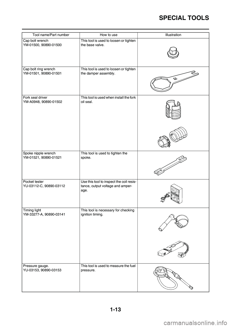
SPECIAL TOOLS
Cap bolt wrench
YM-01500, 90890-01500This tool is used to loosen or tighten
the base valve.
Cap bolt ring wrench
YM-01501, 90890-01501This tool is used to loosen or tighten
the damper assembly.
Fork seal driver
YM-A0948, 90890-01502 This tool is used when install the fork
oil seal.
Spoke nipple wrench
YM-01521, 90890-01521 This tool is used to tighten the
spoke.
Pocket tester
YU-03112-C, 90890-03112 Use this tool to inspect the coil resis-
tance, output voltage and amper-
age.
Timing light
YM-33277-A, 90890-03141 This tool is necessary for checking
ignition timing.
Pressure gauge.
YU-03153, 90890-03153 This tool is used to measure the fuel
pressure. Tool name/Part number How to use Illustration
Page 30 of 230
1-20
CLEANING AND STORAGE
CLEANING AND STORAGE
CLEANING
Frequent cleaning of your machine
will enhance its appearance, maintain
good overall performance, and ex-
tend the life of many components.
1. Before washing the machine,
block off the end of the exhaust
pipe to prevent water from enter-
ing. A plastic bag secured with a
rubber band may be used for this
purpose.
2. If the engine is excessively
greasy, apply some degreaser to
it with a paint brush. Do not apply
degreaser to the chain, sprockets,
or wheel axles.
3. Rinse the dirt and degreaser off
with a garden hose; use only
enough pressure to do the job.
Do not use high-pressure washers
or steam-jet cleaners since they
cause water seepage and deterio-
ration seals.
4. After the majority of the dirt has
been hosed off, wash all surfaces
with warm water and a mild deter-
gent. Use an old toothbrush to
clean hard-to-reach places.
5. Rinse the machine off immediate-
ly with clean water, and dry all
surfaces with a soft towel or cloth.
6. Immediately after washing, re-
move excess water from the
chain with a paper towel and lubri-
cate the chain to prevent rust.
7. Clean the seat with a vinyl uphol-
stery cleaner to keep the cover
pliable and glossy.
8. Automotive wax may be applied
to all painted or chromed surfac-
es. Avoid combination cleaner-
waxes, as they may contain abra-
sives.
9. After completing the above, start
the engine and allow it to idle for
several minutes.STORAGE
If your machine is to be stored for 60
days or more, some preventive mea-
sures must be taken to avoid deterio-
ration. After cleaning the machine
thoroughly, prepare it for storage as
follows:
1. Fill up the fuel tank and add fuel
stabilizer (if available) to prevent
the fuel tank from rusting and the
fuel from deteriorating.
2. Remove the spark plug, pour a ta-
blespoon of SAE 10W-40 motor
oil in the spark plug hole, and re-
install the plug. With the engine
stop switch pushed in, kick the en-
gine over several times to coat the
cylinder walls with oil.
3. Remove the drive chain, clean it
thoroughly with solvent, and lubri-
cate it. Reinstall the chain or store
it in a plastic bag tied to the frame.
4. Lubricate all control cables.
5. Block the frame up to raise the
wheels off the ground.
6. Tie a plastic bag over the exhaust
pipe outlet to prevent moisture
from entering.
7. If the machine is to be stored in a
humid or salt-air environment,
coat all exposed metal surfaces
with a film of light oil. Do not apply
oil to rubber parts or the seat cov-
er.
Make any necessary repairs before
the machine is stored.
Page 32 of 230
2-2
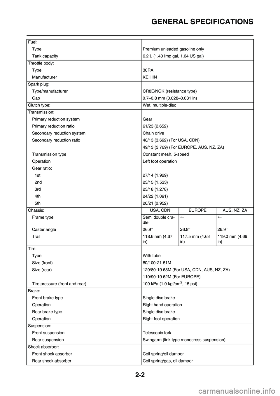
GENERAL SPECIFICATIONS
Fuel:Type Premium unleaded gasoline only
Tank capacity 6.2 L (1.40 Imp gal, 1.64 US gal)
Throttle body: Type 30RA
Manufacturer KEIHIN
Spark plug: Type/manufacturer CR8E/NGK (resistance type)
Gap 0.7–0.8 mm (0.028–0.031 in)
Clutch type: Wet, multiple-disc
Transmission: Primary reduction system Gear
Primary reduction ratio 61/23 (2.652)
Secondary reduction system Chain drive
Secondary reduction ratio 48/13 (3.692) (For USA, CDN)
49/13 (3.769) (For EUROPE, AUS, NZ, ZA)
Transmission type Constant mesh, 5-speed
Operation Left foot operation
Gear ratio: 1st 27/14 (1.929)
2nd 23/15 (1.533)
3rd 23/18 (1.278)
4th 24/22 (1.091)
5th 20/21 (0.952)
Chassis: USA, CDN EUROPE AUS, NZ, ZA Frame type Semi double cra- dle←←
Caster angle 26.9° 26.8° 26.9°
Trail 118.6 mm (4.67 in)117.5 mm (4.63
in)119.0 mm (4.69
in)
Tire: Type With tube
Size (front) 80/100-21 51M
Size (rear) 120/80-19 63M (F or USA, CDN, AUS, NZ, ZA)
110/90-19 62M (For EUROPE)
Tire pressure (front and rear) 100 kPa (1.0 kgf/cm
2, 15 psi)
Brake: Front brake type Single disc brake
Operation Right hand operation
Rear brake type Single disc brake
Operation Right foot operation
Suspension: Front suspension Telescopic fork
Rear suspension Swingarm (link type monocross suspension)
Shock absorber: Front shock absorber Coil spring/oil damper
Rear shock absorber Coil spring/gas, oil damper
Page 37 of 230

2-7
MAINTENANCE SPECIFICATIONS
Crankshaft:
Crank width "A" 61.95–62.00 mm (2.439–2.441 in) ----
Runout limit "C" 0.03 mm (0.0012 in) 0.05 mm (0.002
in)
Big end side clearance "D" 0.15–0.45 mm (0.0059–0.0177 in) 0.50 mm (0.02
in)
Small end free play "F" 0.4–1.0 mm (0.02–0.04 in) 2.0 mm (0.08
in)
Balancer:
Balancer drive method Gear ----
Air filter oil grade: Foam-air-filter oil or equivalent oil ----
Clutch:
Friction plate thickness 2.92–3.08 mm (0.115–0.121 in) 2.8 mm (0.110
in)
Quantity 8 ----
Clutch plate thickness 1.5–1.7 mm (0.059–0.067 in) ----
Quantity 7 ----
Warp limit ---- 0.1 mm (0.004
in)
Clutch spring free length 50.0 mm (1.97 in) 49.0 mm (1.93
in)
Quantity 6 ----
Clutch housing thrust clearance 0.10–0.35 mm (0.0039–0.0138 in) ----
Clutch housing radial clearance 0.010–0.044 mm (0.0004–0.0017 in) ----
Clutch release method Inner push, cam push ----
Shifter:
Shifter type Cam drum and guide bar ----
Guide bar bending limit ---- 0.05 mm (0.002
in)
Kickstarter:
Type Kick and ratchet type ----
Fuel pump:
Fuel pressure 324 kPa (3.24 kg/cm
2, 46.1 psi) ----
Fuel injector:----
Model/manufacturer 1010/DENSO ----
Throttle body:----
I. D. mark 33D1 00 ----
Manufacturer KEIHIN ----Item Standard Limit
Page 38 of 230
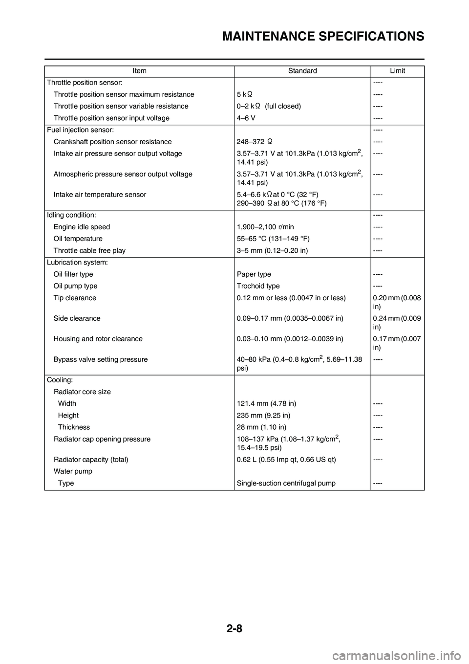
2-8
MAINTENANCE SPECIFICATIONS
Throttle position sensor:----
Throttle position sensor maximum resistance 5 kΩ----
Throttle position sensor variable resistance 0–2 kΩ (full closed) ----
Throttle position sensor input voltage 4–6 V ----
Fuel injection sensor:----
Crankshaft position sensor resistance 248–372 Ω----
Intake air pressure sensor output voltage 3.57–3.71 V at 101.3kPa (1.013 kg/cm
2,
14.41 psi)----
Atmospheric pressure sensor output voltage 3.57–3.71 V at 101.3kPa (1.013 kg/cm
2,
14.41 psi)----
Intake air temperature sensor 5.4–6.6 kΩat 0 °C (32 °F)
290–390 Ωat 80 °C (176 °F)----
Idling condition:----
Engine idle speed 1,900–2,100 r/min ----
Oil temperature 55–65 °C (131–149 °F) ----
Throttle cable free play 3–5 mm (0.12–0.20 in) ----
Lubrication system:
Oil filter type Paper type ----
Oil pump type Trochoid type ----
Tip clearance 0.12 mm or less (0.0047 in or less) 0.20 mm (0.008
in)
Side clearance 0.09–0.17 mm (0.0035–0.0067 in) 0.24 mm (0.009
in)
Housing and rotor clearance 0.03–0.10 mm (0.0012–0.0039 in) 0.17 mm (0.007
in)
Bypass valve setting pressure 40–80 kPa (0.4–0.8 kg/cm
2, 5.69–11.38
psi)----
Cooling:
Radiator core size
Width 121.4 mm (4.78 in) ----
Height 235 mm (9.25 in) ----
Thickness 28 mm (1.10 in) ----
Radiator cap opening pressure 108–137 kPa (1.08–1.37 kg/cm
2,
15.4–19.5 psi)----
Radiator capacity (total) 0.62 L (0.55 Imp qt, 0.66 US qt) ----
Water pump
Type Single-suction centrifugal pump ----Item Standard Limit
Page 39 of 230
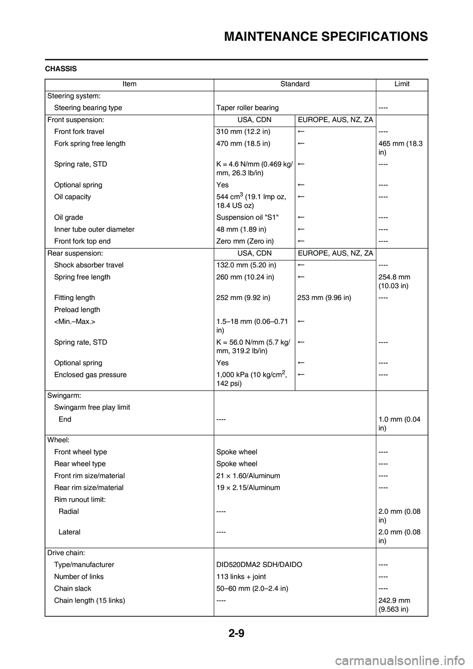
2-9
MAINTENANCE SPECIFICATIONS
CHASSIS
Item Standard Limit
Steering system:
Steering bearing typeTaper roller bearing ----
Front suspension: USA, CDN EUROPE, AUS, NZ, ZA
Front fork travel 310 mm (12.2 in)←----
Fork spring free length 470 mm (18.5 in)←465 mm (18.3
in)
Spring rate, STD K = 4.6 N/mm (0.469 kg/
mm, 26.3 lb/in)←----
Optional spring Yes←----
Oil capacity 544 cm
3 (19.1 lmp oz,
18.4 US oz)←----
Oil grade Suspension oil "S1"←----
Inner tube outer diameter 48 mm (1.89 in)←----
Front fork top end Zero mm (Zero in)←----
Rear suspension: USA, CDN EUROPE, AUS, NZ, ZA
Shock absorber travel 132.0 mm (5.20 in)←----
Spring free length 260 mm (10.24 in)←254.8 mm
(10.03 in)
Fitting length 252 mm (9.92 in) 253 mm (9.96 in) ----
Preload length
in)←
Spring rate, STD K = 56.0 N/mm (5.7 kg/
mm, 319.2 lb/in)←----
Optional spring Yes←----
Enclosed gas pressure 1,000 kPa (10 kg/cm
2,
142 psi)←----
Swingarm:
Swingarm free play limit
End ---- 1.0 mm (0.04
in)
Wheel:
Front wheel type Spoke wheel ----
Rear wheel typeSpoke wheel ----
Front rim size/material 21 × 1.60/Aluminum ----
Rear rim size/material 19 × 2.15/Aluminum ----
Rim runout limit:
Radial ---- 2.0 mm (0.08
in)
Lateral ---- 2.0 mm (0.08
in)
Drive chain:
Type/manufacturer DID520DMA2 SDH/DAIDO ----
Number of links 113 links + joint ----
Chain slack 50–60 mm (2.0–2.4 in) ----
Chain length (15 links) ---- 242.9 mm
(9.563 in)
Page 41 of 230
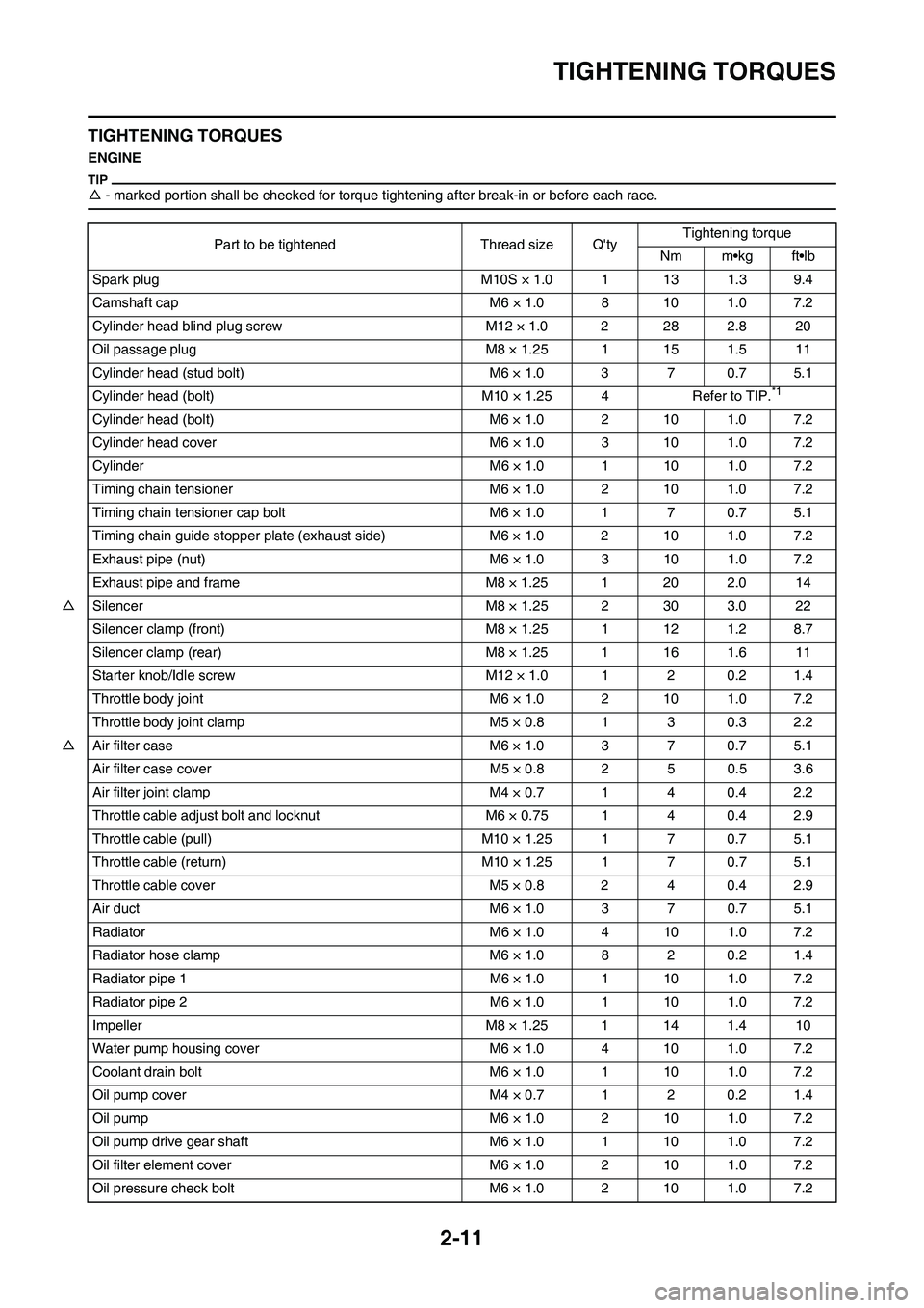
2-11
TIGHTENING TORQUES
TIGHTENING TORQUES
ENGINE
△- marked portion shall be checked for torque tightening after break-in or before each race.
Part to be tightened Thread size Q'tyTightening torque
Nm m•kg ft•lb
Spark plug M10S × 1.0 1 13 1.3 9.4
Camshaft cap M6 × 1.0 8 10 1.0 7.2
Cylinder head blind plug screw M12 × 1.0 2 28 2.8 20
Oil passage plug M8 × 1.25 1 15 1.5 11
Cylinder head (stud bolt) M6 × 1.0 3 7 0.7 5.1
Cylinder head (bolt) M10 × 1.25 4 Refer to TIP.
*1
Cylinder head (bolt) M6 × 1.0 2 10 1.0 7.2
Cylinder head cover M6 × 1.0 3 10 1.0 7.2
Cylinder M6 × 1.0 1 10 1.0 7.2
Timing chain tensioner M6 × 1.0 2 10 1.0 7.2
Timing chain tensioner cap bolt M6 × 1.0 1 7 0.7 5.1
Timing chain guide stopper plate (exhaust side) M6 × 1.0 2 10 1.0 7.2
Exhaust pipe (nut) M6 × 1.0 3 10 1.0 7.2
Exhaust pipe and frame M8 × 1.25 1 20 2.0 14
△Silencer M8 × 1.25 2 30 3.0 22
Silencer clamp (front) M8 × 1.25 1 12 1.2 8.7
Silencer clamp (rear) M8 × 1.25 1 16 1.6 11
Starter knob/Idle screw M12 × 1.0 1 2 0.2 1.4
Throttle body joint M6 × 1.0 2 10 1.0 7.2
Throttle body joint clamp M5 × 0.8 1 3 0.3 2.2
△Air filter case M6 × 1.0 3 7 0.7 5.1
Air filter case cover M5 × 0.8 2 5 0.5 3.6
Air filter joint clamp M4 × 0.7 1 4 0.4 2.2
Throttle cable adjust bolt and locknut M6 × 0.75 1 4 0.4 2.9
Throttle cable (pull) M10 × 1.25 1 7 0.7 5.1
Throttle cable (return) M10 × 1.25 1 7 0.7 5.1
Throttle cable cover M5 × 0.8 2 4 0.4 2.9
Air duct M6 × 1.0 3 7 0.7 5.1
Radiator M6 × 1.0 4 10 1.0 7.2
Radiator hose clamp M6 × 1.0 8 2 0.2 1.4
Radiator pipe 1 M6 × 1.0 1 10 1.0 7.2
Radiator pipe 2 M6 × 1.0 1 10 1.0 7.2
Impeller M8 × 1.25 1 14 1.4 10
Water pump housing cover M6 × 1.0 4 10 1.0 7.2
Coolant drain bolt M6 × 1.0 1 10 1.0 7.2
Oil pump cover M4 × 0.7 1 2 0.2 1.4
Oil pump M6 × 1.0 2 10 1.0 7.2
Oil pump drive gear shaft M6 × 1.0 1 10 1.0 7.2
Oil filter element cover M6 × 1.0 2 10 1.0 7.2
Oil pressure check bolt M6 × 1.0 2 10 1.0 7.2
Page 45 of 230
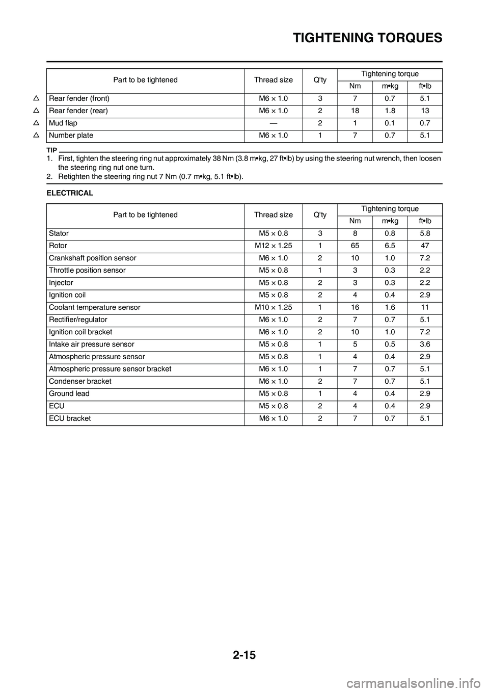
2-15
TIGHTENING TORQUES
1. First, tighten the steering ring nut approximately 38 Nm (3.8 m•kg, 27 ft•lb) by using the steering nut wrench, then loosen
the steering ring nut one turn.
2. Retighten the steering ring nut 7 Nm (0.7 m•kg, 5.1 ft•lb).
ELECTRICAL △Rear fender (front) M6 × 1.0 3 7 0.7 5.1
△Rear fender (rear) M6 × 1.0 2 18 1.8 13
△Mud flap — 2 1 0.1 0.7
△Number plate M6 × 1.0 1 7 0.7 5.1Part to be tightened Thread size Q'tyTightening torque
Nm m•kg ft•lb
Part to be tightened Thread size Q'tyTightening torque
Nm m•kg ft•lb
Stator M5 × 0.8 3 8 0.8 5.8
Rotor M12 × 1.25 1 65 6.5 47
Crankshaft position sensor M6 × 1.0 2 10 1.0 7.2
Throttle position sensor M5 × 0.8 1 3 0.3 2.2
Injector M5 × 0.8 2 3 0.3 2.2
Ignition coil M5 × 0.8 2 4 0.4 2.9
Coolant temperature sensor M10 × 1.25 1 16 1.6 11
Rectifier/regulator M6 × 1.0 2 7 0.7 5.1
Ignition coil bracket M6 × 1.0 2 10 1.0 7.2
Intake air pressure sensor M5 × 0.8 1 5 0.5 3.6
Atmospheric pressure sensor M5 × 0.8 1 4 0.4 2.9
Atmospheric pressure sensor bracket M6 × 1.0 1 7 0.7 5.1
Condenser bracket M6 × 1.0 2 7 0.7 5.1
Ground lead M5 × 0.8 1 4 0.4 2.9
ECU M5 × 0.8 2 4 0.4 2.9
ECU bracket M6 × 1.0 2 7 0.7 5.1
Page 53 of 230
2-23
CABLE ROUTING DIAGRAM
1. Tension pipe
2. Coolant temperature sensor
coupler
3. Front engine bracket
4. Fuel pump coupler
5. Fuel pump
6. Intake air temperature sensor
coupler
7. Radiator hose 2
8. Radiator breather hose
9. Radiator hose 1
10. Radiator hose 4
11. Radiator pipe 2
12. Radiator hose 3
13. Cylinder head breather hose
14. Frame
15. ECU (electronic control unit)
16. ECU bracket
17. Main harness
18. AC magneto lead
19. Throttle position sensor lead
20. Condenser lead
21. Coolant temperature sensor
lead
22. Ignition coil lead
23. CondenserA. Fasten the wire harness at the
positioning tape to the ECU
bracket with a plastic locking tie.
Face the buckle of the plastic
locking tie downward, and then
cut off the excess end of the tie.
B. Install the cover onto the wire
harness coupler.
C. Route the condenser lead, throt-
tle position sensor lead, coolant
temperature sensor lead, igni-
tion coil lead, and AC magneto
lead under radiator hose 2.
D. Connect the vacuum hose to the
atmospheric pressure sensor,
and then fasten the hose with
the clamp. Make sure to face the
moving part of the sensor rear-
ward.
E. After connecting the condenser
coupler, install the coupler cover
onto the coupler.
F. After connecting the throttle po-
sition sensor coupler, install the
coupler cover onto the coupler.
G. Fasten the AC magneto lead,
condenser lead, throttle position
sensor lead, coolant tempera-
ture sensor lead, and ignition
coil lead to the frame with the
plastic band, making sure to po-
sition the band between the igni-
tion coil bracket and the tension
pipe. Face the buckle of the
plastic band to the right with the
end pointing rearward.
H. Point the end of the vacuum
hose rearward.
I. Fit the bracket into the hole in
the rubber portion of the con-
denser.
J. Fasten the radiator breather
hose to the frame with the plas-
tic band, making sure to position
the band above the front engine
bracket. Face the buckle of the
plastic band outward with the
end pointing rearward.
K. After connecting the coolant
temperature sensor coupler, in-
stall the coupler cover onto the
coupler.L. Route the radiator breather hose
between the down tubes.
M. Fasten the fuel hose and fuel
pump lead with the plastic band,
making sure to position the band
between the bend in the fuel
hose protector and the end of
the protector. Point the end of
the plastic band upward.
N. Insert the projection on the joint
coupler into the hole in the
bracket, and then install the cou-
pler cover onto the coupler.
O. Route the atmospheric pressure
sensor lead, intake air pressure
sensor lead, intake air tempera-
ture sensor lead, fuel injector
lead, and fuel pump lead above
radiator hose 2. Position the
joint coupler above radiator
hose 2.
P. Route the radiator breather hose
to the inside of radiator hose 1
and the front engine bracket.
Q. Hose installation position
(1.3–3.3 mm, 0.05–0.13 in)
R. Clip installation position (0–2.0
mm, 0–0.08 in)
S. Install the washer so that it con-
tacts the bolt head.
T. Install the collar so that the
flange on the collar contacts the
ECU bracket.