ad blue YAMAHA YZ450F 2012 Owners Manual
[x] Cancel search | Manufacturer: YAMAHA, Model Year: 2012, Model line: YZ450F, Model: YAMAHA YZ450F 2012Pages: 228, PDF Size: 11.42 MB
Page 91 of 228
4-10
CAMSHAFTS
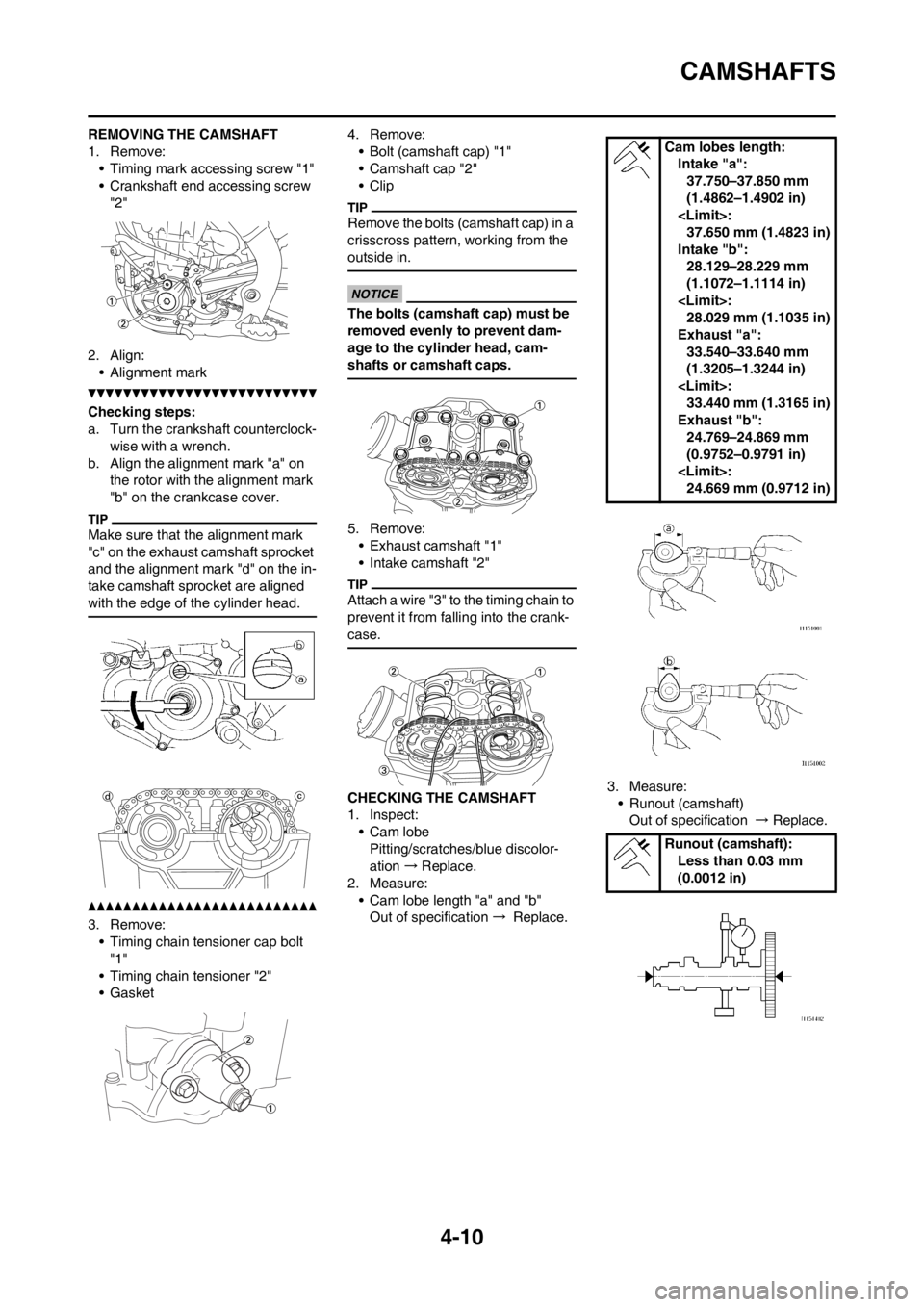
REMOVING THE CAMSHAFT
1. Remove:
• Timing mark accessing screw "1"
• Crankshaft end accessing screw
"2"
2. Align:
• Alignment mark
Checking steps:
a. Turn the crankshaft counterclock-
wise with a wrench.
b. Align the alignment mark "a" on
the rotor with the alignment mark
"b" on the crankcase cover.
Make sure that the alignment mark
"c" on the exhaust camshaft sprocket
and the alignment mark "d" on the in-
take camshaft sprocket are aligned
with the edge of the cylinder head.
3. Remove:
• Timing chain tensioner cap bolt
"1"
• Timing chain tensioner "2"
• Gasket4. Remove:
• Bolt (camshaft cap) "1"
• Camshaft cap "2"
• Clip
Remove the bolts (camshaft cap) in a
crisscross pattern, working from the
outside in.
The bolts (camshaft cap) must be
removed evenly to prevent dam-
age to the cylinder head, cam-
shafts or camshaft caps.
5. Remove:
• Exhaust camshaft "1"
• Intake camshaft "2"
Attach a wire "3" to the timing chain to
prevent it from falling into the crank-
case.
CHECKING THE CAMSHAFT
1. Inspect:
• Cam lobe
Pitting/scratches/blue discolor-
ation → Replace.
2. Measure:
• Cam lobe length "a" and "b"
Out of specification → Replace.3. Measure:
• Runout (camshaft)
Out of specification → Replace.
Cam lobes length:
Intake "a":
37.750–37.850 mm
(1.4862–1.4902 in)
37.650 mm (1.4823 in)
Intake "b":
28.129–28.229 mm
(1.1072–1.1114 in)
28.029 mm (1.1035 in)
Exhaust "a":
33.540–33.640 mm
(1.3205–1.3244 in)
33.440 mm (1.3165 in)
Exhaust "b":
24.769–24.869 mm
(0.9752–0.9791 in)
24.669 mm (0.9712 in)
Runout (camshaft):
Less than 0.03 mm
(0.0012 in)
Page 100 of 228
4-19
VALVES AND VALVE SPRINGS
3. Inspect:
• Valve face
Pitting/wear → Grind the face.
• Valve stem end
Mushroom shape or diameter
larger than the body of the stem
→ Replace.
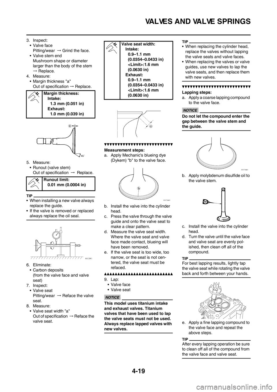
4. Measure:
• Margin thickness "a"
Out of specification → Replace.
5. Measure:
• Runout (valve stem)
Out of specification → Replace.
• When installing a new valve always
replace the guide.
• If the valve is removed or replaced
always replace the oil seal.
6. Eliminate:
• Carbon deposits
(from the valve face and valve
seat)
7. Inspect:
• Valve seat
Pitting/wear → Reface the valve
seat.
8. Measure:
• Valve seat width "a"
Out of specification → Reface the
valve seat.
Measurement steps:
a. Apply Mechanic's blueing dye
(Dykem) "b" to the valve face.
b. Install the valve into the cylinder
head.
c. Press the valve through the valve
guide and onto the valve seat to
make a clear pattern.
d. Measure the valve seat width.
Where the valve seat and valve
face made contact, blueing will
have been removed.
e. If the valve seat is too wide, too
narrow, or the seat is not cen-
tered, the valve seat must be
refaced.
9. Lap:
• Valve face
• Valve seat
This model uses titanium intake
and exhaust valves. Titanium
valves that have been used to lap
the valve seats must not be used.
Always replace lapped valves with
new valves.
• When replacing the cylinder head,
replace the valves without lapping
the valve seats and valve faces.
• When replacing the valves or valve
guides, use new valves to lap the
valve seats, and then replace them
with new valves.
Lapping steps:
a. Apply a coarse lapping compound
to the valve face.
Do not let the compound enter the
gap between the valve stem and
the guide.
b. Apply molybdenum disulfide oil to
the valve stem.
c. Install the valve into the cylinder
head.
d. Turn the valve until the valve face
and valve seat are evenly pol-
ished, then clean off all of the
compound.
For best lapping results, lightly tap
the valve seat while rotating the valve
back and forth between your hands.
e. Apply a fine lapping compound to
the valve face and repeat the
above steps.
After every lapping operation be sure
to clean off all of the compound from
the valve face and valve seat.
Margin thickness:
Intake:
1.3 mm (0.051 in)
Exhaust:
1.0 mm (0.039 in)
Runout limit:
0.01 mm (0.0004 in)
Valve seat width:
Intake:
0.9–1.1 mm
(0.0354–0.0433 in)
(0.0630 in)
Exhaust:
0.9–1.1 mm
(0.0354–0.0433 in)
(0.0630 in)
Page 101 of 228
4-20
VALVES AND VALVE SPRINGS
f. Apply Mechanic's blueing dye
(Dykem) to the valve face.
g. Install the valve into the cylinder
head.
h. Press the valve through the valve
guide and onto the valve seat to
make a clear pattern.
i. Measure the valve seat width
again. If the valve seat width is out
of specification, reface and relap
the valve seat.
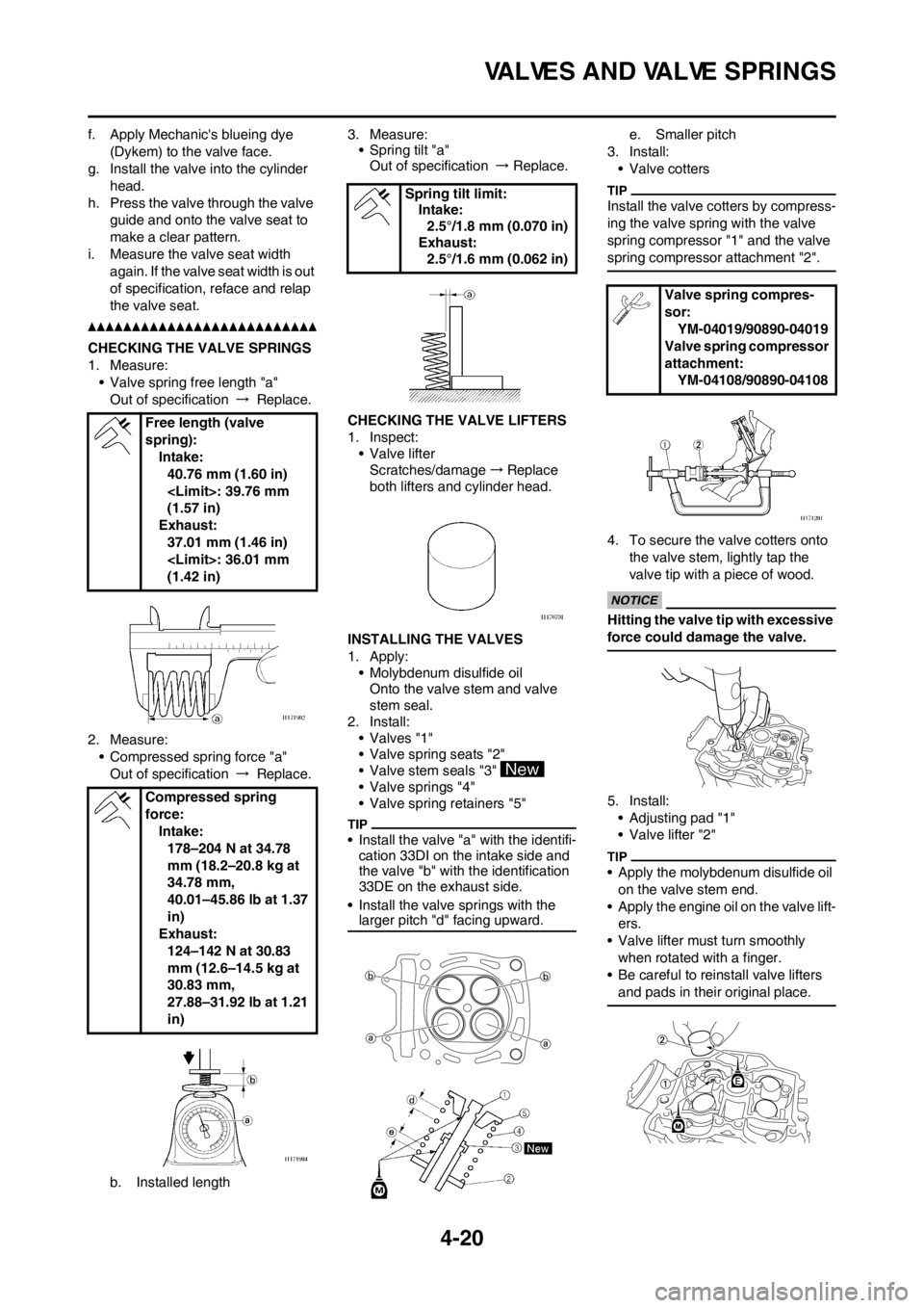
CHECKING THE VALVE SPRINGS
1. Measure:
• Valve spring free length "a"
Out of specification → Replace.
2. Measure:
• Compressed spring force "a"
Out of specification → Replace.
b. Installed length3. Measure:
• Spring tilt "a"
Out of specification → Replace.
CHECKING THE VALVE LIFTERS
1. Inspect:
• Valve lifter
Scratches/damage→Replace
both lifters and cylinder head.
INSTALLING THE VALVES
1. Apply:
• Molybdenum disulfide oil
Onto the valve stem and valve
stem seal.
2. Install:
• Valves "1"
• Valve spring seats "2"
• Valve stem seals "3"
• Valve springs "4"
• Valve spring retainers "5"
• Install the valve "a" with the identifi-
cation 33DI on the intake side and
the valve "b" with the identification
33DE on the exhaust side.
• Install the valve springs with the
larger pitch "d" facing upward.
e. Smaller pitch
3. Install:
• Valve cotters
Install the valve cotters by compress-
ing the valve spring with the valve
spring compressor "1" and the valve
spring compressor attachment "2".
4. To secure the valve cotters onto
the valve stem, lightly tap the
valve tip with a piece of wood.
Hitting the valve tip with excessive
force could damage the valve.
5. Install:
• Adjusting pad "1"
• Valve lifter "2"
• Apply the molybdenum disulfide oil
on the valve stem end.
• Apply the engine oil on the valve lift-
ers.
• Valve lifter must turn smoothly
when rotated with a finger.
• Be careful to reinstall valve lifters
and pads in their original place.
Free length (valve
spring):
Intake:
40.76 mm (1.60 in)
(1.57 in)
Exhaust:
37.01 mm (1.46 in)
(1.42 in)
Compressed spring
force:
Intake:
178–204 N at 34.78
mm (18.2–20.8 kg at
34.78 mm,
40.01–45.86 lb at 1.37
in)
Exhaust:
124–142 N at 30.83
mm (12.6–14.5 kg at
30.83 mm,
27.88–31.92 lb at 1.21
in)
Spring tilt limit:
Intake:
2.5°/1.8 mm (0.070 in)
Exhaust:
2.5°/1.6 mm (0.062 in)
Valve spring compres-
sor:
YM-04019/90890-04019
Valve spring compressor
attachment:
YM-04108/90890-04108
Page 104 of 228
4-23
CYLINDER AND PISTON
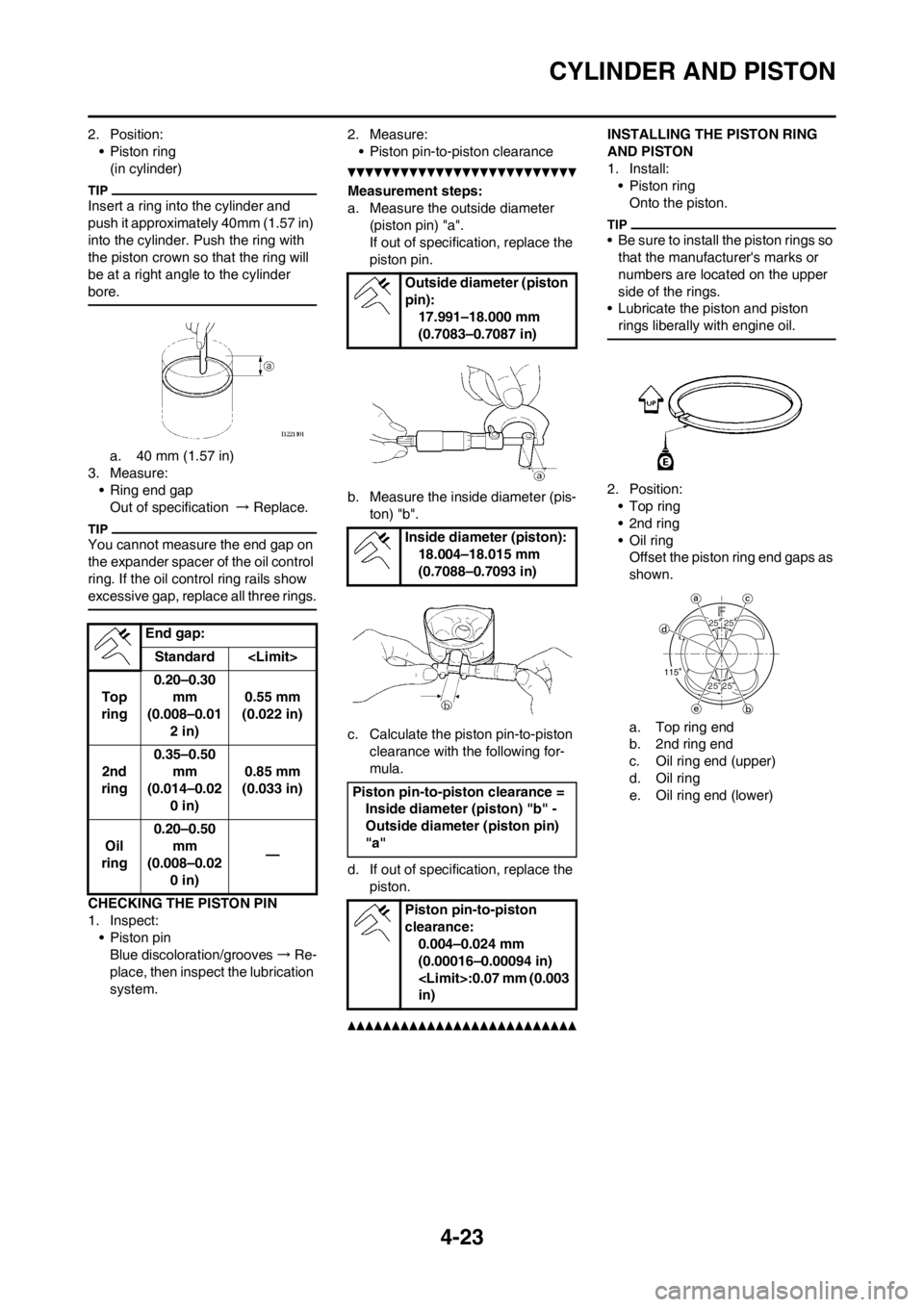
2. Position:
• Piston ring
(in cylinder)
Insert a ring into the cylinder and
push it approximately 40mm (1.57 in)
into the cylinder. Push the ring with
the piston crown so that the ring will
be at a right angle to the cylinder
bore.
a. 40 mm (1.57 in)
3. Measure:
• Ring end gap
Out of specification → Replace.
You cannot measure the end gap on
the expander spacer of the oil control
ring. If the oil control ring rails show
excessive gap, replace all three rings.
CHECKING THE PISTON PIN
1. Inspect:
• Piston pin
Blue discoloration/grooves→Re-
place, then inspect the lubrication
system.2. Measure:
• Piston pin-to-piston clearance
Measurement steps:
a. Measure the outside diameter
(piston pin) "a".
If out of specification, replace the
piston pin.
b. Measure the inside diameter (pis-
ton) "b".
c. Calculate the piston pin-to-piston
clearance with the following for-
mula.
d. If out of specification, replace the
piston.
INSTALLING THE PISTON RING
AND PISTON
1. Install:
• Piston ring
Onto the piston.
• Be sure to install the piston rings so
that the manufacturer's marks or
numbers are located on the upper
side of the rings.
• Lubricate the piston and piston
rings liberally with engine oil.
2. Position:
•Top ring
•2nd ring
•Oil ring
Offset the piston ring end gaps as
shown.
a. Top ring end
b. 2nd ring end
c. Oil ring end (upper)
d. Oil ring
e. Oil ring end (lower) End gap:
Standard
Top
ring0.20–0.30
mm
(0.008–0.01
2 in)0.55 mm
(0.022 in)
2nd
ring0.35–0.50
mm
(0.014–0.02
0 in)0.85 mm
(0.033 in)
Oil
ring0.20–0.50
mm
(0.008–0.02
0 in)—
Outside diameter (piston
pin):
17.991–18.000 mm
(0.7083–0.7087 in)
Inside diameter (piston):
18.004–18.015 mm
(0.7088–0.7093 in)
Piston pin-to-piston clearance =
Inside diameter (piston) "b" -
Outside diameter (piston pin)
"a"
Piston pin-to-piston
clearance:
0.004–0.024 mm
(0.00016–0.00094 in)
in)
2525
2525115
Page 186 of 228
7-2
ELECTRICAL COMPONENTS AND WIRING DIAGRAM
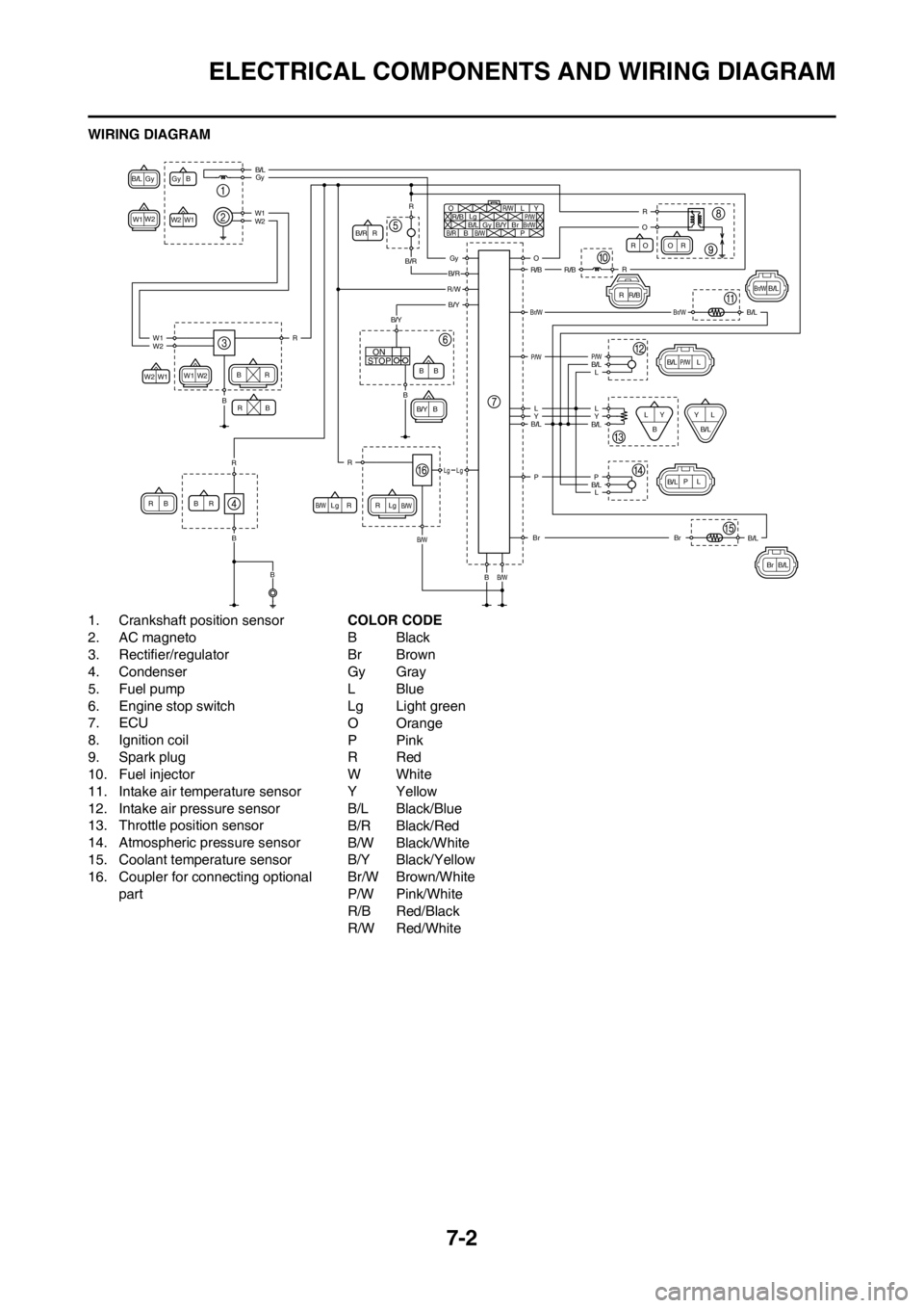
WIRING DIAGRAM
1. Crankshaft position sensor
2. AC magneto
3. Rectifier/regulator
4. Condenser
5. Fuel pump
6. Engine stop switch
7. ECU
8. Ignition coil
9. Spark plug
10. Fuel injector
11. Intake air temperature sensor
12. Intake air pressure sensor
13. Throttle position sensor
14. Atmospheric pressure sensor
15. Coolant temperature sensor
16. Coupler for connecting optional part COLOR CODE
BBlack
Br Brown
Gy Gray
LBlue
Lg Light green
O Orange
PPink
RRed
WWhite
YYellow
B/L Black/Blue
B/R Black/Red
B/W Black/White
B/Y Black/Yellow
Br/W Brown/White
P/W Pink/White
R/B Red/Black
R/W Red/White
STOPON
Gy
Gy
B
B/L
W1
W2
W2 O
R/B
R RR
R
R
R R
Lg
Lg Lg L
P/W
P
YB/RB
B B
BB BB
BB/W
B/W B/W Br/WGyB/L
W1 W1
W2 W2 B/Y
B/Y Br
B/R
R/W
OO
R/B RR
R
L
P/W
PYL
L
LY
Br/WB/L
B/L B/L
B
B/L
B/L
Br
W1
Br/W
W2
R
R O
B/L
L
Y
B/L
Br
R
P
Gy
Gy
B/R
B/R
R/WB/Y
B/L
W1
W2
W1 R
R R
B
B/Y
Lg Lg
O
R/B R/B
Br/W
P/W P/W
LL
Y
B/L B/L
B/L
Br
B
B/W
B/W
B
B
B L
B/L P
Page 191 of 228
7-7
THROTTLE POSITION SENSOR SYSTEM
HANDLING NOTE
Do not loosen the screw (throttle
position sensor) "1" except when
changing the throttle position sen-
sor due to failure because it will
cause a drop in engine perfor-
mance.
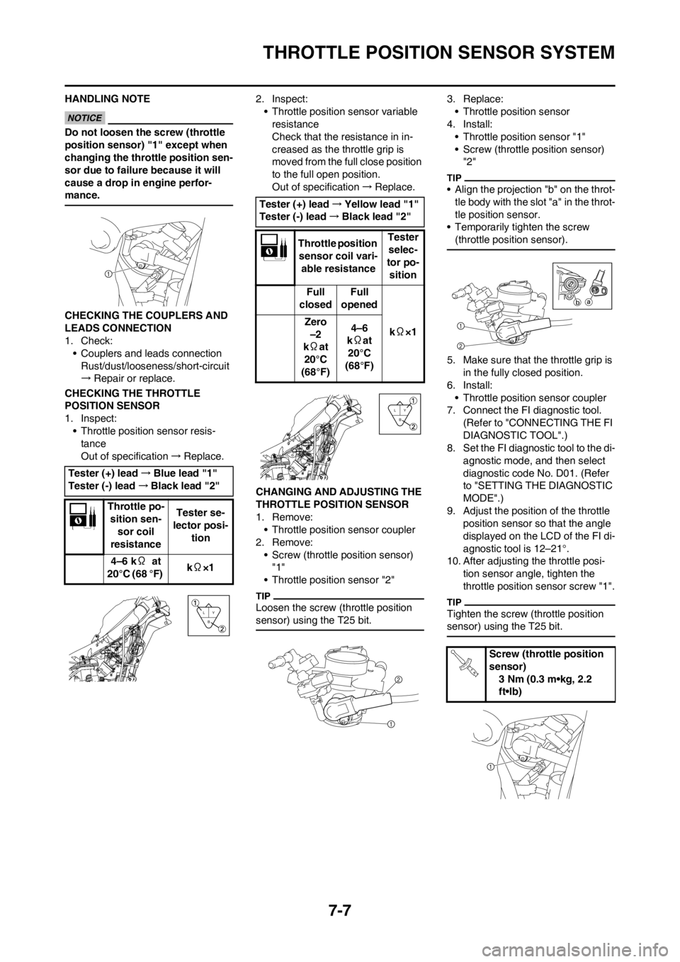
CHECKING THE COUPLERS AND
LEADS CONNECTION
1. Check:
• Couplers and leads connection
Rust/dust/looseness/short-circuit
→Repair or replace.
CHECKING THE THROTTLE
POSITION SENSOR
1. Inspect:
• Throttle position sensor resis-
tance
Out of specification→Replace.2. Inspect:
• Throttle position sensor variable
resistance
Check that the resistance in in-
creased as the throttle grip is
moved from the full close position
to the full open position.
Out of specification→Replace.
CHANGING AND ADJUSTING THE
THROTTLE POSITION SENSOR
1. Remove:
• Throttle position sensor coupler
2. Remove:
• Screw (throttle position sensor)
"1"
• Throttle position sensor "2"
Loosen the screw (throttle position
sensor) using the T25 bit.
3. Replace:
• Throttle position sensor
4. Install:
• Throttle position sensor "1"
• Screw (throttle position sensor)
"2"
• Align the projection "b" on the throt-
tle body with the slot "a" in the throt-
tle position sensor.
• Temporarily tighten the screw
(throttle position sensor).
5. Make sure that the throttle grip is
in the fully closed position.
6. Install:
• Throttle position sensor coupler
7. Connect the FI diagnostic tool.
(Refer to "CONNECTING THE FI
DIAGNOSTIC TOOL".)
8. Set the FI diagnostic tool to the di-
agnostic mode, and then select
diagnostic code No. D01. (Refer
to "SETTING THE DIAGNOSTIC
MODE".)
9. Adjust the position of the throttle
position sensor so that the angle
displayed on the LCD of the FI di-
agnostic tool is 12–21°.
10. After adjusting the throttle posi-
tion sensor angle, tighten the
throttle position sensor screw "1".
Tighten the screw (throttle position
sensor) using the T25 bit.
Tester (+) lead→Blue lead "1"
Tester (-) lead→Black lead "2"
Throttle po-
sition sen-
sor coil
resistanceTester se-
lector posi-
tion
4–6 kΩ at
20°C (68 °F) kΩ×1
Y
B L
Tester (+) lead→Yellow lead "1"
Tester (-) lead→Black lead "2"
Throttle position
sensor coil vari-
able resistanceTester
selec-
tor po-
sition
Full
closedFull
opened
kΩ×1 Zero
–2
kΩat
20°C
(68°F)4–6
kΩat
20°C
(68°F)
Y
B L
Screw (throttle position
sensor)
3 Nm (0.3 m•kg, 2.2
ft•lb)
Page 192 of 228
7-8
THROTTLE POSITION SENSOR SYSTEM
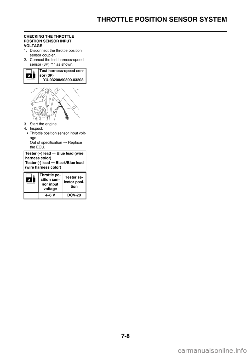
CHECKING THE THROTTLE
POSITION SENSOR INPUT
VOLTAGE
1. Disconnect the throttle position
sensor coupler.
2. Connect the test harness-speed
sensor (3P) "1" as shown.
3. Start the engine.
4. Inspect:
• Throttle position sensor input volt-
age
Out of specification → Replace
the ECU.Test harness-speed sen-
sor (3P)
YU-03208/90890-03208
Tester (+) lead→Blue lead (wire
harness color)
Tester (-) lead→Black/Blue lead
(wire harness color)
Throttle po-
sition sen-
sor input
voltage Tester se-
lector posi-
tion
4–6 V DCV-20
Page 197 of 228

7-13
FUEL INJECTION SYSTEM
TROUBLESHOOTING DETAILS
This section describes the countermeasures per fault code number displayed on the FI diagnostic tool. Check and service
the items or components that are the probable cause of the malfunction following the order given. After the check and ser-
vice of the malfunctioning part have been completed, reset the FI diagnostic tool display according to the "Reinstatement
method".
Fault code No.
Fault code number displayed on the FI diagnostic tool when the engine failed to work normally. Refer to "FAULT CODE
TABLE".
Diagnostic code No.
Diagnostic code number to be used when the diagnostic mode is operated. Refer to "DIAGNOSTIC CODE TABLE".
Fault code No. 12
Symptom No normal signals are received from the crankshaft position sensor.
Fail-safe system Able to start
Able to drive
Diagnostic code No. —
FI diagnostic tool display —
Checking method —
Item Item/components and probable cause Check or maintenance job Checking method
1 Check the connection and locking condition of
the crankshaft position sensor coupler.
Disconnect the coupler and check the pins.
(bent or broken terminals and locking condition
of the pins)Poor connection → Properly con-
nect, repair, or replace.Crank the engine and
check the fault code dis-
play.
Fault code number is not
displayed → Service is
finished.
Fault code number is dis-
played → Refer to item
2.
2 Check the connection and locking condition of
the wire harness ECU coupler.
Disconnect the coupler and check the pins.
(bent or broken terminals and locking condition
of the pins)Poor connection → Properly con-
nect, repair, or replace.Crank the engine and
check the fault code dis-
play.
Fault code number is not
displayed → Service is
finished.
Fault code number is dis-
played → Refer to item 3.
3 Continuity of harness Open or short circuit → Replace.
Between the crankshaft position
sensor coupler and ECU coupler.
(Gray–Gray)
(Black/Blue–Black/Blue)Crank the engine and
check the fault code dis-
play.
Fault code number is not
displayed → Service is
finished.
Fault code number is dis-
played → Refer to item 4.
4 Installed condition of sensor.
Check that the gap between the crankshaft po-
sition sensor and the rotor is 0.85 mm.Check that the sensor is installed
securely and that there are no
pinched leads.Check that the ECU
is installed securely and that there
are no pinched leads.
Incorrect installation → Reinstall
or repair.Crank the engine and
check the fault code dis-
play.
Fault code number is not
displayed → Service is
finished.
Fault code number is dis-
played → Refer to item
5.
Page 199 of 228

7-15
FUEL INJECTION SYSTEM
3 Continuity of harness Open or short circuit → Replace.
Between the intake air pressure
sensor coupler and ECU coupler.
(Black/Blue–Black/Blue)
(Pink/White–Pink/White)
(Blue–Blue)Set the switch on the FI di-
agnostic tool sub-wire har-
ness to "ON", and then
check the fault code dis-
play.
Fault code number is not
displayed → Service is
finished.
Fault code number is dis-
played → Refer to item 4.
4 Installed condition of sensor.
Make sure that the installation position is cor-
rect.Check that the sensor is installed
securely and that there are no
pinched leads.Check that the ECU
is installed securely and that there
are no pinched leads.
Incorrect installation → Reinstall
or repair.
Incorrect installation position →
Properly install.Set the switch on the FI di-
agnostic tool sub-wire har-
ness to "ON", and then
check the fault code dis-
play.
Fault code number is not
displayed → Service is
finished.
Fault code number is dis-
played → Refer to item 5.
5 Defective intake air pressure sensor. Execute the diagnostic mode (di-
agnostic code No. D03).
When the engine is stopped,
displays the atmospheric pres-
sure according to the elevation
and weather.
0 m above sea level: Approx.
101 kPa
1000 m above sea level: Ap-
prox. 90 kPa
2000 m above sea level: Ap-
prox. 80 kPa
3000 m above sea level: Ap-
prox. 70 kPa
Check that the value changes
while the engine is being
cranked.
Displayed value is incorrect → Re-
place. Set the switch on the FI di-
agnostic tool sub-wire har-
ness to "ON", and then
check the fault code dis-
play.
Fault code number is not
displayed → Service is
finished.
Fault code number is dis-
played → Refer to item 6.
6 Malfunction in ECU. Replace the ECU. Fault code No. 13
Symptom Intake air pressure sensor signal is not received properly.
Fail-safe system Able to start
Able to drive
Diagnostic code No. D03
FI diagnostic tool display Intake air pressure
Checking method Crank the engine. (If the display value changes, the performance is OK.)
Item Item/components and probable cause Check or maintenance job Checking method
Page 201 of 228

7-17
FUEL INJECTION SYSTEM
Fault code No. 15
Symptom Throttle position sensor signal is not received properly.
Fail-safe system Able to start
Able to drive
Diagnostic code No. D01
FI diagnostic tool display • 15–19° (Fully closed position)
• 95–101° (Fully opened position)
Checking method• Check with throttle valves fully closed.
• Check with throttle valves fully open.
Item Item/components and probable cause Check or maintenance job Checking method
1 Check the connection and locking condition of
the throttle position sensor coupler.
Disconnect the coupler and check the pins.
(bent or broken terminals and locking condition
of the pins)Poor connection → Properly con-
nect, repair, or replace.Set the switch on the FI di-
agnostic tool sub-wire har-
ness to "ON", and then
check the fault code dis-
play.
Fault code number is not
displayed → Service is
finished.
Fault code number is dis-
played → Refer to item 2.
2 Check the connection and locking condition of
the wire harness ECU coupler.
Disconnect the coupler and check the pins.
(bent or broken terminals and locking condition
of the pins)Poor connection → Properly con-
nect, repair, or replace.Set the switch on the FI di-
agnostic tool sub-wire har-
ness to "ON", and then
check the fault code dis-
play.
Fault code number is not
displayed → Service is
finished.
Fault code number is dis-
played → Refer to item 3.
3 Continuity of harness Open or short circuit → Replace.
Between throttle position sensor
coupler and ECU coupler.
(Black/Blue–Black/Blue)
(Yellow–Yellow)
(Blue–Blue)Set the switch on the FI di-
agnostic tool sub-wire har-
ness to "ON", and then
check the fault code dis-
play.
Fault code number is not
displayed → Service is
finished.
Fault code number is dis-
played → Refer to item 4.
4 Installed condition of sensor.
• Make sure that the installation position is cor-
rect.
• Make sure that there are no problems with the
installation.Check that the sensor is installed
securely and that there are no
pinched leads.Check that the ECU
is installed securely and that there
are no pinched leads.
Incorrect installation → Reinstall
or repair.
Incorrect installation position →
Properly install.Set the switch on the FI di-
agnostic tool sub-wire har-
ness to "ON", and then
check the fault code dis-
play.
Fault code number is not
displayed → Service is
finished.
Fault code number is dis-
played → Refer to item 5.