air filter YAMAHA YZ450F 2012 Owners Manual
[x] Cancel search | Manufacturer: YAMAHA, Model Year: 2012, Model line: YZ450F, Model: YAMAHA YZ450F 2012Pages: 228, PDF Size: 11.42 MB
Page 18 of 228
1-8
FEATURES
FI SYSTEM
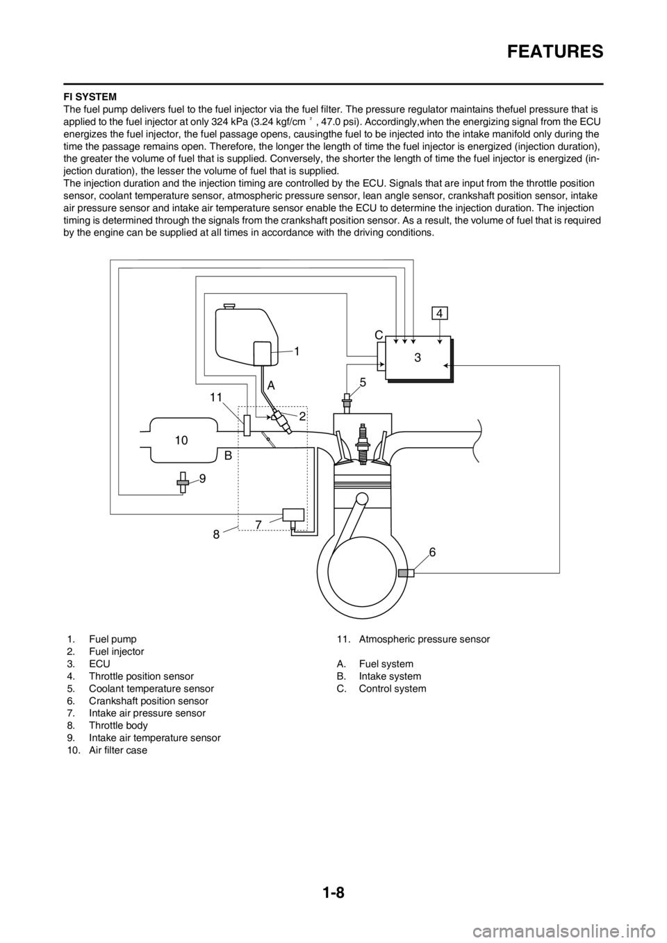
The fuel pump delivers fuel to the fuel injector via the fuel filter. The pressure regulator maintains thefuel pressure that is
applied to the fuel injector at only 324 kPa (3.24 kgf/cm², 47.0 psi). Accordingly,when the energizing signal from the ECU
energizes the fuel injector, the fuel passage opens, causingthe fuel to be injected into the intake manifold only during the
time the passage remains open. Therefore, the longer the length of time the fuel injector is energized (injection duration),
the greater the volume of fuel that is supplied. Conversely, the shorter the length of time the fuel injector is energized (in-
jection duration), the lesser the volume of fuel that is supplied.
The injection duration and the injection timing are controlled by the ECU. Signals that are input from the throttle position
sensor, coolant temperature sensor, atmospheric pressure sensor, lean angle sensor, crankshaft position sensor, intake
air pressure sensor and intake air temperature sensor enable the ECU to determine the injection duration. The injection
timing is determined through the signals from the crankshaft position sensor. As a result, the volume of fuel that is required
by the engine can be supplied at all times in accordance with the driving conditions.
1. Fuel pump
2. Fuel injector
3. ECU
4. Throttle position sensor
5. Coolant temperature sensor
6. Crankshaft position sensor
7. Intake air pressure sensor
8. Throttle body
9. Intake air temperature sensor
10. Air filter case11. Atmospheric pressure sensor
A. Fuel system
B. Intake system
C. Control system
1
10
9B
87
6 5
A
23 C4
11
Page 28 of 228
1-18
STARTING AND BREAK-IN
• Unlike a two-stroke engine, this
engine cannot be kick started
when the throttle is open be-
cause the kickstarter may kick
back. Also, if the throttle is open
the air/fuel mixture may be too
lean for the engine to start.
• Before starting the machine, per-
form the checks in the pre-opera-
tion check list.
AIR FILTER MAINTENANCE
According to "CLEANING THE AIR
FILTER ELEMENT" section in the
CHAPTER 3, apply the foam-air-filter
oil or its equivalent to the element.
(Excess oil in the element may ad-
versely affect engine starting.)
STARTING A COLD ENGINE
1. Inspect the coolant level.
2. Shift the transmission into neutral.
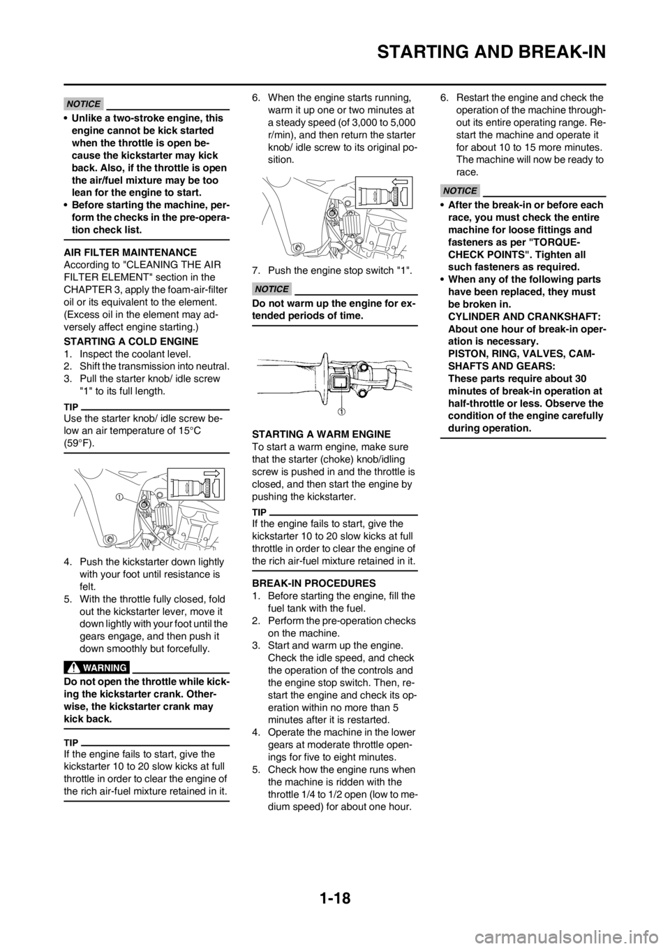
3. Pull the starter knob/ idle screw
"1" to its full length.
Use the starter knob/ idle screw be-
low an air temperature of 15°C
(59°F).
4. Push the kickstarter down lightly
with your foot until resistance is
felt.
5. With the throttle fully closed, fold
out the kickstarter lever, move it
down lightly with your foot until the
gears engage, and then push it
down smoothly but forcefully.
Do not open the throttle while kick-
ing the kickstarter crank. Other-
wise, the kickstarter crank may
kick back.
If the engine fails to start, give the
kickstarter 10 to 20 slow kicks at full
throttle in order to clear the engine of
the rich air-fuel mixture retained in it.
6. When the engine starts running,
warm it up one or two minutes at
a steady speed (of 3,000 to 5,000
r/min), and then return the starter
knob/ idle screw to its original po-
sition.
7. Push the engine stop switch "1".
Do not warm up the engine for ex-
tended periods of time.
STARTING A WARM ENGINE
To start a warm engine, make sure
that the starter (choke) knob/idling
screw is pushed in and the throttle is
closed, and then start the engine by
pushing the kickstarter.
If the engine fails to start, give the
kickstarter 10 to 20 slow kicks at full
throttle in order to clear the engine of
the rich air-fuel mixture retained in it.
BREAK-IN PROCEDURES
1. Before starting the engine, fill the
fuel tank with the fuel.
2. Perform the pre-operation checks
on the machine.
3. Start and warm up the engine.
Check the idle speed, and check
the operation of the controls and
the engine stop switch. Then, re-
start the engine and check its op-
eration within no more than 5
minutes after it is restarted.
4. Operate the machine in the lower
gears at moderate throttle open-
ings for five to eight minutes.
5. Check how the engine runs when
the machine is ridden with the
throttle 1/4 to 1/2 open (low to me-
dium speed) for about one hour.6. Restart the engine and check the
operation of the machine through-
out its entire operating range. Re-
start the machine and operate it
for about 10 to 15 more minutes.
The machine will now be ready to
race.
• After the break-in or before each
race, you must check the entire
machine for loose fittings and
fasteners as per "TORQUE-
CHECK POINTS". Tighten all
such fasteners as required.
• When any of the following parts
have been replaced, they must
be broken in.
CYLINDER AND CRANKSHAFT:
About one hour of break-in oper-
ation is necessary.
PISTON, RING, VALVES, CAM-
SHAFTS AND GEARS:
These parts require about 30
minutes of break-in operation at
half-throttle or less. Observe the
condition of the engine carefully
during operation.
Page 31 of 228
2-1
GENERAL SPECIFICATIONS
SPECIFICATIONS
GENERAL SPECIFICATIONS
Model name: YZ450FB (USA, CDN, AUS, NZ)
YZ450F (EUROPE, ZA)
Model code number: 33D9 (USA,CDN)
33DA (EUROPE)
33DC (AUS, NZ, ZA)
Dimensions: USA, CDN EUROPE AUS, NZ, ZA
Overall length 2,195 mm (86.42
in)2,191 mm (86.26
in)2,196 mm (86.46
in)
Overall width 825 mm (32.48 in)←←
Overall height 1,312 mm (51.65
in)1,311 mm (51.61
in)1,312 mm (51.65
in)
Seat height 999 mm (39.33 in)←998 mm (39.29 in)
Wheelbase 1,492 mm (58.74
in)1,487 mm (58.54
in)←
Minimum ground clearance 384 mm (15.12 in) 383 mm (15.08 in)←
Weight:
Curb weight 111 kg (245 lb)
Engine:
Engine type Liquid cooled 4-stroke, DOHC
Cylinder arrangement Single cylinder
Displacement 449.7 cm
3 (15.8 Imp oz, 15.2 US oz)
Bore × stroke 97.0 × 60.8 mm (3.82 × 2.39 in)
Compression ratio 12.5 : 1
Starting system Kickstarter
Lubrication system: Dry sump
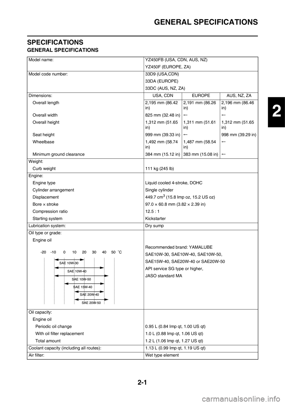
Oil type or grade:
Engine oil
Recommended brand: YAMALUBE
SAE10W-30, SAE10W-40, SAE10W-50,
SAE15W-40, SAE20W-40 or SAE20W-50
API service SG type or higher,
JASO standard MA
Oil capacity:
Engine oil
Periodic oil change 0.95 L (0.84 Imp qt, 1.00 US qt)
With oil filter replacement 1.0 L (0.88 Imp qt, 1.06 US qt)
Total amount 1.2 L (1.06 Imp qt, 1.27 US qt)
Coolant capacity (including all routes): 1.13 L (0.99 Imp qt, 1.19 US qt)
Air filter: Wet type element
2
Page 37 of 228
2-7
MAINTENANCE SPECIFICATIONS
Crankshaft:
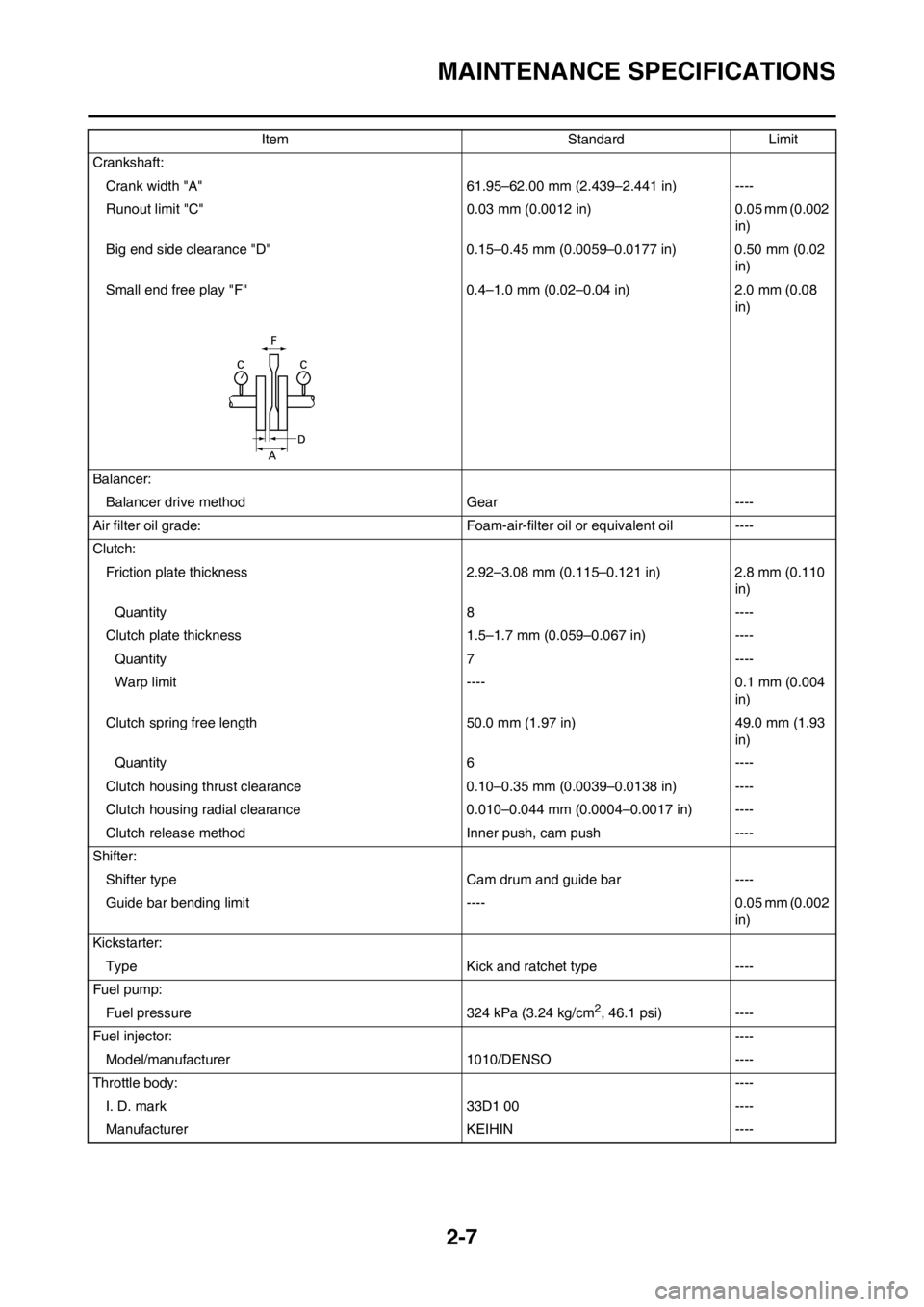
Crank width "A" 61.95–62.00 mm (2.439–2.441 in) ----
Runout limit "C" 0.03 mm (0.0012 in) 0.05 mm (0.002
in)
Big end side clearance "D" 0.15–0.45 mm (0.0059–0.0177 in) 0.50 mm (0.02
in)
Small end free play "F" 0.4–1.0 mm (0.02–0.04 in) 2.0 mm (0.08
in)
Balancer:
Balancer drive method Gear ----
Air filter oil grade: Foam-air-filter oil or equivalent oil ----
Clutch:
Friction plate thickness 2.92–3.08 mm (0.115–0.121 in) 2.8 mm (0.110
in)
Quantity 8 ----
Clutch plate thickness 1.5–1.7 mm (0.059–0.067 in) ----
Quantity 7 ----
Warp limit ---- 0.1 mm (0.004
in)
Clutch spring free length 50.0 mm (1.97 in) 49.0 mm (1.93
in)
Quantity 6 ----
Clutch housing thrust clearance 0.10–0.35 mm (0.0039–0.0138 in) ----
Clutch housing radial clearance 0.010–0.044 mm (0.0004–0.0017 in) ----
Clutch release method Inner push, cam push ----
Shifter:
Shifter type Cam drum and guide bar ----
Guide bar bending limit ---- 0.05 mm (0.002
in)
Kickstarter:
Type Kick and ratchet type ----
Fuel pump:
Fuel pressure 324 kPa (3.24 kg/cm
2, 46.1 psi) ----
Fuel injector:----
Model/manufacturer 1010/DENSO ----
Throttle body:----
I. D. mark 33D1 00 ----
Manufacturer KEIHIN ----Item Standard Limit
Page 38 of 228

2-8
MAINTENANCE SPECIFICATIONS
Throttle position sensor:----
Throttle position sensor maximum resistance 5 kΩ----
Throttle position sensor variable resistance 0–2 kΩ (full closed) ----
Throttle position sensor input voltage 4–6 V ----
Fuel injection sensor:----
Crankshaft position sensor resistance 248–372 Ω----
Intake air pressure sensor output voltage 3.57–3.71 V at 101.3kPa (1.013 kg/cm
2,
14.41 psi)----
Atmospheric pressure sensor output voltage 3.57–3.71 V at 101.3kPa (1.013 kg/cm
2,
14.41 psi)----
Intake air temperature sensor 5.4–6.6 kΩat 0 °C (32 °F)
290–390 Ωat 80 °C (176 °F)----
Idling condition:----
Engine idle speed 1,900–2,100 r/min ----
Oil temperature 55–65 °C (131–149 °F) ----
Lubrication system:
Oil filter type Paper type ----
Oil pump type Trochoid type ----
Tip clearance 0.12 mm or less (0.0047 in or less) 0.20 mm (0.008
in)
Side clearance 0.09–0.17 mm (0.0035–0.0067 in) 0.24 mm (0.009
in)
Housing and rotor clearance 0.03–0.10 mm (0.0012–0.0039 in) 0.17 mm (0.007
in)
Bypass valve setting pressure 40–80 kPa (0.4–0.8 kg/cm
2, 5.69–11.38
psi)----
Cooling:
Radiator core size
Width 121.4 mm (4.78 in) ----
Height 235 mm (9.25 in) ----
Thickness 28 mm (1.10 in) ----
Radiator cap opening pressure 108–137 kPa (1.08–1.37 kg/cm
2,
15.4–19.5 psi)----
Radiator capacity (total) 0.62 L (0.55 Imp qt, 0.66 US qt) ----
Water pump
Type Single-suction centrifugal pump ----Item Standard Limit
Page 41 of 228
2-11
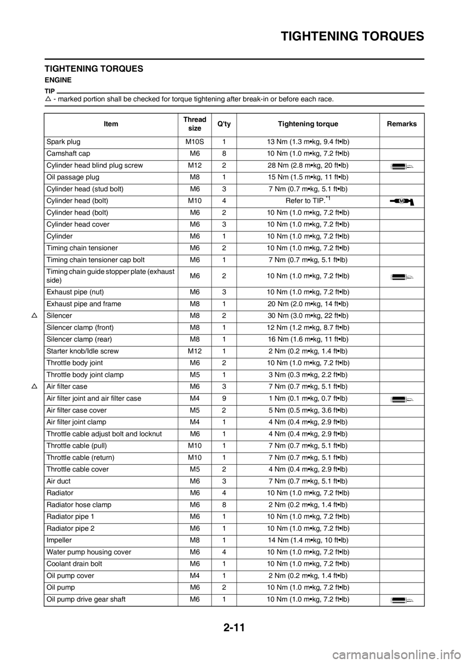
TIGHTENING TORQUES
TIGHTENING TORQUES
ENGINE
△- marked portion shall be checked for torque tightening after break-in or before each race.
ItemThread
sizeQ'ty Tightening torque Remarks
Spark plug M10S 1 13 Nm (1.3 m•kg, 9.4 ft•lb)
Camshaft cap M6 8 10 Nm (1.0 m•kg, 7.2 ft•lb)
Cylinder head blind plug screw M12 2 28 Nm (2.8 m•kg, 20 ft•lb)
Oil passage plug M8 1 15 Nm (1.5 m•kg, 11 ft•lb)
Cylinder head (stud bolt) M6 3 7 Nm (0.7 m•kg, 5.1 ft•lb)
Cylinder head (bolt) M10 4 Refer to TIP.
*1
Cylinder head (bolt) M6 2 10 Nm (1.0 m•kg, 7.2 ft•lb)
Cylinder head cover M6 3 10 Nm (1.0 m•kg, 7.2 ft•lb)
Cylinder M6 1 10 Nm (1.0 m•kg, 7.2 ft•lb)
Timing chain tensioner M6 2 10 Nm (1.0 m•kg, 7.2 ft•lb)
Timing chain tensioner cap bolt M6 1 7 Nm (0.7 m•kg, 5.1 ft•lb)
Timing chain guide stopper plate (exhaust
side)M6 2 10 Nm (1.0 m•kg, 7.2 ft•lb)
Exhaust pipe (nut) M6 3 10 Nm (1.0 m•kg, 7.2 ft•lb)
Exhaust pipe and frame M8 1 20 Nm (2.0 m•kg, 14 ft•lb)
△Silencer M8 2 30 Nm (3.0 m•kg, 22 ft•lb)
Silencer clamp (front) M8 1 12 Nm (1.2 m•kg, 8.7 ft•lb)
Silencer clamp (rear) M8 1 16 Nm (1.6 m•kg, 11 ft•lb)
Starter knob/Idle screw M12 1 2 Nm (0.2 m•kg, 1.4 ft•lb)
Throttle body joint M6 2 10 Nm (1.0 m•kg, 7.2 ft•lb)
Throttle body joint clamp M5 1 3 Nm (0.3 m•kg, 2.2 ft•lb)
△Air filter case M6 3 7 Nm (0.7 m•kg, 5.1 ft•lb)
Air filter joint and air filter case M4 9 1 Nm (0.1 m•kg, 0.7 ft•lb)
Air filter case cover M5 2 5 Nm (0.5 m•kg, 3.6 ft•lb)
Air filter joint clamp M4 1 4 Nm (0.4 m•kg, 2.9 ft•lb)
Throttle cable adjust bolt and locknut M6 1 4 Nm (0.4 m•kg, 2.9 ft•lb)
Throttle cable (pull) M10 1 7 Nm (0.7 m•kg, 5.1 ft•lb)
Throttle cable (return) M10 1 7 Nm (0.7 m•kg, 5.1 ft•lb)
Throttle cable cover M5 2 4 Nm (0.4 m•kg, 2.9 ft•lb)
Air duct M6 3 7 Nm (0.7 m•kg, 5.1 ft•lb)
Radiator M6 4 10 Nm (1.0 m•kg, 7.2 ft•lb)
Radiator hose clamp M6 8 2 Nm (0.2 m•kg, 1.4 ft•lb)
Radiator pipe 1 M6 1 10 Nm (1.0 m•kg, 7.2 ft•lb)
Radiator pipe 2 M6 1 10 Nm (1.0 m•kg, 7.2 ft•lb)
Impeller M8 1 14 Nm (1.4 m•kg, 10 ft•lb)
Water pump housing cover M6 4 10 Nm (1.0 m•kg, 7.2 ft•lb)
Coolant drain bolt M6 1 10 Nm (1.0 m•kg, 7.2 ft•lb)
Oil pump cover M4 1 2 Nm (0.2 m•kg, 1.4 ft•lb)
Oil pump M6 2 10 Nm (1.0 m•kg, 7.2 ft•lb)
Oil pump drive gear shaft M6 1 10 Nm (1.0 m•kg, 7.2 ft•lb)
Page 54 of 228
2-24
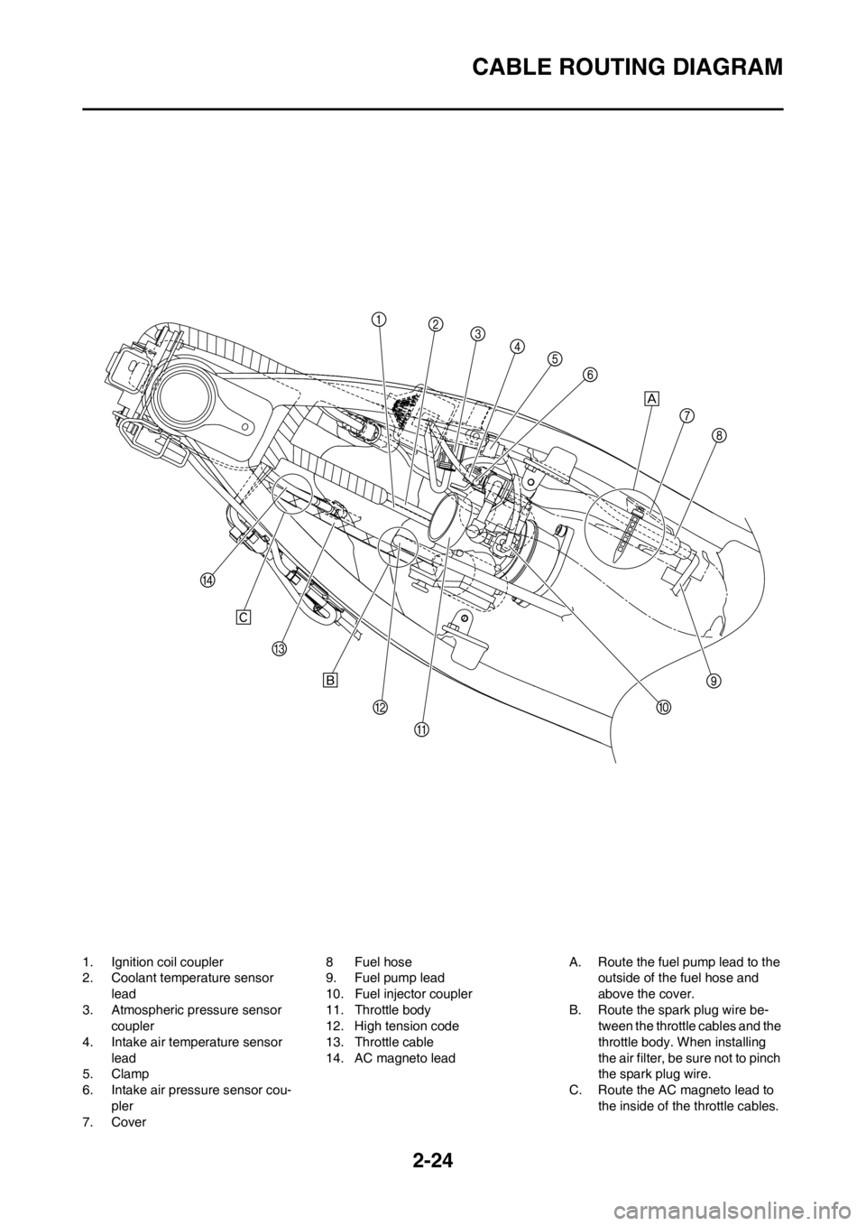
CABLE ROUTING DIAGRAM
1. Ignition coil coupler
2. Coolant temperature sensor
lead
3. Atmospheric pressure sensor
coupler
4. Intake air temperature sensor
lead
5. Clamp
6. Intake air pressure sensor cou-
pler
7. Cover8Fuel hose
9. Fuel pump lead
10. Fuel injector coupler
11. Throttle body
12. High tension code
13. Throttle cable
14. AC magneto leadA. Route the fuel pump lead to the
outside of the fuel hose and
above the cover.
B. Route the spark plug wire be-
tween the throttle cables and the
throttle body. When installing
the air filter, be sure not to pinch
the spark plug wire.
C. Route the AC magneto lead to
the inside of the throttle cables.
Page 59 of 228

3-3
MAINTENANCE INTERVALS
AIR FILTER
Clean and lubricate●●Use foam air-filter oil or equivalent oil.
Replace●
OIL FILTER
Replace●●
ENGINE GUARD
Replace●Breakage
FRAME
Clean and inspect●●
FUEL TANK, FUEL PUMP
inspect●●
FUEL HOSE
Inspect●
Replace●Every four years
BRAKES
Adjust lever position and pedal
height●●
Lubricate pivot point●●
Check brake disc surface●●
Check fluid level and leakage●●
Retighten brake disc bolts, cali-
per bolts, master cylinder bolts
and union bolts●●
Replace pads●
Replace brake fluid●Every one year
FRONT FORKS
Inspect and adjust●●
Replace oil●●Suspension oil "S1"
Replace oil seal●
FRONT FORK OIL SEAL AND
DUST SEAL
Clean and lube●●Lithium base grease
PROTECTOR GUIDE
Replace●
REAR SHOCK ABSORBER
Inspect and adjust●●
Lube●(After
rain
ride)●Molybdenum disulfide grease
Retighten●●
DRIVE CHAIN GUIDE AND
ROLLERS
Inspect●● ItemAfter
break-
inEvery
race
(about
2.5
hours)
Every
third
(about
7.5
hours)Every
fifth
(about
12.5
hours)
As re-
quiredRemarks
Page 64 of 228
3-8
ENGINE
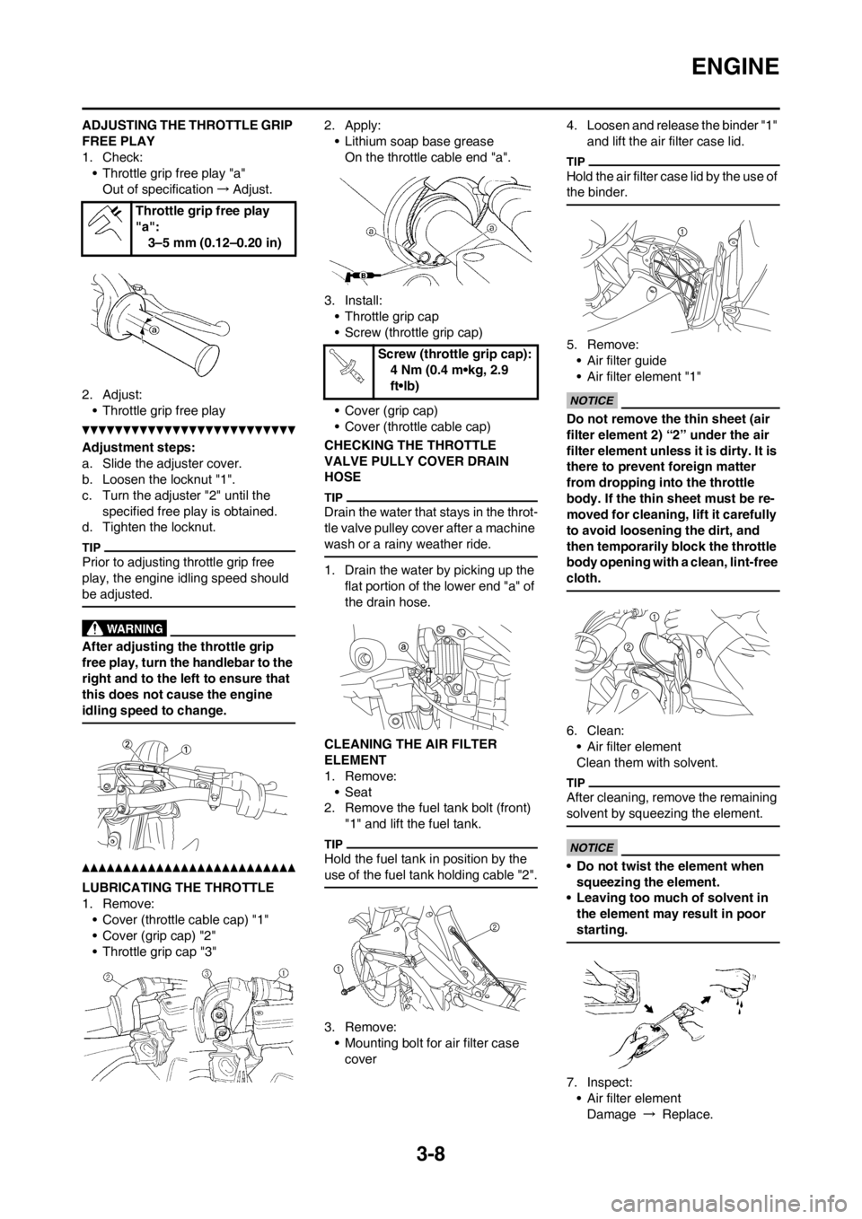
ADJUSTING THE THROTTLE GRIP
FREE PLAY
1. Check:
• Throttle grip free play "a"
Out of specification→Adjust.
2. Adjust:
• Throttle grip free play
Adjustment steps:
a. Slide the adjuster cover.
b. Loosen the locknut "1".
c. Turn the adjuster "2" until the
specified free play is obtained.
d. Tighten the locknut.
Prior to adjusting throttle grip free
play, the engine idling speed should
be adjusted.
After adjusting the throttle grip
free play, turn the handlebar to the
right and to the left to ensure that
this does not cause the engine
idling speed to change.
LUBRICATING THE THROTTLE
1. Remove:
• Cover (throttle cable cap) "1"
• Cover (grip cap) "2"
• Throttle grip cap "3"2. Apply:
• Lithium soap base grease
On the throttle cable end "a".
3. Install:
• Throttle grip cap
• Screw (throttle grip cap)
• Cover (grip cap)
• Cover (throttle cable cap)
CHECKING THE THROTTLE
VALVE PULLY COVER DRAIN
HOSE
Drain the water that stays in the throt-
tle valve pulley cover after a machine
wash or a rainy weather ride.
1. Drain the water by picking up the
flat portion of the lower end "a" of
the drain hose.
CLEANING THE AIR FILTER
ELEMENT
1. Remove:
•Seat
2. Remove the fuel tank bolt (front)
"1" and lift the fuel tank.
Hold the fuel tank in position by the
use of the fuel tank holding cable "2".
3. Remove:
• Mounting bolt for air filter case
cover4. Loosen and release the binder "1"
and lift the air filter case lid.
Hold the air filter case lid by the use of
the binder.
5. Remove:
• Air filter guide
• Air filter element "1"
Do not remove the thin sheet (air
filter element 2) “2” under the air
filter element unless it is dirty. It is
there to prevent foreign matter
from dropping into the throttle
body. If the thin sheet must be re-
moved for cleaning, lift it carefully
to avoid loosening the dirt, and
then temporarily block the throttle
body opening with a clean, lint-free
cloth.
6. Clean:
• Air filter element
Clean them with solvent.
After cleaning, remove the remaining
solvent by squeezing the element.
• Do not twist the element when
squeezing the element.
• Leaving too much of solvent in
the element may result in poor
starting.
7. Inspect:
• Air filter element
Damage → Replace. Throttle grip free play
"a":
3–5 mm (0.12–0.20 in)
Screw (throttle grip cap):
4 Nm (0.4 m•kg, 2.9
ft•lb)
Page 65 of 228
3-9
ENGINE
8. Apply:
• Foam-air-filter oil or equivalent oil
to the element
Squeeze out the excess oil. Element
should be wet but not dripping.
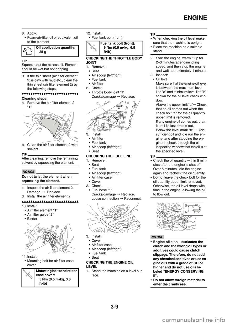
9. If the thin sheet (air filter element
2) is dirty with mud etc., clean the
thin sheet (air filter element 2) by
the following steps.
Cleaning steps:
a. Remove the air filter element 2
"1".
b. Clean the air filter element 2 with
solvent.
After cleaning, remove the remaining
solvent by squeezing the element.
Do not twist the element when
squeezing the element.
c. Inspect the air filter element 2.
Damage → Replace.
d. Install the air filter element 2.
10. Install:
• Air filter element "1"
• Air filter guide "2"
•Binder
11. Install:
• Mounting bolt for air filter case
cover12. Install:
• Fuel tank bolt (front)
CHECKING THE THROTTLE BODY
JOINT
1. Remove:
•Seat
• Air scoop (left/right)
•Fuel tank
• Air filter
2. Check:
• Throttle body joint "1"
Cracks/damage → Replace.
3. Install:
• Air filter
•Fuel tank
• Air scoop (left/right)
•Seat
CHECKING THE FUEL LINE
1. Remove:
•Seat
•Fuel tank
• Air scoop (left/right)
• Air filter case
• Cover
2. Check:
• Fuel hose "1"
Cracks/damage → Replace.
Loose connection → Reconnect.
3. Install:
• Cover
• Air filter case
• Air scoop (left/right)
•Fuel tank
•Seat
CHECKING THE ENGINE OIL
LEVEL
1. Stand the machine on a level sur-
face.
• When checking the oil level make
sure that the machine is upright.
• Place the machine on a suitable
stand.
2. Start the engine, warm it up for
2–3 minutes at engine idling
speed, and then stop the engine
and wait approximately 1 minute.
3. Inspect:
• Oil level
Make sure that the engine oil level
is between the maximum level
line "a" and minimum level line "b"
shown for the oil level check win-
dow.
Above the upper limit "a"→Check
that no oil comes out when the
check bolt "1" for the oil quantity
upper limit is removed.
If any engine oil comes out, drain
it until its last drop is out.
Below the level mark "b"→Add
sufficient oil and idle run the en-
gine, and after stopping the en-
gine, recheck through the oil
inspection window that the oil is at
the specified level.
• Check the oil quantity within 5 min-
utes after the engine is shut off.
Over 5 minutes, idle the engine
again and recheck the oil quantity.
• Do not leave the check bolt for the
oil quantity upper limit removed.
Otherwise, the oil level drops with
time in the engine, allowing the oil
to flow out.
• Engine oil also luburicates the
clutch and the wrong oil types or
additives could cause clutch
slippage. Therefore, do not add
any chemical additives or use en-
gine oils with a grade of CD or
higher and do not use oils la-
beled "ENERGY CONSERVING
II".
• Do not allow foreign material to
enter the crankcase.
Oil application quantify:
35 g
Mounting bolt for air filter
case cover:
5 Nm (0.5 m•kg, 3.6
ft•lb)
Fuel tank bolt (front):
9 Nm (0.9 m•kg, 6.5
ft•lb)