checking oil YAMAHA YZ450F 2013 Owners Manual
[x] Cancel search | Manufacturer: YAMAHA, Model Year: 2013, Model line: YZ450F, Model: YAMAHA YZ450F 2013Pages: 228, PDF Size: 11.41 MB
Page 10 of 228

CONTENTS
CHAPTER 1
GENERAL INFOR-
MATION
LOCATION OF
IMPORTANT LABELS ..... 1-1
DESCRIPTION ................. 1-5
CONSUMER
INFORMATION................. 1-6
FEATURES....................... 1-7
INCLUDED PARTS .......... 1-9
IMPORTANT
INFORMATION................. 1-9
HANDLING THE
ELECTRONIC PARTS ... 1-10
CHECKING OF
CONNECTION ................ 1-10
SPECIAL TOOLS ........... 1-12
CONTROL
FUNCTIONS ................... 1-17
STARTING
AND BREAK-IN.............. 1-17
TORQUE-CHECK
POINTS........................... 1-19
CLEANING
AND STORAGE ............. 1-20
CHAPTER 2
SPECIFICATIONS
GENERAL
SPECIFICATIONS ............ 2-1
MAINTENANCE
SPECIFICATIONS ............ 2-3
TIGHTENING
TORQUES ...................... 2-11
LUBRICATION
DIAGRAMS .................... 2-17
CABLE ROUTING
DIAGRAM ....................... 2-18
CHAPTER 3
REGULAR INSPEC-
TION AND AD-
JUSTMENTS
MAINTENANCE
INTERVALS ...................... 3-1
PRE-OPERATION
INSPECTION
AND MAINTENANCE ....... 3-5
ENGINE ............................ 3-6
CHASSIS ........................ 3-14
ELECTRICAL ................. 3-24
CHAPTER 4
ENGINE
SEAT
AND SIDE COVERS ......... 4-1
EXHAUST PIPE
AND SILENCER ............... 4-3
RADIATOR ....................... 4-5
CAMSHAFTS.................... 4-8
CYLINDER HEAD........... 4-13
VALVES AND
VALVE SPRINGS ........... 4-17
CYLINDER
AND PISTON .................. 4-21
CLUTCH ......................... 4-25
OIL FILTER ELEMENT
AND WATER PUMP ....... 4-29
BALANCER .................... 4-33
OIL PUMP ....................... 4-35
KICK SHAFT
AND SHIFT SHAFT ........ 4-38
AC MAGNETO................ 4-43
ENGINE REMOVAL ....... 4-45
CRANKCASE
AND CRANKSHAFT ...... 4-50
TRANSMISSION,
SHIFT CAM
AND SHIFT FORK .......... 4-56
CHAPTER 5
CHASSIS
FRONT WHEEL
AND REAR WHEEL .........5-1
FRONT BRAKE
AND REAR BRAKE..........5-6
FRONT FORK .................5-16
HANDLEBAR..................5-24
STEERING ......................5-28
SWINGARM ....................5-32
REAR
SHOCK ABSORBER ......5-37
CHAPTER 6
FUEL SYSTEM
FUEL TANK ......................6-1
THROTTLE BODY ............6-4
CHAPTER 7
ELECTRICAL
ELECTRICAL
COMPONENTS AND
WIRING DIAGRAM ...........7-1
IGNITION SYSTEM...........7-3
THROTTLE POSITION
SENSOR SYSTEM ...........7-6
FUEL INJECTION
SYSTEM............................7-9
FUEL PUMP SYSTEM ....7-35
ELECTRICAL
COMPONENTS...............7-36
CHAPTER 8
TUNING
CHASSIS ..........................8-1
Page 20 of 228
1-10
HANDLING THE ELECTRONIC PARTS
4. During the machine disassembly,
clean all parts and place them in
trays in the order of disassembly.
This will speed up assembly time
and help assure that all parts are
correctly reinstalled.
5. Keep away from fire.
ALL REPLACEMENT PARTS
1. We recommend to use Yamaha
genuine parts for all replace-
ments. Use oil and/or grease rec-
ommended by Yamaha for
assembly and adjustment.
GASKETS, OIL SEALS AND O-
RINGS
1. All gaskets, oil seals, and O-rings
should be replaced when an en-
gine is overhauled. All gasket sur-
faces, oil seal lips, and O-rings
must be cleaned.
2. Properly oil all mating parts and
bearings during reassembly. Ap-
ply grease to the oil seal lips.
LOCK WASHERS/PLATES AND
COTTER PINS
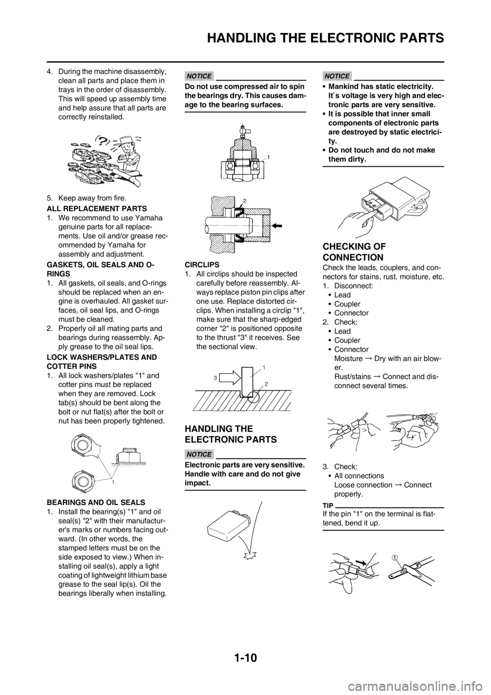
1. All lock washers/plates "1" and
cotter pins must be replaced
when they are removed. Lock
tab(s) should be bent along the
bolt or nut flat(s) after the bolt or
nut has been properly tightened.
BEARINGS AND OIL SEALS
1. Install the bearing(s) "1" and oil
seal(s) "2" with their manufactur-
er's marks or numbers facing out-
ward. (In other words, the
stamped letters must be on the
side exposed to view.) When in-
stalling oil seal(s), apply a light
coating of lightweight lithium base
grease to the seal lip(s). Oil the
bearings liberally when installing.
Do not use compressed air to spin
the bearings dry. This causes dam-
age to the bearing surfaces.
CIRCLIPS
1. All circlips should be inspected
carefully before reassembly. Al-
ways replace piston pin clips after
one use. Replace distorted cir-
clips. When installing a circlip "1",
make sure that the sharp-edged
corner "2" is positioned opposite
to the thrust "3" it receives. See
the sectional view.
HANDLING THE
ELECTRONIC PARTS
Electronic parts are very sensitive.
Handle with care and do not give
impact.
• Mankind has static electricity.
It`s voltage is very high and elec-
tronic parts are very sensitive.
• It is possible that inner small
components of electronic parts
are destroyed by static electrici-
ty.
• Do not touch and do not make
them dirty.
CHECKING OF
CONNECTION
Check the leads, couplers, and con-
nectors for stains, rust, moisture, etc.
1. Disconnect:
•Lead
• Coupler
• Connector
2. Check:
•Lead
• Coupler
• Connector
Moisture → Dry with an air blow-
er.
Rust/stains → Connect and dis-
connect several times.
3. Check:
• All connections
Loose connection → Connect
properly.
If the pin "1" on the terminal is flat-
tened, bend it up.
Page 23 of 228
1-13
SPECIAL TOOLS
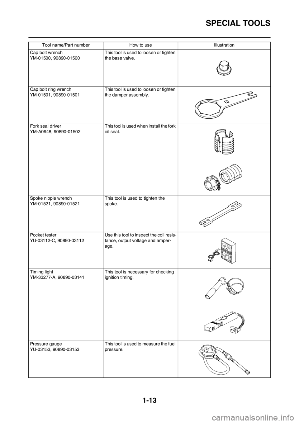
Cap bolt wrench
YM-01500, 90890-01500This tool is used to loosen or tighten
the base valve.
Cap bolt ring wrench
YM-01501, 90890-01501This tool is used to loosen or tighten
the damper assembly.
Fork seal driver
YM-A0948, 90890-01502 This tool is used when install the fork
oil seal.
Spoke nipple wrench
YM-01521, 90890-01521 This tool is used to tighten the
spoke.
Pocket tester
YU-03112-C, 90890-03112 Use this tool to inspect the coil resis-
tance, output voltage and amper-
age.
Timing light
YM-33277-A, 90890-03141 This tool is necessary for checking
ignition timing.
Pressure gauge
YU-03153, 90890-03153 This tool is used to measure the fuel
pressure. Tool name/Part number How to use Illustration
Page 62 of 228
3-6
ENGINE
ENGINE
CHECKING THE COOLANT LEVEL
Do not remove the radiator cap
"1", drain bolt and hoses when the
engine and radiator are hot. Scald-
ing hot fluid and steam may be
blown out under pressure, which
could cause serious injury. When
the engine has cooled, place a
thick towel over the radiator cap,
slowly rotate the cap counter-
clockwise to the detent. This pro-
cedure allows any residual
pressure to escape. When the
hissing sound has stopped, press
down on the cap while turning
counterclockwise and remove it.
Hard water or salt water is harmful
to the engine parts. You may use
distilled water, if you can't get soft
water.
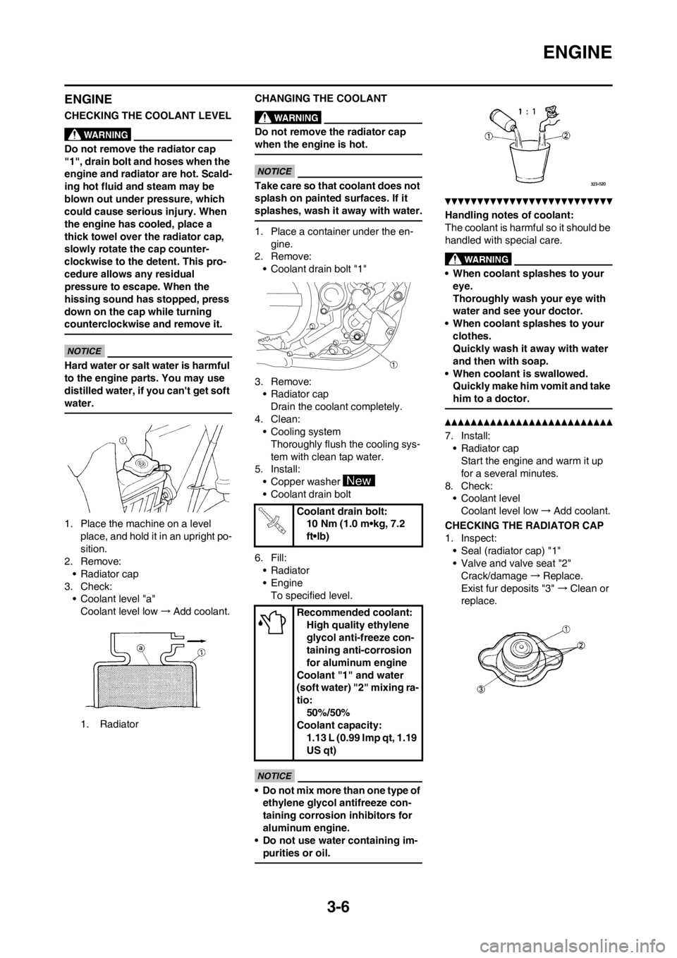
1. Place the machine on a level
place, and hold it in an upright po-
sition.
2. Remove:
• Radiator cap
3. Check:
• Coolant level "a"
Coolant level low→Add coolant.
1. RadiatorCHANGING THE COOLANT
Do not remove the radiator cap
when the engine is hot.
Take care so that coolant does not
splash on painted surfaces. If it
splashes, wash it away with water.
1. Place a container under the en-
gine.
2. Remove:
• Coolant drain bolt "1"
3. Remove:
• Radiator cap
Drain the coolant completely.
4. Clean:
• Cooling system
Thoroughly flush the cooling sys-
tem with clean tap water.
5. Install:
• Copper washer
• Coolant drain bolt
6. Fill:
• Radiator
•Engine
To specified level.
• Do not mix more than one type of
ethylene glycol antifreeze con-
taining corrosion inhibitors for
aluminum engine.
• Do not use water containing im-
purities or oil.
Handling notes of coolant:
The coolant is harmful so it should be
handled with special care.
• When coolant splashes to your
eye.
Thoroughly wash your eye with
water and see your doctor.
• When coolant splashes to your
clothes.
Quickly wash it away with water
and then with soap.
• When coolant is swallowed.
Quickly make him vomit and take
him to a doctor.
7. Install:
• Radiator cap
Start the engine and warm it up
for a several minutes.
8. Check:
• Coolant level
Coolant level low→Add coolant.
CHECKING THE RADIATOR CAP
1. Inspect:
• Seal (radiator cap) "1"
• Valve and valve seat "2"
Crack/damage→Replace.
Exist fur deposits "3" →Clean or
replace.
Coolant drain bolt:
10 Nm (1.0 m•kg, 7.2
ft•lb)
Recommended coolant:
High quality ethylene
glycol anti-freeze con-
taining anti-corrosion
for aluminum engine
Coolant "1" and water
(soft water) "2" mixing ra-
tio:
50%/50%
Coolant capacity:
1.13 L (0.99 Imp qt, 1.19
US qt)
Page 65 of 228
3-9
ENGINE
8. Apply:
• Foam-air-filter oil or equivalent oil
to the element
Squeeze out the excess oil. Element
should be wet but not dripping.
9. If the thin sheet (air filter element
2) is dirty with mud etc., clean the
thin sheet (air filter element 2) by
the following steps.
Cleaning steps:
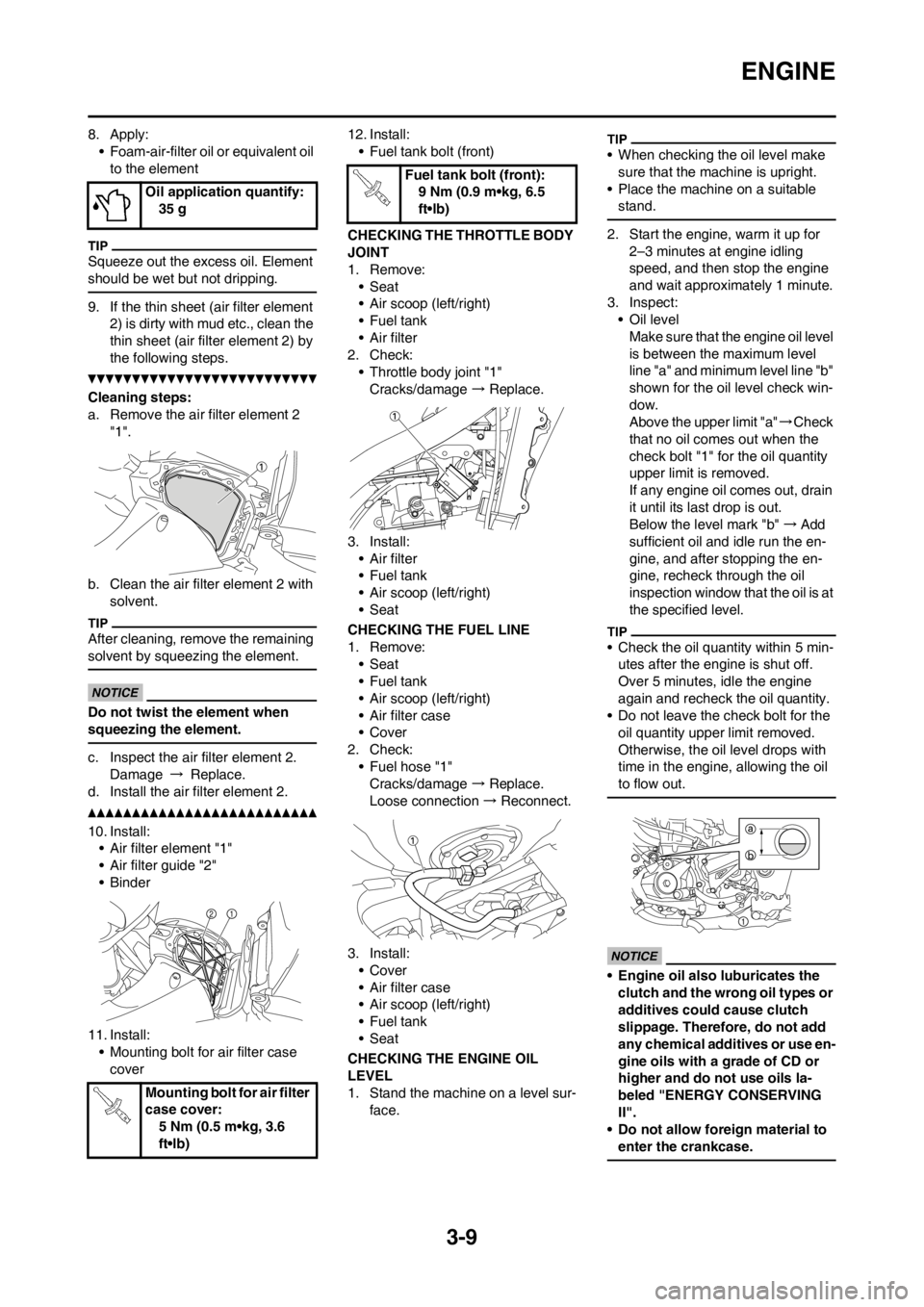
a. Remove the air filter element 2
"1".
b. Clean the air filter element 2 with
solvent.
After cleaning, remove the remaining
solvent by squeezing the element.
Do not twist the element when
squeezing the element.
c. Inspect the air filter element 2.
Damage → Replace.
d. Install the air filter element 2.
10. Install:
• Air filter element "1"
• Air filter guide "2"
•Binder
11. Install:
• Mounting bolt for air filter case
cover12. Install:
• Fuel tank bolt (front)
CHECKING THE THROTTLE BODY
JOINT
1. Remove:
•Seat
• Air scoop (left/right)
•Fuel tank
• Air filter
2. Check:
• Throttle body joint "1"
Cracks/damage → Replace.
3. Install:
• Air filter
•Fuel tank
• Air scoop (left/right)
•Seat
CHECKING THE FUEL LINE
1. Remove:
•Seat
•Fuel tank
• Air scoop (left/right)
• Air filter case
• Cover
2. Check:
• Fuel hose "1"
Cracks/damage → Replace.
Loose connection → Reconnect.
3. Install:
• Cover
• Air filter case
• Air scoop (left/right)
•Fuel tank
•Seat
CHECKING THE ENGINE OIL
LEVEL
1. Stand the machine on a level sur-
face.
• When checking the oil level make
sure that the machine is upright.
• Place the machine on a suitable
stand.
2. Start the engine, warm it up for
2–3 minutes at engine idling
speed, and then stop the engine
and wait approximately 1 minute.
3. Inspect:
• Oil level
Make sure that the engine oil level
is between the maximum level
line "a" and minimum level line "b"
shown for the oil level check win-
dow.
Above the upper limit "a"→Check
that no oil comes out when the
check bolt "1" for the oil quantity
upper limit is removed.
If any engine oil comes out, drain
it until its last drop is out.
Below the level mark "b"→Add
sufficient oil and idle run the en-
gine, and after stopping the en-
gine, recheck through the oil
inspection window that the oil is at
the specified level.
• Check the oil quantity within 5 min-
utes after the engine is shut off.
Over 5 minutes, idle the engine
again and recheck the oil quantity.
• Do not leave the check bolt for the
oil quantity upper limit removed.
Otherwise, the oil level drops with
time in the engine, allowing the oil
to flow out.
• Engine oil also luburicates the
clutch and the wrong oil types or
additives could cause clutch
slippage. Therefore, do not add
any chemical additives or use en-
gine oils with a grade of CD or
higher and do not use oils la-
beled "ENERGY CONSERVING
II".
• Do not allow foreign material to
enter the crankcase.
Oil application quantify:
35 g
Mounting bolt for air filter
case cover:
5 Nm (0.5 m•kg, 3.6
ft•lb)
Fuel tank bolt (front):
9 Nm (0.9 m•kg, 6.5
ft•lb)
Page 66 of 228
3-10
ENGINE
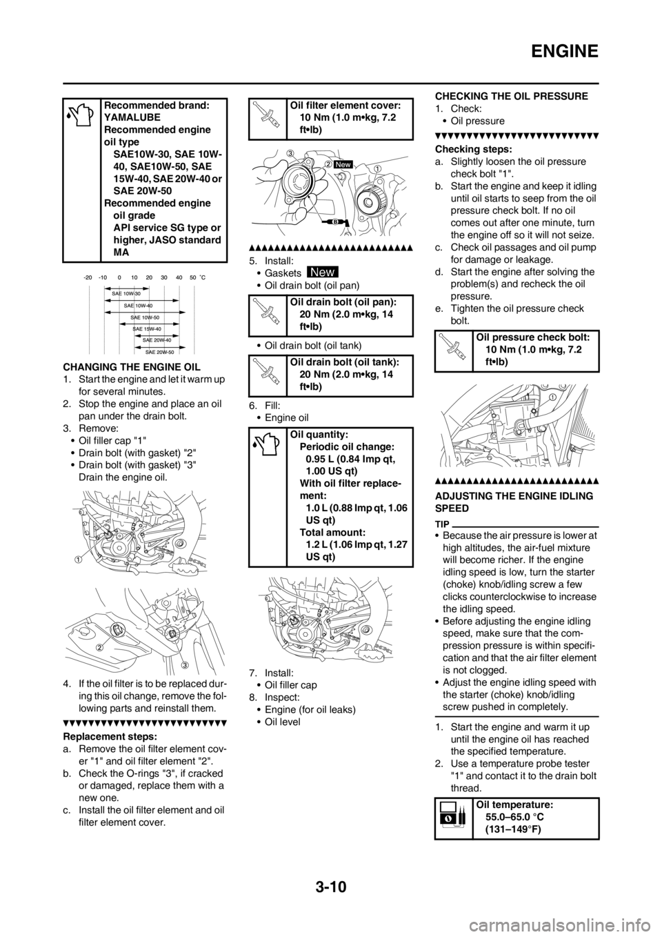
CHANGING THE ENGINE OIL
1. Start the engine and let it warm up
for several minutes.
2. Stop the engine and place an oil
pan under the drain bolt.
3. Remove:
• Oil filler cap "1"
• Drain bolt (with gasket) "2"
• Drain bolt (with gasket) "3"
Drain the engine oil.
4. If the oil filter is to be replaced dur-
ing this oil change, remove the fol-
lowing parts and reinstall them.
Replacement steps:
a. Remove the oil filter element cov-
er "1" and oil filter element "2".
b. Check the O-rings "3", if cracked
or damaged, replace them with a
new one.
c. Install the oil filter element and oil
filter element cover.
5. Install:
• Gaskets
• Oil drain bolt (oil pan)
• Oil drain bolt (oil tank)
6. Fill:
• Engine oil
7. Install:
• Oil filler cap
8. Inspect:
• Engine (for oil leaks)
• Oil levelCHECKING THE OIL PRESSURE
1. Check:
• Oil pressure
Checking steps:
a. Slightly loosen the oil pressure
check bolt "1".
b. Start the engine and keep it idling
until oil starts to seep from the oil
pressure check bolt. If no oil
comes out after one minute, turn
the engine off so it will not seize.
c. Check oil passages and oil pump
for damage or leakage.
d. Start the engine after solving the
problem(s) and recheck the oil
pressure.
e. Tighten the oil pressure check
bolt.
ADJUSTING THE ENGINE IDLING
SPEED
• Because the air pressure is lower at
high altitudes, the air-fuel mixture
will become richer. If the engine
idling speed is low, turn the starter
(choke) knob/idling screw a few
clicks counterclockwise to increase
the idling speed.
• Before adjusting the engine idling
speed, make sure that the com-
pression pressure is within specifi-
cation and that the air filter element
is not clogged.
• Adjust the engine idling speed with
the starter (choke) knob/idling
screw pushed in completely.
1. Start the engine and warm it up
until the engine oil has reached
the specified temperature.
2. Use a temperature probe tester
"1" and contact it to the drain bolt
thread. Recommended brand:
YAMALUBE
Recommended engine
oil type
SAE10W-30, SAE 10W-
40, SAE10W-50, SAE
15W-40, SAE 20W-40 or
SAE 20W-50
Recommended engine
oil grade
API service SG type or
higher, JASO standard
MA
Oil filter element cover:
10 Nm (1.0 m•kg, 7.2
ft•lb)
Oil drain bolt (oil pan):
20 Nm (2.0 m•kg, 14
ft•lb)
Oil drain bolt (oil tank):
20 Nm (2.0 m•kg, 14
ft•lb)
Oil quantity:
Periodic oil change:
0.95 L (0.84 Imp qt,
1.00 US qt)
With oil filter replace-
ment:
1.0 L (0.88 Imp qt, 1.06
US qt)
Total amount:
1.2 L (1.06 Imp qt, 1.27
US qt)
Oil pressure check bolt:
10 Nm (1.0 m•kg, 7.2
ft•lb)
Oil temperature:
55.0–65.0 °C
(131–149°F)
Page 67 of 228
3-11
ENGINE
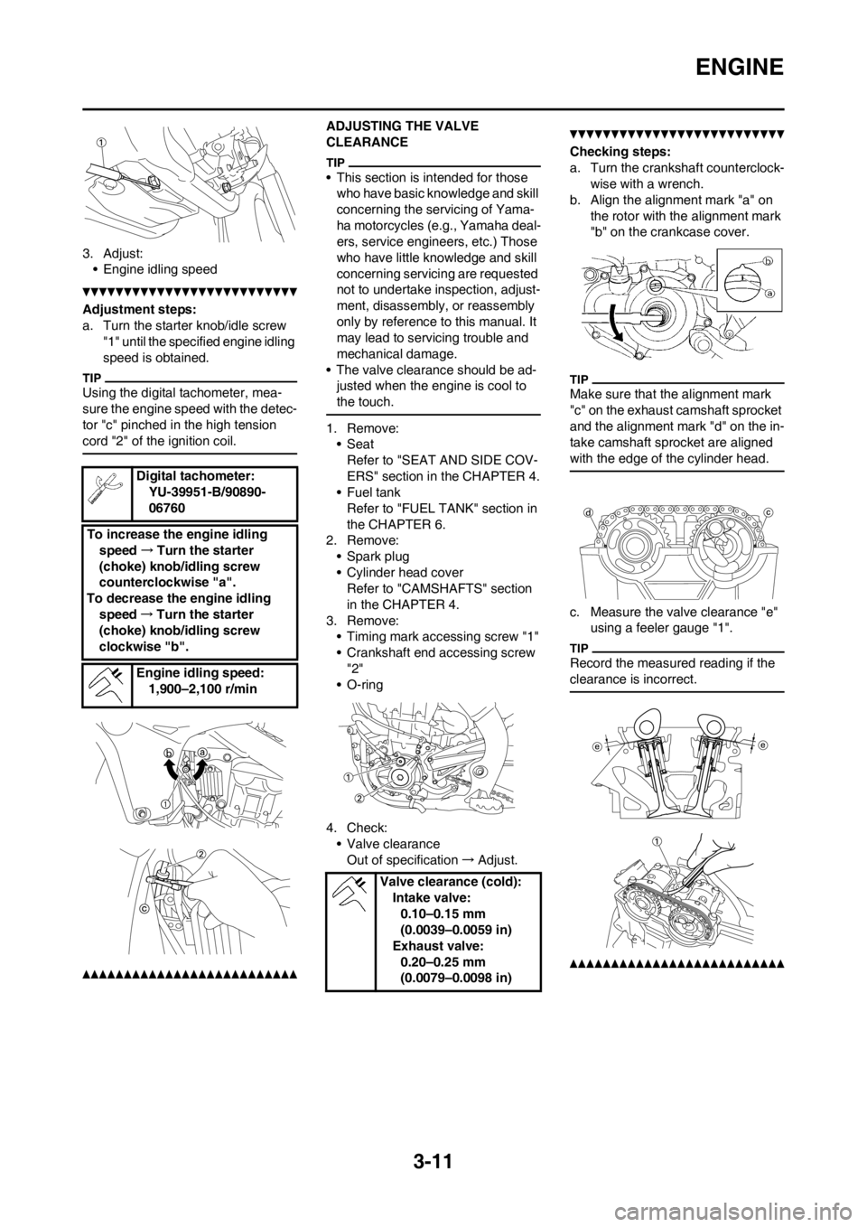
3. Adjust:
• Engine idling speed
Adjustment steps:
a. Turn the starter knob/idle screw
"1" until the specified engine idling
speed is obtained.
Using the digital tachometer, mea-
sure the engine speed with the detec-
tor "c" pinched in the high tension
cord "2" of the ignition coil.
ADJUSTING THE VALVE
CLEARANCE
• This section is intended for those
who have basic knowledge and skill
concerning the servicing of Yama-
ha motorcycles (e.g., Yamaha deal-
ers, service engineers, etc.) Those
who have little knowledge and skill
concerning servicing are requested
not to undertake inspection, adjust-
ment, disassembly, or reassembly
only by reference to this manual. It
may lead to servicing trouble and
mechanical damage.
• The valve clearance should be ad-
justed when the engine is cool to
the touch.
1. Remove:
•Seat
Refer to "SEAT AND SIDE COV-
ERS" section in the CHAPTER 4.
•Fuel tank
Refer to "FUEL TANK" section in
the CHAPTER 6.
2. Remove:
• Spark plug
• Cylinder head cover
Refer to "CAMSHAFTS" section
in the CHAPTER 4.
3. Remove:
• Timing mark accessing screw "1"
• Crankshaft end accessing screw
"2"
• O-ring
4. Check:
• Valve clearance
Out of specification→Adjust.
Checking steps:
a. Turn the crankshaft counterclock-
wise with a wrench.
b. Align the alignment mark "a" on
the rotor with the alignment mark
"b" on the crankcase cover.
Make sure that the alignment mark
"c" on the exhaust camshaft sprocket
and the alignment mark "d" on the in-
take camshaft sprocket are aligned
with the edge of the cylinder head.
c. Measure the valve clearance "e"
using a feeler gauge "1".
Record the measured reading if the
clearance is incorrect.
Digital tachometer:
YU-39951-B/90890-
06760
To increase the engine idling
speed→Turn the starter
(choke) knob/idling screw
counterclockwise "a".
To decrease the engine idling
speed→Turn the starter
(choke) knob/idling screw
clockwise "b".
Engine idling speed:
1,900–2,100 r/min
Valve clearance (cold):
Intake valve:
0.10–0.15 mm
(0.0039–0.0059 in)
Exhaust valve:
0.20–0.25 mm
(0.0079–0.0098 in)
Page 73 of 228
3-17
CHASSIS
a. Lower level
A. Front
B. Rear
CHECKING THE SPROCKET
1. Inspect:
• Sprocket teeth "a"
Excessive wear→Replace.
Replace the drive sprocket, rear
wheel sprocket and drive chain as a
set.
CHECKING THE DRIVE CHAIN
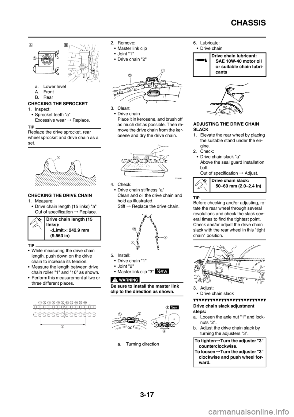
1. Measure:
• Drive chain length (15 links) "a"
Out of specification→Replace.
• While measuring the drive chain
length, push down on the drive
chain to increase its tension.
• Measure the length between drive
chain roller "1" and "16" as shown.
• Perform this measurement at two or
three different places.
2. Remove:
• Master link clip
•Joint "1"
• Drive chain "2"
3. Clean:
• Drive chain
Place it in kerosene, and brush off
as much dirt as possible. Then re-
move the drive chain from the ker-
osene and dry the drive chain.
4. Check:
• Drive chain stiffness "a"
Clean and oil the drive chain and
hold as illustrated.
Stiff→Replace the drive chain.
5. Install:
• Drive chain "1"
•Joint "2"
• Master link clip "3"
Be sure to install the master link
clip to the direction as shown.
a. Turning direction6. Lubricate:
• Drive chain
ADJUSTING THE DRIVE CHAIN
SLACK
1. Elevate the rear wheel by placing
the suitable stand under the en-
gine.
2. Check:
• Drive chain slack "a"
Above the seal guard installation
bolt.
Out of specification→Adjust.
Before checking and/or adjusting, ro-
tate the rear wheel through several
revolutions and check the slack sev-
eral times to find the tightest point.
Check and/or adjust the drive chain
slack with the rear wheel in this "tight
chain" position.
3. Adjust:
• Drive chain slack
Drive chain slack adjustment
steps:
a. Loosen the axle nut "1" and lock-
nuts "2".
b. Adjust the drive chain slack by
turning the adjusters "3". Drive chain length (15
links):
(9.563 in)
Drive chain lubricant:
SAE 10W-40 motor oil
or suitable chain lubri-
cants
Drive chain slack:
50–60 mm (2.0–2.4 in)
To tighten→Turn the adjuster "3"
counterclockwise.
To loosen→Turn the adjuster "3"
clockwise and push wheel for-
ward.
Page 74 of 228
3-18
CHASSIS
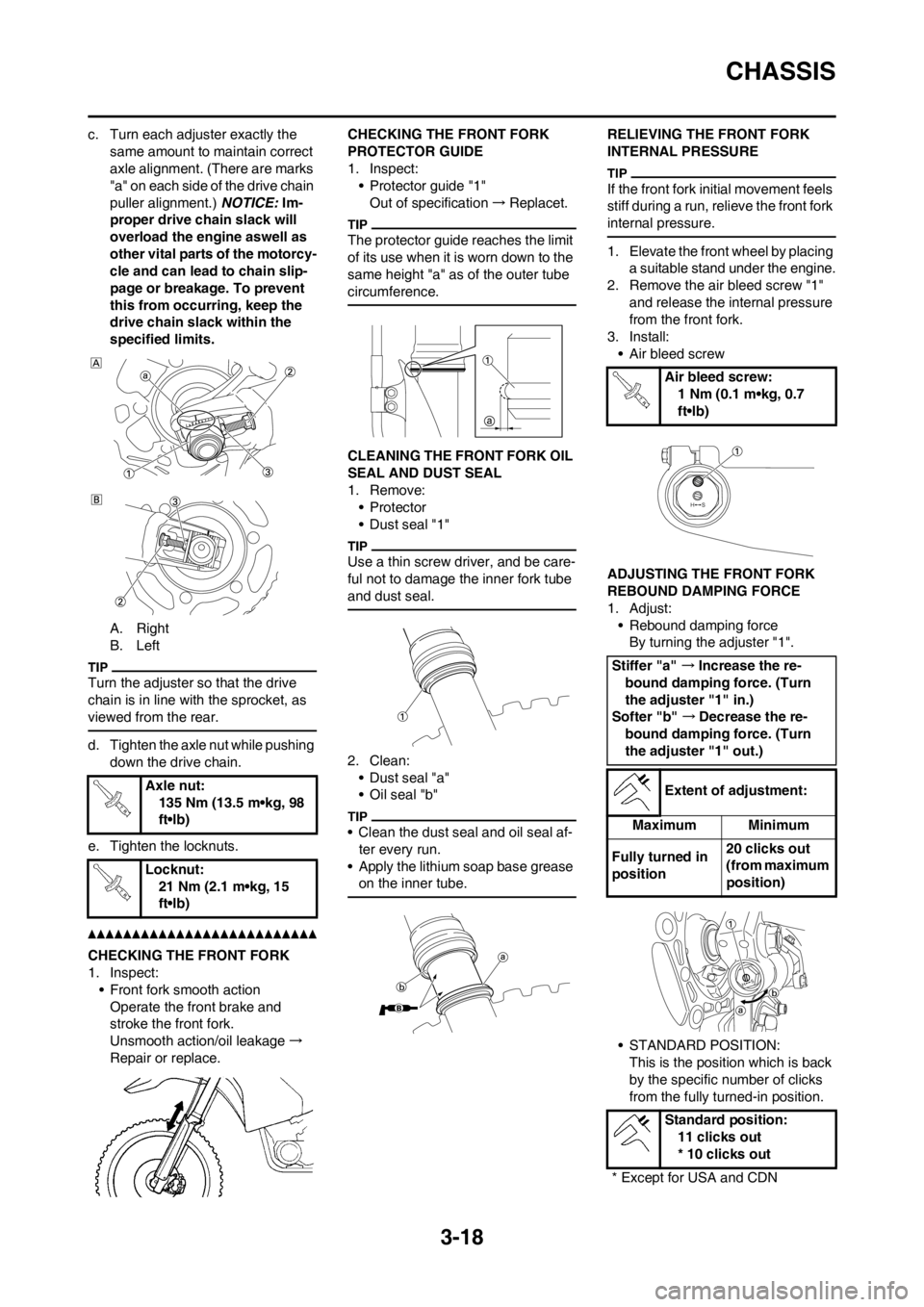
c. Turn each adjuster exactly the
same amount to maintain correct
axle alignment. (There are marks
"a" on each side of the drive chain
puller alignment.) NOTICE: Im-
proper drive chain slack will
overload the engine aswell as
other vital parts of the motorcy-
cle and can lead to chain slip-
page or breakage. To prevent
this from occurring, keep the
drive chain slack within the
specified limits.
A. Right
B. Left
Turn the adjuster so that the drive
chain is in line with the sprocket, as
viewed from the rear.
d. Tighten the axle nut while pushing
down the drive chain.
e. Tighten the locknuts.
CHECKING THE FRONT FORK
1. Inspect:
• Front fork smooth action
Operate the front brake and
stroke the front fork.
Unsmooth action/oil leakage→
Repair or replace.CHECKING THE FRONT FORK
PROTECTOR GUIDE
1. Inspect:
• Protector guide "1"
Out of specification→Replacet.
The protector guide reaches the limit
of its use when it is worn down to the
same height "a" as of the outer tube
circumference.
CLEANING THE FRONT FORK OIL
SEAL AND DUST SEAL
1. Remove:
•Protector
• Dust seal "1"
Use a thin screw driver, and be care-
ful not to damage the inner fork tube
and dust seal.
2. Clean:
• Dust seal "a"
• Oil seal "b"
• Clean the dust seal and oil seal af-
ter every run.
• Apply the lithium soap base grease
on the inner tube.
RELIEVING THE FRONT FORK
INTERNAL PRESSURE
If the front fork initial movement feels
stiff during a run, relieve the front fork
internal pressure.
1. Elevate the front wheel by placing
a suitable stand under the engine.
2. Remove the air bleed screw "1"
and release the internal pressure
from the front fork.
3. Install:
• Air bleed screw
ADJUSTING THE FRONT FORK
REBOUND DAMPING FORCE
1. Adjust:
• Rebound damping force
By turning the adjuster "1".
• STANDARD POSITION:
This is the position which is back
by the specific number of clicks
from the fully turned-in position. Axle nut:
135 Nm (13.5 m•kg, 98
ft•lb)
Locknut:
21 Nm (2.1 m•kg, 15
ft•lb)
Air bleed screw:
1 Nm (0.1 m•kg, 0.7
ft•lb)
Stiffer "a" →Increase the re-
bound damping force. (Turn
the adjuster "1" in.)
Softer "b" →Decrease the re-
bound damping force. (Turn
the adjuster "1" out.)
Extent of adjustment:
Maximum Minimum
Fully turned in
position20 clicks out
(from maximum
position)
Standard position:
11 clicks out
* 10 clicks out
* Except for USA and CDN
Page 75 of 228
3-19
CHASSIS
Do not force the adjuster past the
minimum or maximum extent of
adjustment. The adjuster may be
damaged.
Always adjust each front fork to
the same setting. Uneven adjust-
ment can cause poor handling and
loss of stability.
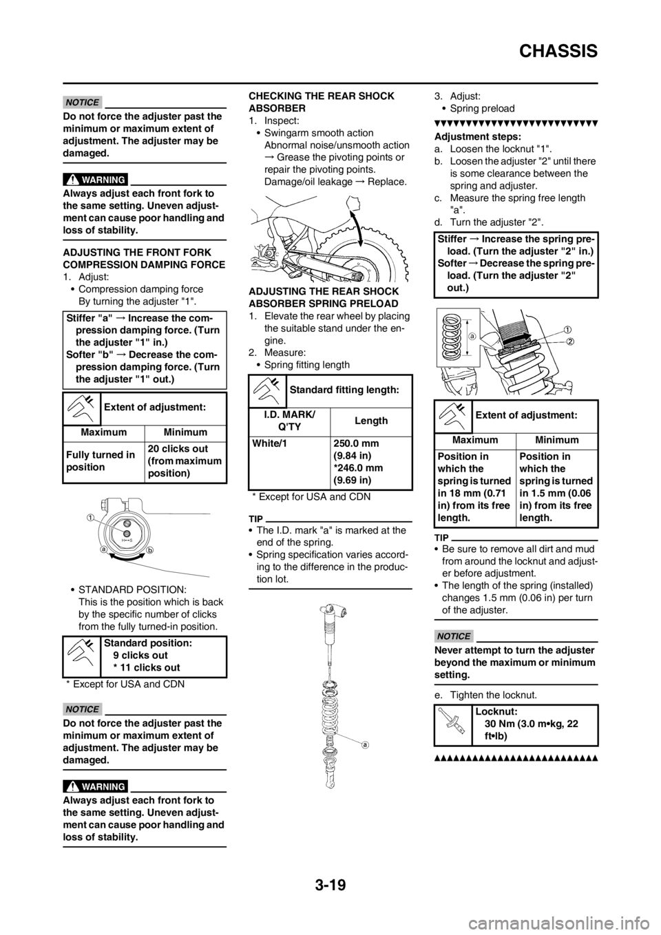
ADJUSTING THE FRONT FORK
COMPRESSION DAMPING FORCE
1. Adjust:
• Compression damping force
By turning the adjuster "1".
• STANDARD POSITION:
This is the position which is back
by the specific number of clicks
from the fully turned-in position.
Do not force the adjuster past the
minimum or maximum extent of
adjustment. The adjuster may be
damaged.
Always adjust each front fork to
the same setting. Uneven adjust-
ment can cause poor handling and
loss of stability.
CHECKING THE REAR SHOCK
ABSORBER
1. Inspect:
• Swingarm smooth action
Abnormal noise/unsmooth action
→Grease the pivoting points or
repair the pivoting points.
Damage/oil leakage→Replace.
ADJUSTING THE REAR SHOCK
ABSORBER SPRING PRELOAD
1. Elevate the rear wheel by placing
the suitable stand under the en-
gine.
2. Measure:
• Spring fitting length
• The I.D. mark "a" is marked at the
end of the spring.
• Spring specification varies accord-
ing to the difference in the produc-
tion lot.
3. Adjust:
• Spring preload
Adjustment steps:
a. Loosen the locknut "1".
b. Loosen the adjuster "2" until there
is some clearance between the
spring and adjuster.
c. Measure the spring free length
"a".
d. Turn the adjuster "2".
• Be sure to remove all dirt and mud
from around the locknut and adjust-
er before adjustment.
• The length of the spring (installed)
changes 1.5 mm (0.06 in) per turn
of the adjuster.
Never attempt to turn the adjuster
beyond the maximum or minimum
setting.
e. Tighten the locknut.
Stiffer "a" →Increase the com-
pression damping force. (Turn
the adjuster "1" in.)
Softer "b" →Decrease the com-
pression damping force. (Turn
the adjuster "1" out.)
Extent of adjustment:
Maximum Minimum
Fully turned in
position20 clicks out
(from maximum
position)
Standard position:
9 clicks out
* 11 clicks out
* Except for USA and CDN
Standard fitting length:
I.D. MARK/
Q'TYLength
White/1 250.0 mm
(9.84 in)
*246.0 mm
(9.69 in)
* Except for USA and CDN
Stiffer →Increase the spring pre-
load. (Turn the adjuster "2" in.)
Softer→Decrease the spring pre-
load. (Turn the adjuster "2"
out.)
Extent of adjustment:
Maximum Minimum
Position in
which the
spring is turned
in 18 mm (0.71
in) from its free
length.Position in
which the
spring is turned
in 1.5 mm (0.06
in) from its free
length.
Locknut:
30 Nm (3.0 m•kg, 22
ft•lb)