fuel pressure YAMAHA YZ450F 2014 User Guide
[x] Cancel search | Manufacturer: YAMAHA, Model Year: 2014, Model line: YZ450F, Model: YAMAHA YZ450F 2014Pages: 360, PDF Size: 11.76 MB
Page 104 of 360
ENGINE
3-16
7. Pour the specified amount of engine oil into
the oil filler cap hole.
8. Install:
• Oil filler cap
9. Check:
• Oil level
Refer to “CHECKING THE ENGINE OIL
LEVEL” on page 3-14.
10.Check:
• Engine oil pressure
▼▼▼▼▼▼▼▼▼▼▼▼▼▼▼▼▼▼▼▼▼▼▼▼▼▼▼▼▼▼▼▼
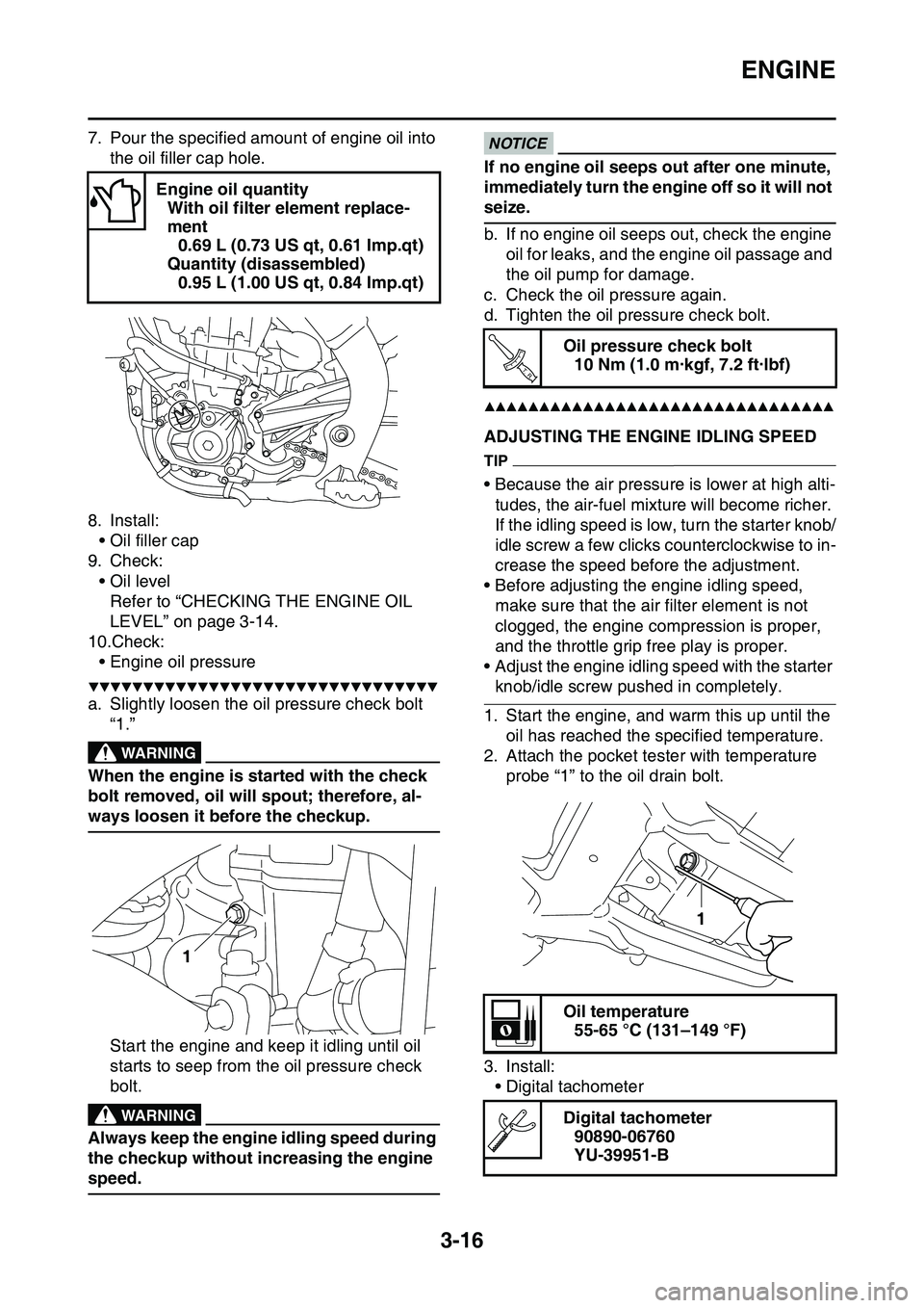
a. Slightly loosen the oil pressure check bolt
“1.”
EWA
WARNING
When the engine is started with the check
bolt removed, oil will spout; therefore, al
-
ways loosen it before the checkup.
Start the engine and keep it idling until oil
starts to seep from the oil pressure check
bolt.
EWA
WARNING
Always keep the engine idling speed during
the checkup without increasing the engine
speed.
ECA
NOTICE
If no engine oil seeps out after one minute,
immediately turn the engine off so it will not
seize.
b. If no engine oil seeps out, check the engine
oil for leaks, and the engine oil passage and
the oil pump for damage.
c. Check the oil pressure again.
d. Tighten the oil pressure check bolt.
▲▲▲▲▲▲▲▲▲▲▲▲▲▲▲▲▲▲▲▲▲▲▲▲▲▲▲▲▲▲▲▲
EAS1SL1087ADJUSTING THE ENGINE IDLING SPEED
TIP
• Because the air pressure is lower at high alti-
tudes, the air-fuel mixture will become richer.
If the idling speed is low, turn the starter knob/
idle screw a few clicks counterclockwise to in
-
crease the speed before the adjustment.
• Before adjusting the engine idling speed,
make sure that the air filter element is not
clogged, the engine compression is proper,
and the throttle grip free play is proper.
• Adjust the engine idling speed with the starter
knob/idle screw pushed in completely.
1. Start the engine, and warm this up until the
oil has reached the specified temperature.
2. Attach the pocket tester with temperature
probe “1” to the oil drain bolt.
3. Install:
• Digital tachometer
Engine oil quantity
With oil filter element replace-
ment
0.69 L (0.73 US qt, 0.61 Imp.qt)
Quantity (disassembled)
0.95 L (1.00 US qt, 0.84 Imp.qt)
1
Oil pressure check bolt
10 Nm (1.0 m·kgf, 7.2 ft·lbf)
Oil temperature
55-65 °C (131–149 °F)
Digital tachometer
90890-06760
YU-39951-B
T R..
1
Page 279 of 360
7
FUEL SYSTEM
FUEL TANK...................................................................................................... 7-1
REMOVING THE FUEL TANK ................................................................... 7-2
REMOVING THE FUEL PUMP .................................................................. 7-2
CHECKING THE FUEL PUMP BODY........................................................ 7-2
INSTALLING THE FUEL PUMP ................................................................. 7-2
INSTALLING THE FUEL TANK.................................................................. 7-3
CHECKING THE FUEL PRESSURE ......................................................... 7-3
CHECKING THE DAMPER ........................................................................ 7-4
CHECKING AND REPLACING THE PROTECTOR .................................. 7-4
THROTTLE BODY............................................................................................ 7-5
CHECKING THE INJECTOR ..................................................................... 7-8
CHECKING THE THROTTLE BODY ......................................................... 7-8
CHECKING THE THROTTLE BODY JOINT .............................................. 7-8
ADJUSTING THE THROTTLE POSITION SENSOR................................. 7-9
Page 281 of 360
FUEL TANK
7-2
EAS1SL1306REMOVING THE FUEL TANK
1. Extract the fuel in the fuel tank through the
fuel tank cap with a pump.
2. Remove:
• Fuel hose couplerEWA23P1001
WARNING
Cover the fuel hose connection with a cloth
when disconnecting it. This is because re
-
sidual pressure in the fuel hose could cause
fuel to spurt out when the hose is removed.
ECA23P1090
NOTICE
Make sure that the fuel hose is disconnect-
ed by hand. Do not forcefully disconnect the
hose with tools.
TIP
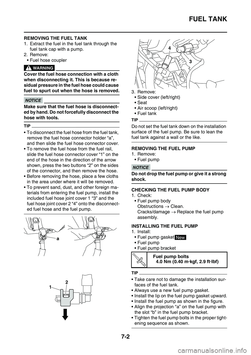
• To disconnect the fuel hose from the fuel tank,
remove the fuel hose connector holder “a”,
and then slide the fuel hose connector cover.
• To remove the fuel hose from the fuel rail,
slide the fuel hose connector cover “1” on the
end of the hose in the direction of the arrow
shown, press the two buttons “2” on the sides
of the connector, and then remove the hose.
• Before removing the hose, place a few cloths
in the area under where it will be removed.
• To prevent sand, dust, and other foreign ma-
terials from entering the fuel pump, install the
included fuel hose joint cover 1 “3” and the
fuel hose joint cover 2 “4” onto the disconnect
-
ed fuel hose and the fuel pump.
3. Remove:
• Side cover (left/right)
• Seat
• Air scoop (left/right)
• Fuel tank
TIP
Do not set the fuel tank down on the installation
surface of the fuel pump. Be sure to lean the
fuel tank against a wall or the like.
EAS1SL1307REMOVING THE FUEL PUMP
1. Remove:
• Fuel pumpECA14720
NOTICE
Do not drop the fuel pump or give it a strong
shock.
EAS1SL1308CHECKING THE FUEL PUMP BODY
1. Check:
• Fuel pump body
Obstructions Clean.
Cracks/damage Replace the fuel pump
assembly.
EAS1SL1309INSTALLING THE FUEL PUMP
1. Install:
• Fuel pump gasket
• Fuel pump
• Fuel pump bracket
TIP
• Take care not to damage the installation sur-
faces of the fuel tank.
• Always use a new fuel pump gasket.
• Install the lip on the fuel pump gasket upward.
• Install the fuel pump as shown in the figure.
• Align the projection “a” on the fuel pump with
the slot “b” in the fuel pump bracket.
• Tighten the fuel pump bolts in the proper tight-
ening sequence as shown.
a
1
2
Fuel pump bolts
4.0 Nm (0.40 m·kgf, 2.9 ft·lbf)
3 4
New
T R..
Page 282 of 360
FUEL TANK
7-3
EAS1SL1310INSTALLING THE FUEL TANK
1. Install:
• Fuel tank
2. Connect:
• Fuel hoseECA33DD069
NOTICE
• Connect the fuel hose securely, and check
that the orientation of the installed fuel
hose holder is correct.
• Take care not to kink or pinch the fuel
hose.
TIP
• Insert the fuel hose into the fuel pipe securely
until you hear a “click.”
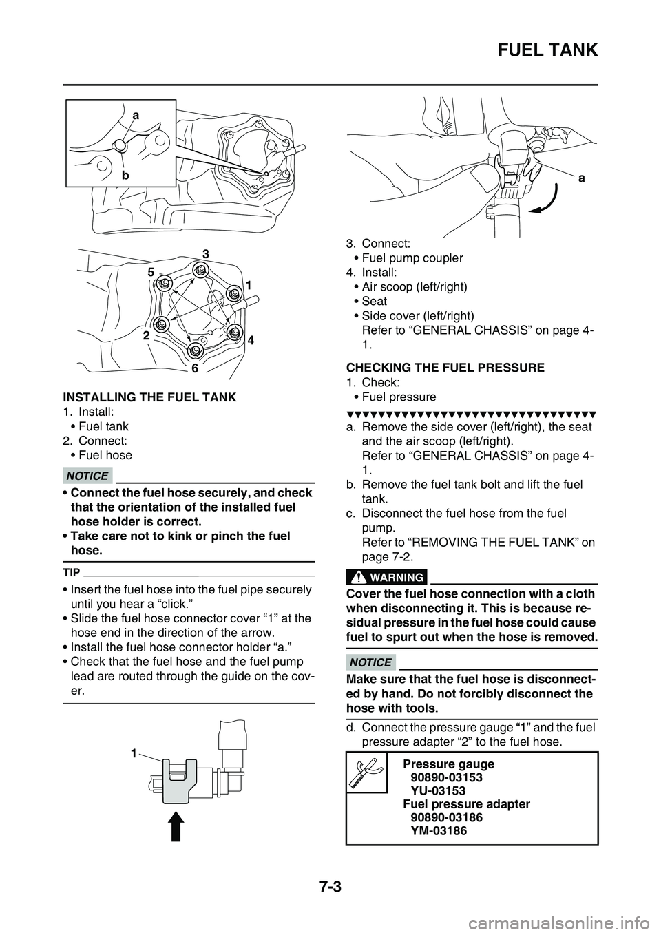
• Slide the fuel hose connector cover “1” at the
hose end in the direction of the arrow.
• Install the fuel hose connector holder “a.”
• Check that the fuel hose and the fuel pump
lead are routed through the guide on the cov
-
er.
3. Connect:
• Fuel pump coupler
4. Install:
• Air scoop (left/right)
• Seat
• Side cover (left/right)
Refer to “GENERAL CHASSIS” on page 4-
1.
EAS1SL1311CHECKING THE FUEL PRESSURE
1. Check:
• Fuel pressure
▼▼▼▼▼▼▼▼▼▼▼▼▼▼▼▼▼▼▼▼▼▼▼▼▼▼▼▼▼▼▼▼
a. Remove the side cover (left/right), the seat
and the air scoop (left/right).
Refer to “GENERAL CHASSIS” on page 4-
1.
b. Remove the fuel tank bolt and lift the fuel
tank.
c. Disconnect the fuel hose from the fuel
pump.
Refer to “REMOVING THE FUEL TANK” on
page 7-2.EWA1DX1008
WARNING
Cover the fuel hose connection with a cloth
when disconnecting it. This is because re
-
sidual pressure in the fuel hose could cause
fuel to spurt out when the hose is removed.
ECA1DX1025
NOTICE
Make sure that the fuel hose is disconnect-
ed by hand. Do not forcibly disconnect the
hose with tools.
d. Connect the pressure gauge “1” and the fuel
pressure adapter “2” to the fuel hose.
a
b
4 1
2
6
53
1Pressure gauge
90890-03153
YU-03153
Fuel pressure adapter
90890-03186
YM-03186
a
Page 283 of 360
FUEL TANK
7-4
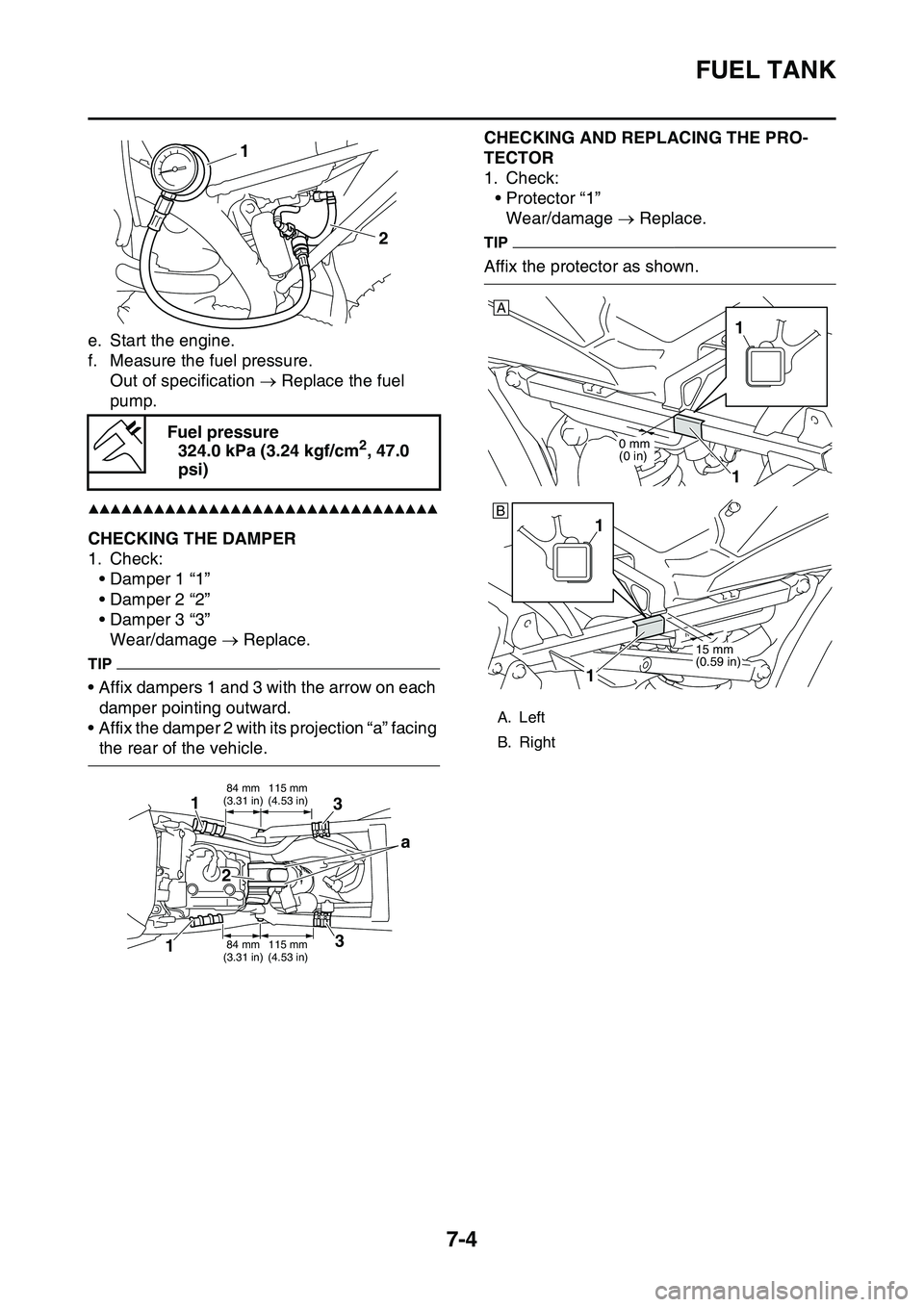
e. Start the engine.
f. Measure the fuel pressure.
Out of specification Replace the fuel
pump.
▲▲▲▲▲▲▲▲▲▲▲▲▲▲▲▲▲▲▲▲▲▲▲▲▲▲▲▲▲▲▲▲
EAS1SL1312CHECKING THE DAMPER
1. Check:
• Damper 1 “1”
• Damper 2 “2”
• Damper 3 “3”
Wear/damage Replace.
TIP
• Affix dampers 1 and 3 with the arrow on each
damper pointing outward.
• Affix the damper 2 with its projection “a” facing
the rear of the vehicle.
EAS1SL1313
CHECKING AND REPLACING THE PRO-
TECTOR
1. Check:
• Protector “1”
Wear/damage Replace.
TIP
Affix the protector as shown.
Fuel pressure
324.0 kPa (3.24 kgf/cm2, 47.0
psi)
1
2
84 mm
(3.31 in)115 mm
(4.53 in)
84 mm
(3.31 in)115 mm
(4.53 in)
3 1
13a
2
A. Left
B. Right
1
1
0 mm
(0 in)
A
B
1
15 mm
(0.59 in)
1
Page 284 of 360
THROTTLE BODY
7-5
EAS1SL1314
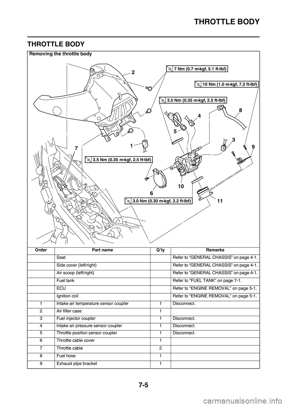
THROTTLE BODY
Removing the throttle body
OrderPart nameQ’tyRemarks
SeatRefer to “GENERAL CHASSIS” on page 4-1.
Side cover (left/right)Refer to “GENERAL CHASSIS” on page 4-1.
Air scoop (left/right)Refer to “GENERAL CHASSIS” on page 4-1.
Fuel tankRefer to “FUEL TANK” on page 7-1.
ECURefer to “ENGINE REMOVAL” on page 5-1.
Ignition coilRefer to “ENGINE REMOVAL” on page 5-1.
1Intake air temperature sensor coupler1Disconnect.
2Air filter case1
3Fuel injector coupler1Disconnect.
4Intake air pressure sensor coupler1Disconnect.
5Throttle position sensor coupler1Disconnect.
6Throttle cable cover1
7Throttle cable2
8Fuel hose1
9Exhaust pipe bracket1
2
1
6
10
11
9
8
3
7
5
4
3.5 Nm (0.35 mkgf, 2.5 ftIbf)T.R.
3.5 Nm (0.35 mkgf, 2.5 ftIbf)T.R.
7 Nm (0.7 mkgf, 5.1 ftIbf)T.R.
3.0 Nm (0.30 mkgf, 2.2 ftIbf)T.R.
10 Nm (1.0 mkgf, 7.2 ftIbf)T.R.
Page 286 of 360
THROTTLE BODY
7-7
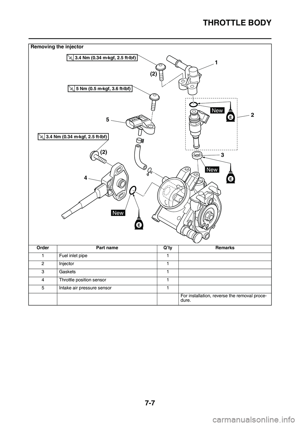
Removing the injector
OrderPart nameQ’tyRemarks
1Fuel inlet pipe1
2Injector1
3Gaskets1
4Throttle position sensor1
5Intake air pressure sensor1
For installation, reverse the removal proce-dure.
1
2 (2)
(2)5
43
T.R.3.4 Nm (0.34 mlbf) kgf, 2.5 ft
T.R.5 Nm (0.5 mlbf) kgf, 3.6 ft
T.R.3.4 Nm (0.34 mlbf) kgf, 2.5 ft
Page 287 of 360
THROTTLE BODY
7-8
EAS1SL1315CHECKING THE INJECTOR
1. Check:
• Injector
Obstruction Replace, and check the fuel
pump and the fuel injection system.
Refer to “FUEL INJECTION SYSTEM” on
page 8-10.
Deposits Replace.
Damage Replace.
2. Check:
• Injector resistance
Refer to “CHECKING THE FUEL INJEC-
TOR” on page 8-47.
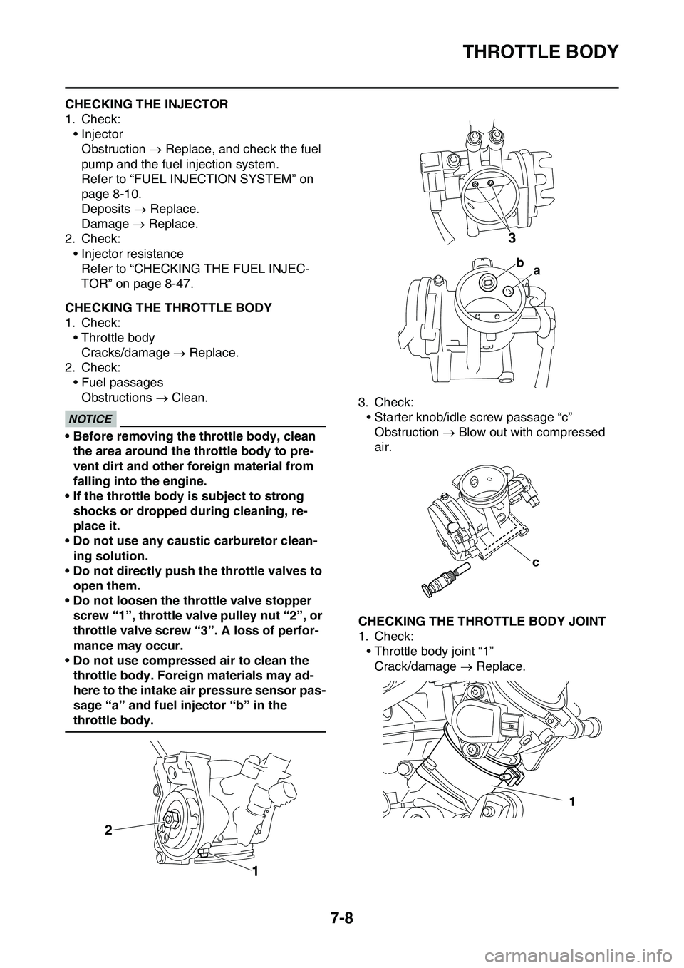
EAS1SL1316CHECKING THE THROTTLE BODY
1. Check:
• Throttle body
Cracks/damage Replace.
2. Check:
• Fuel passages
Obstructions Clean.ECA1DX1027
NOTICE
• Before removing the throttle body, clean
the area around the throttle body to pre
-
vent dirt and other foreign material from
falling into the engine.
• If the throttle body is subject to strong
shocks or dropped during cleaning, re
-
place it.
• Do not use any caustic carburetor clean-
ing solution.
• Do not directly push the throttle valves to
open them.
• Do not loosen the throttle valve stopper
screw “1”, throttle valve pulley nut “2”, or
throttle valve screw “3”. A loss of perfor
-
mance may occur.
• Do not use compressed air to clean the
throttle body. Foreign materials may ad
-
here to the intake air pressure sensor pas-
sage “a” and fuel injector “b” in the
throttle body.
3. Check:
• Starter knob/idle screw passage “c”
Obstruction Blow out with compressed
air.
EAS1SL1317CHECKING THE THROTTLE BODY JOINT
1. Check:
• Throttle body joint “1”
Crack/damage Replace.
EAS1SL1318
1 2
3
ba
c
1
Page 289 of 360
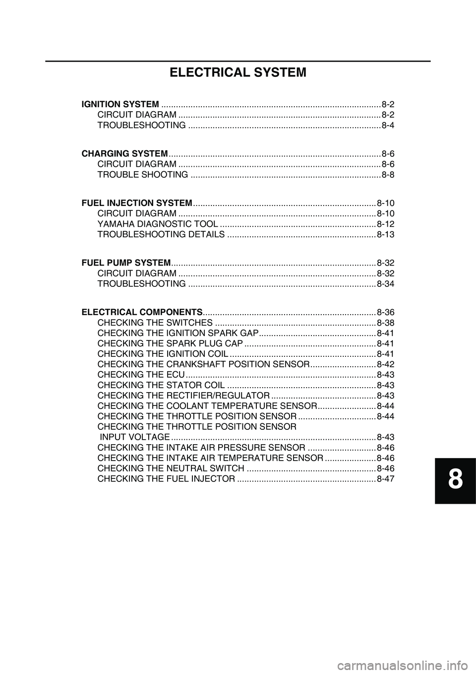
8
ELECTRICAL SYSTEM
IGNITION SYSTEM.......................................................................................... 8-2
CIRCUIT DIAGRAM ................................................................................... 8-2
TROUBLESHOOTING ............................................................................... 8-4
CHARGING SYSTEM....................................................................................... 8-6
CIRCUIT DIAGRAM ................................................................................... 8-6
TROUBLE SHOOTING .............................................................................. 8-8
FUEL INJECTION SYSTEM........................................................................... 8-10
CIRCUIT DIAGRAM ................................................................................. 8-10
YAMAHA DIAGNOSTIC TOOL ................................................................ 8-12
TROUBLESHOOTING DETAILS ............................................................. 8-13
FUEL PUMP SYSTEM.................................................................................... 8-32
CIRCUIT DIAGRAM ................................................................................. 8-32
TROUBLESHOOTING ............................................................................. 8-34
ELECTRICAL COMPONENTS....................................................................... 8-36
CHECKING THE SWITCHES .................................................................. 8-38
CHECKING THE IGNITION SPARK GAP................................................ 8-41
CHECKING THE SPARK PLUG CAP ...................................................... 8-41
CHECKING THE IGNITION COIL ............................................................ 8-41
CHECKING THE CRANKSHAFT POSITION SENSOR........................... 8-42
CHECKING THE ECU .............................................................................. 8-43
CHECKING THE STATOR COIL ............................................................. 8-43
CHECKING THE RECTIFIER/REGULATOR ........................................... 8-43
CHECKING THE COOLANT TEMPERATURE SENSOR........................ 8-44
CHECKING THE THROTTLE POSITION SENSOR ................................ 8-44
CHECKING THE THROTTLE POSITION SENSOR
INPUT VOLTAGE .................................................................................... 8-43
CHECKING THE INTAKE AIR PRESSURE SENSOR ............................ 8-46
CHECKING THE INTAKE AIR TEMPERATURE SENSOR ..................... 8-46
CHECKING THE NEUTRAL SWITCH ..................................................... 8-46
CHECKING THE FUEL INJECTOR ......................................................... 8-47
Page 301 of 360
FUEL INJECTION SYSTEM
8-11
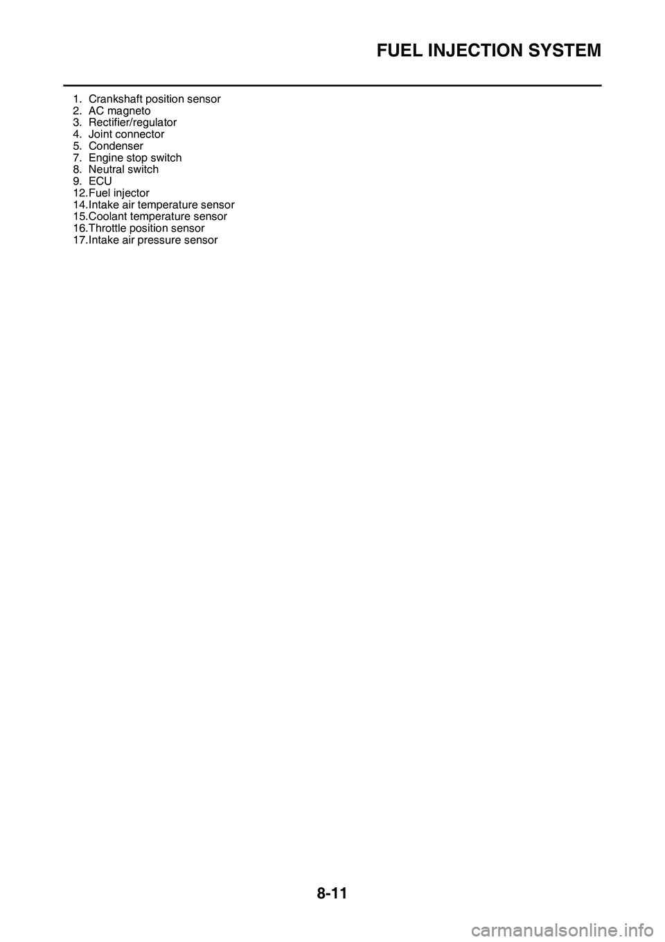
EAS1SL1327
1. Crankshaft position sensor
2. AC magneto
3. Rectifier/regulator
4. Joint connector
5. Condenser
7. Engine stop switch
8. Neutral switch
9. ECU
12.Fuel injector
14.Intake air temperature sensor
15.Coolant temperature sensor
16.Throttle position sensor
17.Intake air pressure sensor