oil filter YAMAHA YZ450F 2014 User Guide
[x] Cancel search | Manufacturer: YAMAHA, Model Year: 2014, Model line: YZ450F, Model: YAMAHA YZ450F 2014Pages: 360, PDF Size: 11.76 MB
Page 90 of 360
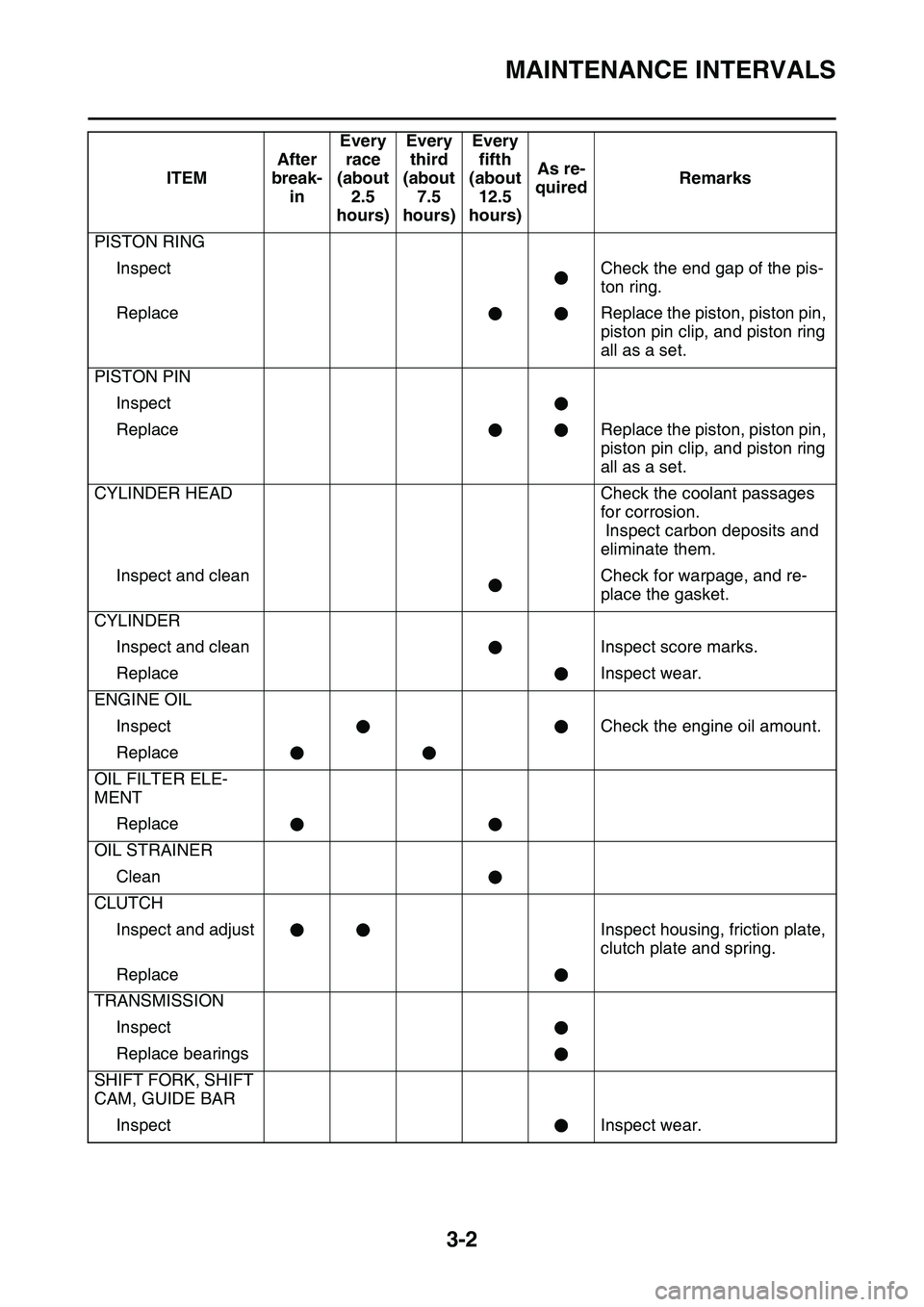
MAINTENANCE INTERVALS
3-2
PISTON RING
InspectCheck the end gap of the pis-
ton ring.
ReplaceReplace the piston, piston pin,
piston pin clip, and piston ring
all as a set.
PISTON PIN
Inspect
ReplaceReplace the piston, piston pin,
piston pin clip, and piston ring
all as a set.
CYLINDER HEADCheck the coolant passages
for corrosion.
Inspect carbon deposits and
eliminate them.
Inspect and cleanCheck for warpage, and re-
place the gasket.
CYLINDER
Inspect and cleanInspect score marks.
ReplaceInspect wear.
ENGINE OIL
InspectCheck the engine oil amount.
Replace
OIL FILTER ELE-
MENT
Replace
OIL STRAINER
Clean
CLUTCH
Inspect and adjustInspect housing, friction plate,
clutch plate and spring.
Replace
TRANSMISSION
Inspect
Replace bearings
SHIFT FORK, SHIFT
CAM, GUIDE BAR
InspectInspect wear.
ITEMAfter
break-
inEvery
race
(about
2.5
hours)Every
third
(about
7.5
hours)Every
fifth
(about
12.5
hours)As re-
quiredRemarks
Page 91 of 360
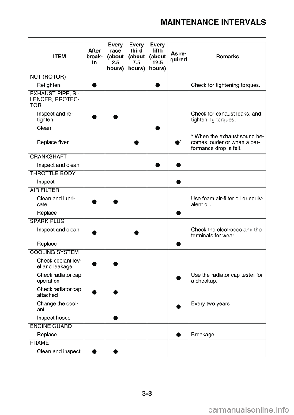
MAINTENANCE INTERVALS
3-3
NUT (ROTOR)
RetightenCheck for tightening torques.
EXHAUST PIPE, SI-
LENCER, PROTEC-
TOR
Inspect and re-
tighten
Check for exhaust leaks, and
tightening torques.
Clean
Replace fiver*
* When the exhaust sound be-
comes louder or when a per-
formance drop is felt.
CRANKSHAFT
Inspect and clean
THROTTLE BODY
Inspect
AIR FILTER
Clean and lubri-
cate
Use foam air-filter oil or equiv-
alent oil.
Replace
SPARK PLUG
Inspect and cleanCheck the electrodes and the
terminals for wear.
Replace
COOLING SYSTEM
Check coolant lev-
el and leakage
Check radiator cap
operationUse the radiator cap tester for
a checkup.
Check radiator cap
attached
Change the cool-
ant
Every two years
Inspect hoses
ENGINE GUARD
ReplaceBreakage
FRAME
Clean and inspect
ITEMAfter
break-
inEvery
race
(about
2.5
hours)Every
third
(about
7.5
hours)Every
fifth
(about
12.5
hours)As re-
quiredRemarks
Page 100 of 360
ENGINE
3-12
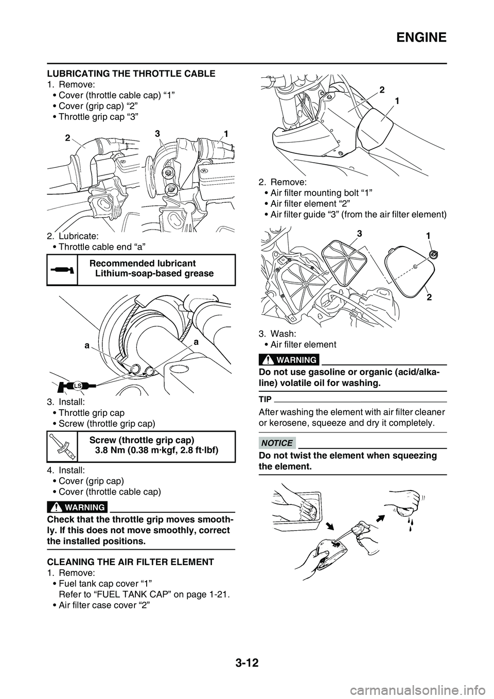
LUBRICATING THE THROTTLE CABLE
1. Remove:• Cover (throttle cable cap) “1”
• Cover (grip cap) “2”
• Throttle grip cap “3”
2. Lubricate: • Throttle cable end “a”
3. Install: • Throttle grip cap
• Screw (throttle grip cap)
4. Install: • Cover (grip cap)
• Cover (throttle cable cap)
EWA
WARNING
Check that the throttle grip moves smooth-
ly. If this does not move smoothly, correct
the installed positions.
EAS1SL1080CLEANING THE AIR FILTER ELEMENT
1. Remove:• Fuel tank cap cover “1”Refer to “FUEL TANK CAP” on page 1-21.
• Air filter case cover “2” 2. Remove:
• Air filter mounting bolt “1”
• Air filter element “2”
• Air filter guide “3” (from the air filter element)
3. Wash: • Air filter element
EWA
WARNING
Do not use gasoline or organic (acid/alka-
line) volatile oil for washing.
TIP
After washing the element with air filter cleaner
or kerosene, squeeze and dry it completely.
ECA33DD016
NOTICE
Do not twist the element when squeezing
the element.
Recommended lubricant
Lithium-soap-based grease
Screw (throttle grip cap) 3.8 Nm (0.38 m·kgf, 2.8 ft·lbf)
T R..
1
2
13
2
Page 101 of 360
ENGINE
3-13
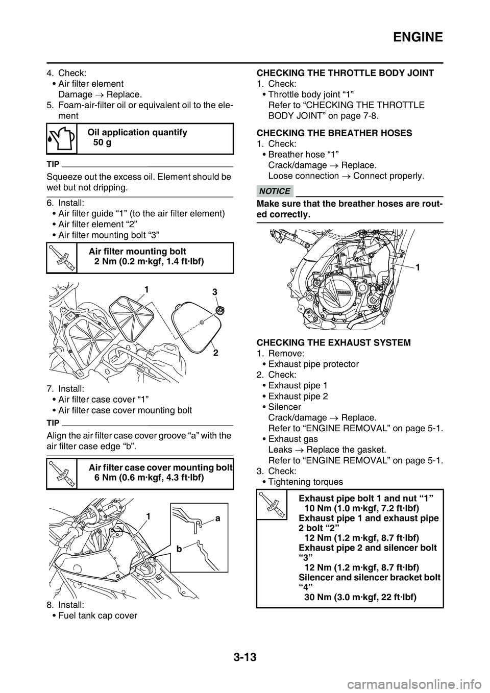
4. Check:• Air filter elementDamage Replace.
5. Foam-air-filter oil or equivalent oil to the ele- ment
TIP
Squeeze out the excess oil. Element should be
wet but not dripping.
6. Install:• Air filter guide “1” (to the air filter element)
• Air filter element “2”
• Air filter mounting bolt “3”
7. Install: • Air filter case cover “1”
• Air filter case cover mounting bolt
TIP
Align the air filter case cover groove “a” with the
air filter case edge “b”.
8. Install:• Fuel tank cap cover
EAS1SL1081
CHECKING THE THROTTLE BODY JOINT
1. Check:• Throttle body joint “1”
Refer to “CHECKING THE THROTTLE
BODY JOINT” on page 7-8.
EAS1SL1082CHECKING THE BREATHER HOSES
1. Check:• Breather hose “1”Crack/damage Replace.
Loose connection Connect properly.
ECA14920
NOTICE
Make sure that the breather hoses are rout-
ed correctly.
EAS1SL1083CHECKING THE EXHAUST SYSTEM
1. Remove:
• Exhaust pipe protector
2. Check:
• Exhaust pipe 1
• Exhaust pipe 2
• SilencerCrack/damage Replace.
Refer to “ENGINE REMOVAL” on page 5-1.
• Exhaust gas
Leaks Replace the gasket.
Refer to “ENGINE REMOVAL” on page 5-1.
3. Check:
• Tightening torques
Oil application quantify
50 g
Air filter mounting bolt 2 Nm (0.2 m·kgf, 1.4 ft·lbf)
Air filter case cover mounting bolt 6 Nm (0.6 m·kgf, 4.3 ft·lbf)
T R..
31
2
T R..
a
b
1
Exhaust pipe bolt 1 and nut “1”
10 Nm (1.0 m·kgf, 7.2 ft·lbf)
Exhaust pipe 1 and exhaust pipe
2 bolt “2” 12 Nm (1.2 m·kgf, 8.7 ft·lbf)
Exhaust pipe 2 and silencer bolt
“3” 12 Nm (1.2 m·kgf, 8.7 ft·lbf)
Silencer and silencer bracket bolt
“4” 30 Nm (3.0 m·kgf, 22 ft·lbf)
1
T R..
Page 103 of 360
ENGINE
3-15
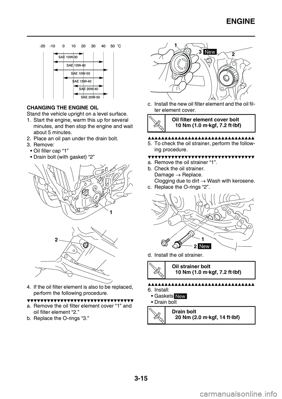
EAS1SL1086CHANGING THE ENGINE OIL
Stand the vehicle upright on a level surface.
1. Start the engine, warm this up for several
minutes, and then stop the engine and wait
about 5 minutes.
2. Place an oil pan under the drain bolt.
3. Remove:
• Oil filler cap “1”
• Drain bolt (with gasket) “2”
4. If the oil filter element is also to be replaced,
perform the following procedure.
▼▼▼▼▼▼▼▼▼▼▼▼▼▼▼▼▼▼▼▼▼▼▼▼▼▼▼▼▼▼▼▼
a. Remove the oil filter element cover “1” and
oil filter element “2.”
b. Replace the O-rings “3.”
c. Install the new oil filter element and the oil fil-
ter element cover.
▲▲▲▲▲▲▲▲▲▲▲▲▲▲▲▲▲▲▲▲▲▲▲▲▲▲▲▲▲▲▲▲
5. To check the oil strainer, perform the follow-
ing procedure.
▼▼▼▼▼▼▼▼▼▼▼▼▼▼▼▼▼▼▼▼▼▼▼▼▼▼▼▼▼▼▼▼
a. Remove the oil strainer “1”.
b. Check the oil strainer.
Damage Replace.
Clogging due to dirt Wash with kerosene.
c. Replace the O-rings “2”.
d. Install the oil strainer.
▲▲▲▲▲▲▲▲▲▲▲▲▲▲▲▲▲▲▲▲▲▲▲▲▲▲▲▲▲▲▲▲
6. Install:
•Gaskets
• Drain bolt
1
2
Oil filter element cover bolt
10 Nm (1.0 m·kgf, 7.2 ft·lbf)
Oil strainer bolt
10 Nm (1.0 m·kgf, 7.2 ft·lbf)
Drain bolt
20 Nm (2.0 m·kgf, 14 ft·lbf)
1
3
2
New
T R..
1
2New
T R..
New
T R..
Page 104 of 360
ENGINE
3-16
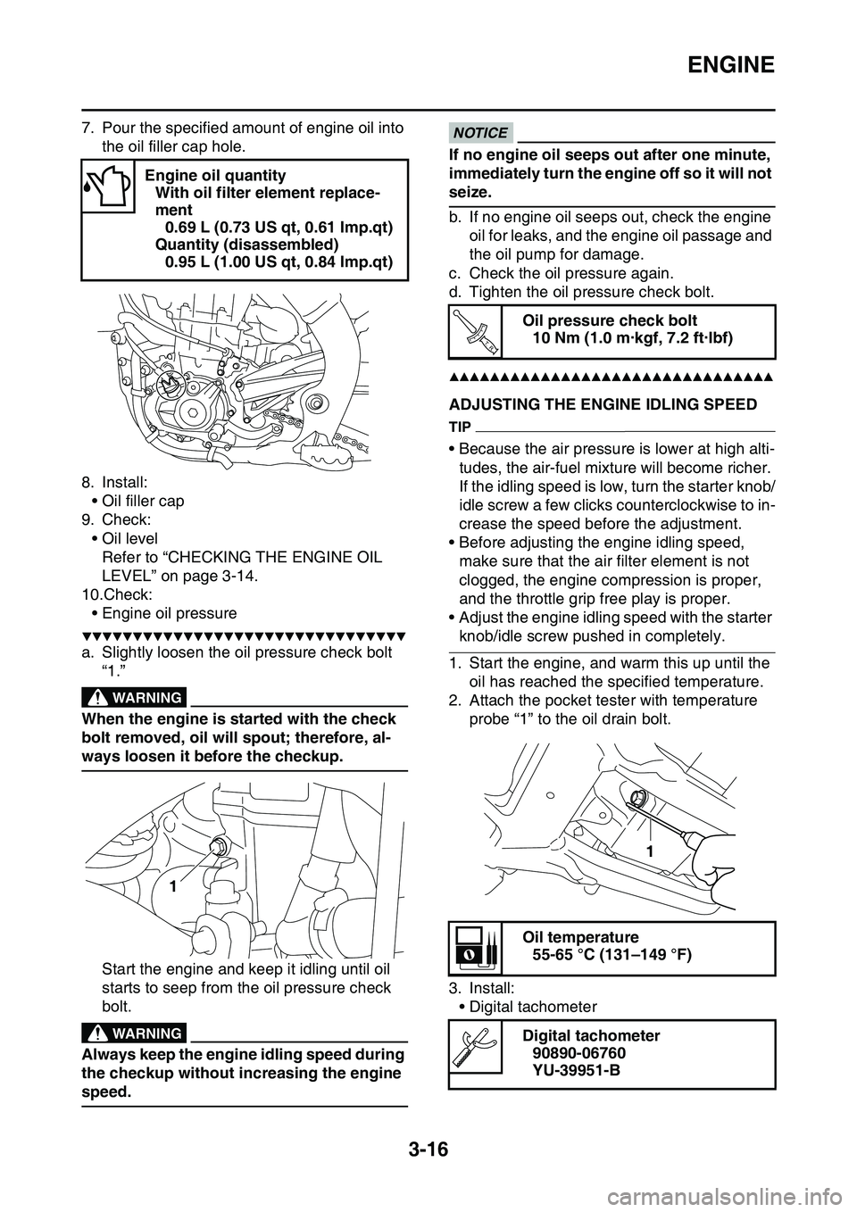
7. Pour the specified amount of engine oil into
the oil filler cap hole.
8. Install:
• Oil filler cap
9. Check:
• Oil level
Refer to “CHECKING THE ENGINE OIL
LEVEL” on page 3-14.
10.Check:
• Engine oil pressure
▼▼▼▼▼▼▼▼▼▼▼▼▼▼▼▼▼▼▼▼▼▼▼▼▼▼▼▼▼▼▼▼
a. Slightly loosen the oil pressure check bolt
“1.”
EWA
WARNING
When the engine is started with the check
bolt removed, oil will spout; therefore, al
-
ways loosen it before the checkup.
Start the engine and keep it idling until oil
starts to seep from the oil pressure check
bolt.
EWA
WARNING
Always keep the engine idling speed during
the checkup without increasing the engine
speed.
ECA
NOTICE
If no engine oil seeps out after one minute,
immediately turn the engine off so it will not
seize.
b. If no engine oil seeps out, check the engine
oil for leaks, and the engine oil passage and
the oil pump for damage.
c. Check the oil pressure again.
d. Tighten the oil pressure check bolt.
▲▲▲▲▲▲▲▲▲▲▲▲▲▲▲▲▲▲▲▲▲▲▲▲▲▲▲▲▲▲▲▲
EAS1SL1087ADJUSTING THE ENGINE IDLING SPEED
TIP
• Because the air pressure is lower at high alti-
tudes, the air-fuel mixture will become richer.
If the idling speed is low, turn the starter knob/
idle screw a few clicks counterclockwise to in
-
crease the speed before the adjustment.
• Before adjusting the engine idling speed,
make sure that the air filter element is not
clogged, the engine compression is proper,
and the throttle grip free play is proper.
• Adjust the engine idling speed with the starter
knob/idle screw pushed in completely.
1. Start the engine, and warm this up until the
oil has reached the specified temperature.
2. Attach the pocket tester with temperature
probe “1” to the oil drain bolt.
3. Install:
• Digital tachometer
Engine oil quantity
With oil filter element replace-
ment
0.69 L (0.73 US qt, 0.61 Imp.qt)
Quantity (disassembled)
0.95 L (1.00 US qt, 0.84 Imp.qt)
1
Oil pressure check bolt
10 Nm (1.0 m·kgf, 7.2 ft·lbf)
Oil temperature
55-65 °C (131–149 °F)
Digital tachometer
90890-06760
YU-39951-B
T R..
1
Page 198 of 360
ENGINE REMOVAL
5-3
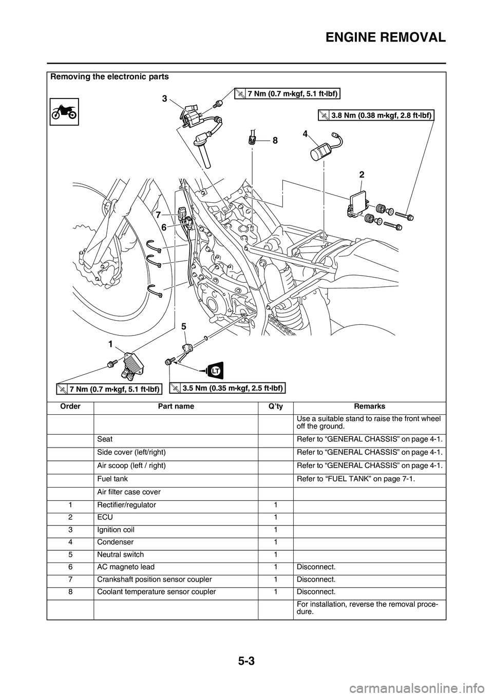
Removing the electronic parts
OrderPart nameQ’tyRemarks
Use a suitable stand to raise the front wheel
off the ground.
SeatRefer to “GENERAL CHASSIS” on page 4-1.
Side cover (left/right)Refer to “GENERAL CHASSIS” on page 4-1.
Air scoop (left / right)Refer to “GENERAL CHASSIS” on page 4-1.
Fuel tankRefer to “FUEL TANK” on page 7-1.
Air filter case cover
1Rectifier/regulator1
2ECU1
3Ignition coil1
4Condenser1
5Neutral switch1
6AC magneto lead1Disconnect.
7Crankshaft position sensor coupler1Disconnect.
8Coolant temperature sensor coupler1Disconnect.
For installation, reverse the removal proce-dure.
T.R.
T.R.
T.R.T.R.
8 3
7
6
154
2
LT
Page 234 of 360
CLUTCH
5-39
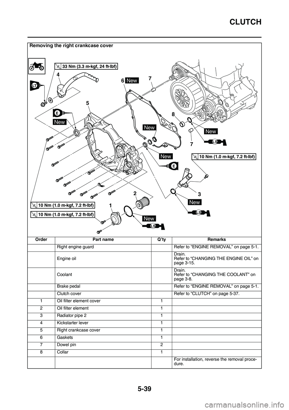
Removing the right crankcase cover
OrderPart nameQ’tyRemarks
Right engine guardRefer to “ENGINE REMOVAL” on page 5-1.
Engine oilDrain.Refer to “CHANGING THE ENGINE OIL” on page 3-15.
CoolantDrain.Refer to “CHANGING THE COOLANT” on page 3-8.
Brake pedalRefer to “ENGINE REMOVAL” on page 5-1.
Clutch coverRefer to “CLUTCH” on page 5-37.
1Oil filter element cover1
2Oil filter element1
3Radiator pipe 21
4Kickstarter lever1
5Right crankcase cover1
6Gaskets1
7Dowel pin2
8Collar1
For installation, reverse the removal proce-dure.
T.R.
E
E
LS
New
New
67
2
5
4
1
7 8
New
3
LS
New
New
LS
NewNew
LT
Page 284 of 360
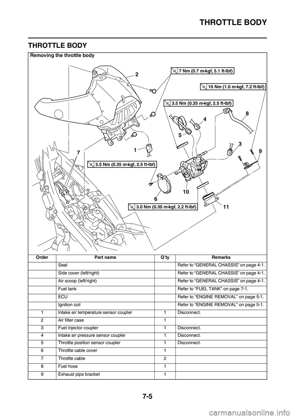
THROTTLE BODY
7-5
EAS1SL1314
THROTTLE BODY
Removing the throttle body
OrderPart nameQ’tyRemarks
SeatRefer to “GENERAL CHASSIS” on page 4-1.
Side cover (left/right)Refer to “GENERAL CHASSIS” on page 4-1.
Air scoop (left/right)Refer to “GENERAL CHASSIS” on page 4-1.
Fuel tankRefer to “FUEL TANK” on page 7-1.
ECURefer to “ENGINE REMOVAL” on page 5-1.
Ignition coilRefer to “ENGINE REMOVAL” on page 5-1.
1Intake air temperature sensor coupler1Disconnect.
2Air filter case1
3Fuel injector coupler1Disconnect.
4Intake air pressure sensor coupler1Disconnect.
5Throttle position sensor coupler1Disconnect.
6Throttle cable cover1
7Throttle cable2
8Fuel hose1
9Exhaust pipe bracket1
2
1
6
10
11
9
8
3
7
5
4
3.5 Nm (0.35 mkgf, 2.5 ftIbf)T.R.
3.5 Nm (0.35 mkgf, 2.5 ftIbf)T.R.
7 Nm (0.7 mkgf, 5.1 ftIbf)T.R.
3.0 Nm (0.30 mkgf, 2.2 ftIbf)T.R.
10 Nm (1.0 mkgf, 7.2 ftIbf)T.R.
Page 294 of 360
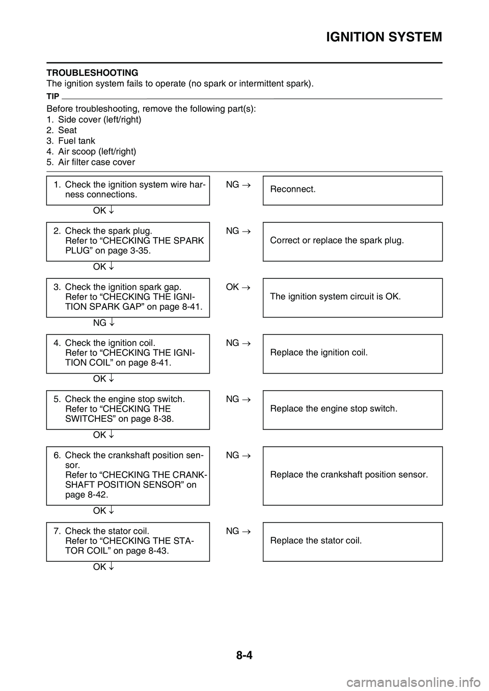
IGNITION SYSTEM
8-4
TROUBLESHOOTING
The ignition system fails to operate (no spark or intermittent spark).
TIP
Before troubleshooting, remove the following part(s):
1. Side cover (left/right)
2. Seat
3. Fuel tank
4. Air scoop (left/right)
5. Air filter case cover
1. Check the ignition system wire har-
ness connections.
NG Reconnect.
OK
2. Check the spark plug.
Refer to “CHECKING THE SPARK
PLUG” on page 3-35.
NG
Correct or replace the spark plug.
OK
3. Check the ignition spark gap.
Refer to “CHECKING THE IGNI-
TION SPARK GAP” on page 8-41.
OK
The ignition system circuit is OK.
NG
4. Check the ignition coil.
Refer to “CHECKING THE IGNI-
TION COIL” on page 8-41.
NG
Replace the ignition coil.
OK
5. Check the engine stop switch.
Refer to “CHECKING THE
SWITCHES” on page 8-38.
NG
Replace the engine stop switch.
OK
6. Check the crankshaft position sen-
sor.
Refer to “CHECKING THE CRANK-
SHAFT POSITION SENSOR” on
page 8-42.
NG
Replace the crankshaft position sensor.
OK
7. Check the stator coil.
Refer to “CHECKING THE STA-
TOR COIL” on page 8-43.
NG
Replace the stator coil.
OK