oil pressure YAMAHA YZ450F 2014 User Guide
[x] Cancel search | Manufacturer: YAMAHA, Model Year: 2014, Model line: YZ450F, Model: YAMAHA YZ450F 2014Pages: 360, PDF Size: 11.76 MB
Page 75 of 360
LUBRICATION SYSTEM CHART AND DIAGRAMS
2-32
1. Camshaft
2. Oil pressure check bolt3. Oil filter element
4. Oil pump
Page 87 of 360
3
PERIODIC CHECKS AND ADJUSTMENTS
MAINTENANCE INTERVALS.......................................................................... 3-1
MAINTENANCE INTERVALS .................................................................... 3-1
PRE-OPERATION INSPECTION AND MAINTENANCE................................. 3-7
GENERAL INSPECTION AND MAINTENANCE........................................ 3-7
ENGINE............................................................................................................ 3-8
CHECKING THE COOLANT LEVEL .......................................................... 3-8
CHECKING THE COOLING SYSTEM ....................................................... 3-8
CHANGING THE COOLANT...................................................................... 3-8
CHECKING THE RADIATOR CAP ............................................................ 3-9
CHECKING THE RADIATOR CAP OPENING PRESSURE ...................... 3-9
CHECKING THE COOLANT CIRCULATORY SYSTEM FOR LEAKS .... 3-10
ADJUSTING THE CLUTCH LEVER POSITION ...................................... 3-10
ADJUSTING THE CLUTCH LEVER FREE PLAY .................................... 3-10
ADJUSTING THE THROTTLE GRIP FREE PLAY .................................. 3-11
LUBRICATING THE THROTTLE CABLE ................................................ 3-12
CLEANING THE AIR FILTER ELEMENT................................................. 3-12
CHECKING THE THROTTLE BODY JOINT ............................................ 3-13
CHECKING THE BREATHER HOSES .................................................... 3-13
CHECKING THE EXHAUST SYSTEM..................................................... 3-13
CHECKING THE FUEL LINE ................................................................... 3-14
CHECKING THE ENGINE OIL LEVEL..................................................... 3-14
CHANGING THE ENGINE OIL ................................................................ 3-15
ADJUSTING THE ENGINE IDLING SPEED ............................................ 3-16
ADJUSTING THE VALVE CLEARANCE ................................................. 3-17
CHASSIS........................................................................................................ 3-21
BLEEDING THE BRAKE SYSTEM .......................................................... 3-21
CHECKING THE BRAKE HOSE .............................................................. 3-22
ADJUSTING THE FRONT BRAKE .......................................................... 3-22
ADJUSTING THE REAR BRAKE ............................................................. 3-23
CHECKING THE FRONT BRAKE PADS ................................................. 3-23
CHECKING THE REAR BRAKE PADS ................................................... 3-25
CHECKING THE REAR BRAKE PAD INSULATOR ................................ 3-26
CHECKING THE BRAKE FLUID LEVEL.................................................. 3-26
ADJUSTING THE DRIVE CHAIN SLACK ................................................ 3-27
CHECKING THE FRONT FORK LEGS ................................................... 3-28
CHECKING THE FRONT FORK PROTECTOR GUIDE .......................... 3-28
CLEANING THE FRONT FORK OIL SEAL AND DUST SEAL ................ 3-28
AIR BLEEDING FROM FRONT FORK .................................................... 3-28
ADJUSTING THE FRONT FORK LEGS .................................................. 3-29
CHECKING THE SWINGARM OPERATION ........................................... 3-30
CHECKING THE REAR SUSPENSION ................................................... 3-30
ADJUSTING THE REAR SHOCK ABSORBER ASSEMBLY ................... 3-30
CHECKING THE TIRES ........................................................................... 3-32
CHECKING AND TIGHTENING THE SPOKES ....................................... 3-32
CHECKING THE WHEELS ...................................................................... 3-33
Page 95 of 360
PRE-OPERATION INSPECTION AND MAINTENANCE
3-7
EAS1SL1067
PRE-OPERATION INSPECTION AND MAINTENANCE
Before riding for break-in operation, practice or a race, make sure the machine is in good operating
condition.
Before using this machine, check the following points.
EAS1SL1068GENERAL INSPECTION AND MAINTENANCE
TIP
Perform usual maintenance enough so that, in the race course, a confirmation of that and simple set-
ting adjustments may only be left, in order to get enough time to use effectively.
ITEMinspectPage
CoolantCheck that coolant is filled up to the radiator cap.
Check the cooling system for leakage.3-8 – 10
FuelCheck that a fresh gasoline is filled in the fuel tank.
Check the fuel line for leakage.1-22
Engine oilCheck that the oil level is correct. Check the crank-
case and oil line for leakage.3-14 – 16
Gear shifter and clutchCheck that gears can be shifted correctly in order and
that the clutch operates smoothly.3-10 – 11
Throttle grip/Housing
Check that the throttle grip operation and free play
are correctly adjusted. Lubricate the throttle grip and
housing, if necessary.
3-11 – 12
BrakesCheck the play of front brake and effect of front and
rear brake.3-21 – 27
Drive chainCheck drive chain slack and alignment. Check that
the drive chain is lubricated properly.3-27
4-64 – 65
WheelsCheck for excessive wear and tire pressure. Check
for loose spokes and have no excessive play.3-32 – 33
SteeringCheck that the handlebar can be turned smoothly and
have no excessive play.3-33 – 34
Front forks and rear
shock absorberCheck that they operate smoothly and there is no oil
leakage.3-28 – 32
Cables (wires)
Check that the clutch and throttle cables move
smoothly. Check that they are not caught when the
handlebars are turned or when the front forks travel
up and down.
—
Exhaust pipeCheck that the exhaust pipe is tightly mounted and
has no cracks.3-13 – 14
Rear wheel sprocketCheck that the rear wheel sprocket tightening bolt is
not loose.4-8 – 9
LubricationCheck for smooth operation. Lubricate if necessary. 3-12 , 3-34
Bolts and nutsCheck the chassis and engine for loose bolts and
nuts.1-25 – 26
Lead connectorsCheck that the AC magneto, ECU and ignition coil are
connected tightly.1-12 – 14
Settings
Is the machine set suitably for the condition of the rac-
ing course and weather or by taking into account the
results of test runs before racing? Are inspection and
maintenance completely done?10-1 – 8
Page 104 of 360
ENGINE
3-16
7. Pour the specified amount of engine oil into
the oil filler cap hole.
8. Install:
• Oil filler cap
9. Check:
• Oil level
Refer to “CHECKING THE ENGINE OIL
LEVEL” on page 3-14.
10.Check:
• Engine oil pressure
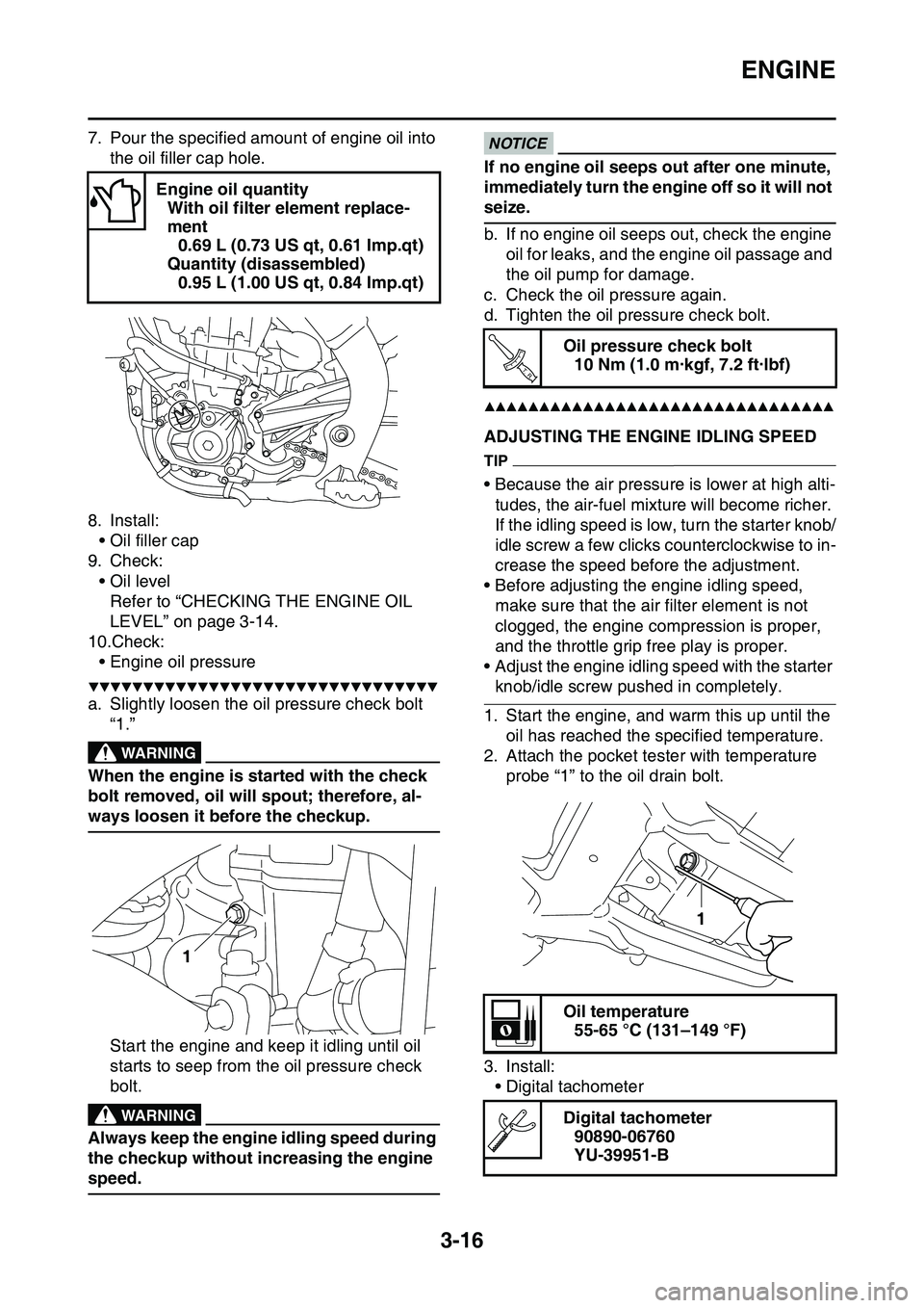
▼▼▼▼▼▼▼▼▼▼▼▼▼▼▼▼▼▼▼▼▼▼▼▼▼▼▼▼▼▼▼▼
a. Slightly loosen the oil pressure check bolt
“1.”
EWA
WARNING
When the engine is started with the check
bolt removed, oil will spout; therefore, al
-
ways loosen it before the checkup.
Start the engine and keep it idling until oil
starts to seep from the oil pressure check
bolt.
EWA
WARNING
Always keep the engine idling speed during
the checkup without increasing the engine
speed.
ECA
NOTICE
If no engine oil seeps out after one minute,
immediately turn the engine off so it will not
seize.
b. If no engine oil seeps out, check the engine
oil for leaks, and the engine oil passage and
the oil pump for damage.
c. Check the oil pressure again.
d. Tighten the oil pressure check bolt.
▲▲▲▲▲▲▲▲▲▲▲▲▲▲▲▲▲▲▲▲▲▲▲▲▲▲▲▲▲▲▲▲
EAS1SL1087ADJUSTING THE ENGINE IDLING SPEED
TIP
• Because the air pressure is lower at high alti-
tudes, the air-fuel mixture will become richer.
If the idling speed is low, turn the starter knob/
idle screw a few clicks counterclockwise to in
-
crease the speed before the adjustment.
• Before adjusting the engine idling speed,
make sure that the air filter element is not
clogged, the engine compression is proper,
and the throttle grip free play is proper.
• Adjust the engine idling speed with the starter
knob/idle screw pushed in completely.
1. Start the engine, and warm this up until the
oil has reached the specified temperature.
2. Attach the pocket tester with temperature
probe “1” to the oil drain bolt.
3. Install:
• Digital tachometer
Engine oil quantity
With oil filter element replace-
ment
0.69 L (0.73 US qt, 0.61 Imp.qt)
Quantity (disassembled)
0.95 L (1.00 US qt, 0.84 Imp.qt)
1
Oil pressure check bolt
10 Nm (1.0 m·kgf, 7.2 ft·lbf)
Oil temperature
55-65 °C (131–149 °F)
Digital tachometer
90890-06760
YU-39951-B
T R..
1
Page 116 of 360
CHASSIS
3-28
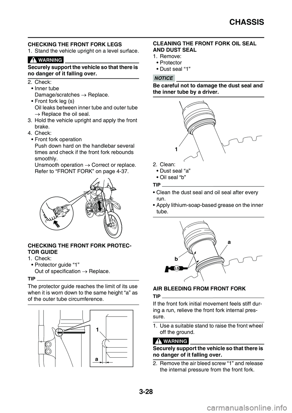
EAS1SL1099CHECKING THE FRONT FORK LEGS
1. Stand the vehicle upright on a level surface.EWA13120
WARNING
Securely support the vehicle so that there is
no danger of it falling over.
2. Check:
• Inner tube
Damage/scratches Replace.
• Front fork leg (s)
Oil leaks between inner tube and outer tube
Replace the oil seal.
3. Hold the vehicle upright and apply the front
brake.
4. Check:
• Front fork operation
Push down hard on the handlebar several
times and check if the front fork rebounds
smoothly.
Unsmooth operation Correct or replace.
Refer to “FRONT FORK” on page 4-37.
EAS1SL1100CHECKING THE FRONT FORK PROTEC-
TOR GUIDE
1. Check:
• Protector guide “1”
Out of specification Replace.
TIP
The protector guide reaches the limit of its use
when it is worn down to the same height “a” as
of the outer tube circumference.
EAS1SL1101
CLEANING THE FRONT FORK OIL SEAL
AND DUST SEAL
1. Remove:
•Protector
• Dust seal “1”ECA?
NOTICE
Be careful not to damage the dust seal and
the inner tube by a driver.
2. Clean:
• Dust seal “a”
• Oil seal “b”
TIP
• Clean the dust seal and oil seal after every
run.
• Apply lithium-soap-based grease on the inner
tube.
EAS1SL1102AIR BLEEDING FROM FRONT FORK
TIP
If the front fork initial movement feels stiff dur-
ing a run, relieve the front fork internal pres-
sure.
1. Use a suitable stand to raise the front wheel
off the ground.
EWA@
WARNING
Securely support the vehicle so that there is
no danger of it falling over.
2. Remove the air bleed screw “1” and release
the internal pressure from the front fork.
1
a
1
LS
a
b
Page 168 of 360
FRONT FORK
4-42
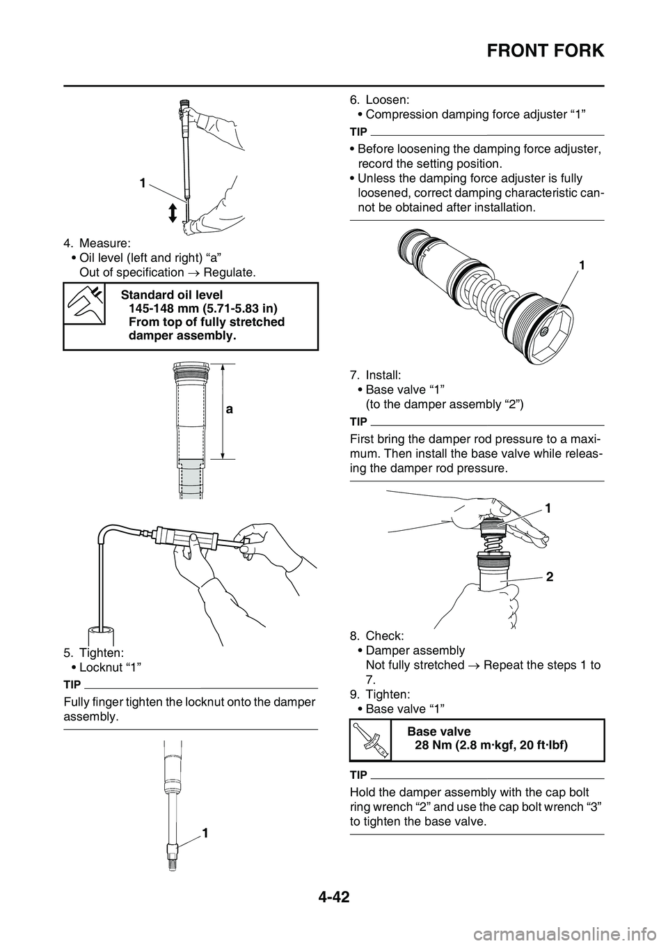
4. Measure:
• Oil level (left and right) “a”
Out of specification Regulate.
5. Tighten:
• Locknut “1”
TIP
Fully finger tighten the locknut onto the damper
assembly.
6. Loosen:
• Compression damping force adjuster “1”
TIP
• Before loosening the damping force adjuster,
record the setting position.
• Unless the damping force adjuster is fully
loosened, correct damping characteristic can
-
not be obtained after installation.
7. Install:
• Base valve “1”
(to the damper assembly “2”)
TIP
First bring the damper rod pressure to a maxi-
mum. Then install the base valve while releas-
ing the damper rod pressure.
8. Check:
• Damper assembly
Not fully stretched Repeat the steps 1 to
7.
9. Tighten:
• Base valve “1”
TIP
Hold the damper assembly with the cap bolt
ring wrench “2” and use the cap bolt wrench “3”
to tighten the base valve.
Standard oil level
145-148 mm (5.71-5.83 in)
From top of fully stretched
damper assembly.
1
a
Base valve
28 Nm (2.8 m·kgf, 20 ft·lbf)
1
1
2
T R..
Page 194 of 360
CLUTCH......................................................................................................... 5-37
REMOVING THE CLUTCH ...................................................................... 5-40
CHECKING THE FRICTION PLATES...................................................... 5-40
CHECKING THE CLUTCH PLATES ........................................................ 5-40
CHECKING THE CLUTCH SPRINGS...................................................... 5-40
CHECKING THE CLUTCH HOUSING ..................................................... 5-41
CHECKING THE CLUTCH BOSS ............................................................ 5-41
CHECKING THE PRESSURE PLATE ..................................................... 5-41
CHECKING THE PUSH LEVER SHAFT .................................................. 5-41
CHECKING THE CLUTCH PUSH RODS ................................................ 5-41
CHECKING THE PRIMARY DRIVE GEAR .............................................. 5-41
CHECKING THE PRIMARY DRIVEN GEAR ........................................... 5-42
INSTALLING THE OIL SEAL................................................................... 5-42
INSTALLING THE RIGHT CRANKCASE COVER ................................... 5-42
INSTALLING THE CLUTCH ..................................................................... 5-42
INSTALLING THE KICKSTARTER LEVER ............................................. 5-45
KICKSTATER................................................................................................. 5-46
REMOVING THE KICK SHAFT ASSEMBLY ........................................... 5-47
CHECKING THE KICK SHAFT AND RATCHET WHEEL ........................ 5-47
CHECKING THE KICK GEAR, KICK IDLE GEAR,
AND RATCHET WHEEL ......................................................................... 5-47
INSTALLING THE KICK SHAFT ASSEMBLY .......................................... 5-47
INSTALLING THE KICK IDLE GEAR ....................................................... 5-48
SHIFT SHAFT................................................................................................. 5-49
REMOVING THE SHIFT GUIDE AND SHIFT LEVER ASSEMBLY ......... 5-51
REMOVING THE SEGMENT ................................................................... 5-51
CHECKING THE SHIFT SHAFT .............................................................. 5-51
CHECKING THE SHIFT GUIDE AND SHIFT LEVER ASSEMBLY ......... 5-51
CHECKING THE STOPPER LEVER ....................................................... 5-51
INSTALLING THE STOPPER LEVER ..................................................... 5-52
INSTALLING THE SEGMENT.................................................................. 5-52
INSTALLING THE SHIFT GUIDE AND SHIFT LEVER ASSEMBLY ....... 5-52
INSTALLING THE SHIFT SHAFT ............................................................ 5-53
INSTALLING THE SHIFT PEDAL ............................................................ 5-53
OIL PUMP AND BALANCER GEAR............................................................. 5-54
REMOVING THE BALANCER ................................................................. 5-56
CHECKING THE PRIMARY DRIVE GEAR, BALANCER SHAFT
DRIVE GEAR, AND BALANCER WEIGHT GEAR ................................. 5-56
CHECKING THE BALANCER .................................................................. 5-56
CHECKING THE OIL PUMP .................................................................... 5-56
ASSEMBLING THE OIL PUMP ................................................................ 5-57
INSTALLING THE OIL PUMP AND BALANCER GEAR .......................... 5-57
Page 232 of 360
CLUTCH
5-37
EAS1SL1232
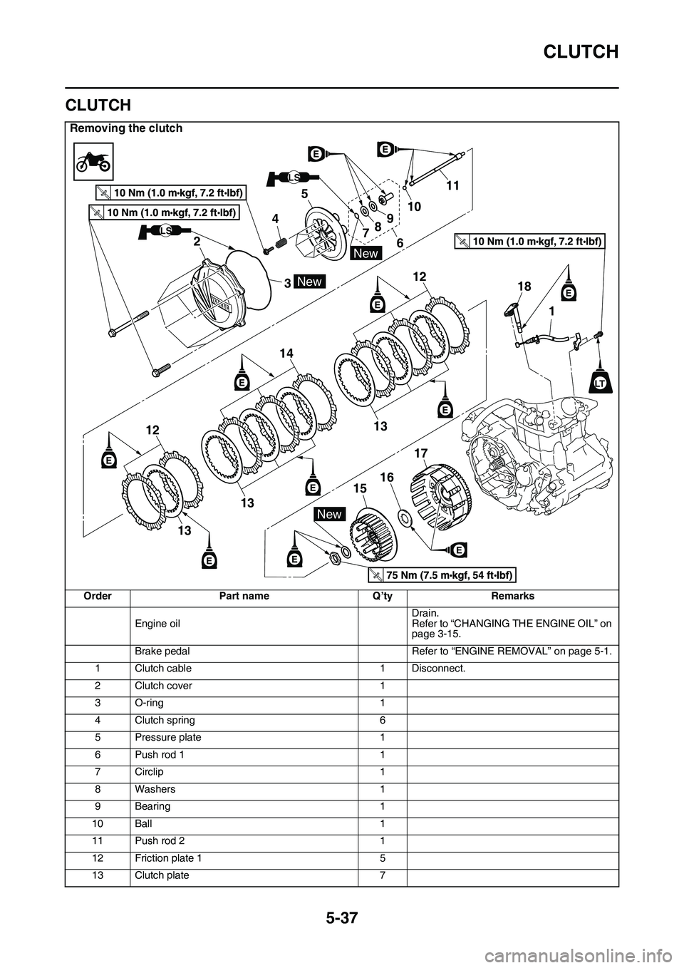
CLUTCH
Removing the clutch
OrderPart nameQ’tyRemarks
Engine oilDrain.Refer to “CHANGING THE ENGINE OIL” on page 3-15.
Brake pedalRefer to “ENGINE REMOVAL” on page 5-1.
1Clutch cable1Disconnect.
2Clutch cover1
3O-ring1
4Clutch spring6
5Pressure plate1
6Push rod 11
7Circlip1
8Washers1
9Bearing1
10Ball1
11Push rod 21
12Friction plate 15
13Clutch plate7
LS
LS
New
New
New
2
3 45
789
61011
13
12
12
18
1
14
13
13
17
16
15
T.R.
T.R.
T.R.
T.R.
LT
Page 239 of 360

CLUTCH
5-44
6. Install:
• Push rod 2 “1”
•Ball “2”
• Push rod 1 “3”
TIP
Apply the engine oil on the push rod 1, 2 and
ball.
7. Install:
• Pressure plate “1”
8. Install:
• Clutch spring
• Clutch spring bolt
TIP
Tighten the bolts in stages and in a crisscross
pattern.
9. Install:
• O-ring “1”
TIP
Apply the lithium-soap-based grease to the O-
ring.
10.Install:
• Clutch cover “1”
• Clutch cover bolt
TIP
Tighten the bolts in stages and in a crisscross
pattern.
EAS1SL1247
Clutch spring bolt
10 Nm (1.0 m·kgf, 7.2 ft·lbf)T R..
Clutch cover bolt
10 Nm (1.0 m·kgf, 7.2 ft·lbf)
New
T R..
1
Page 284 of 360
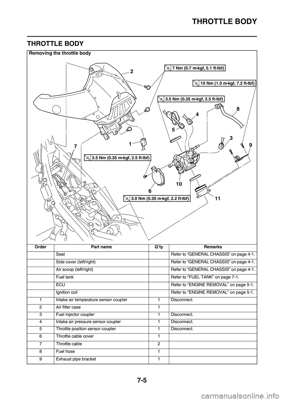
THROTTLE BODY
7-5
EAS1SL1314
THROTTLE BODY
Removing the throttle body
OrderPart nameQ’tyRemarks
SeatRefer to “GENERAL CHASSIS” on page 4-1.
Side cover (left/right)Refer to “GENERAL CHASSIS” on page 4-1.
Air scoop (left/right)Refer to “GENERAL CHASSIS” on page 4-1.
Fuel tankRefer to “FUEL TANK” on page 7-1.
ECURefer to “ENGINE REMOVAL” on page 5-1.
Ignition coilRefer to “ENGINE REMOVAL” on page 5-1.
1Intake air temperature sensor coupler1Disconnect.
2Air filter case1
3Fuel injector coupler1Disconnect.
4Intake air pressure sensor coupler1Disconnect.
5Throttle position sensor coupler1Disconnect.
6Throttle cable cover1
7Throttle cable2
8Fuel hose1
9Exhaust pipe bracket1
2
1
6
10
11
9
8
3
7
5
4
3.5 Nm (0.35 mkgf, 2.5 ftIbf)T.R.
3.5 Nm (0.35 mkgf, 2.5 ftIbf)T.R.
7 Nm (0.7 mkgf, 5.1 ftIbf)T.R.
3.0 Nm (0.30 mkgf, 2.2 ftIbf)T.R.
10 Nm (1.0 mkgf, 7.2 ftIbf)T.R.