engine coolant YAMAHA YZ450F 2014 Owner's Manual
[x] Cancel search | Manufacturer: YAMAHA, Model Year: 2014, Model line: YZ450F, Model: YAMAHA YZ450F 2014Pages: 360, PDF Size: 11.76 MB
Page 276 of 360
WATER PUMP
6-5
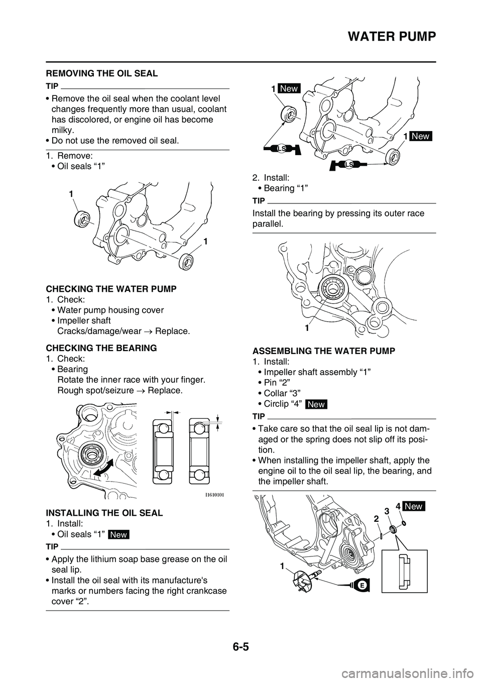
EAS1SL1299REMOVING THE OIL SEAL
TIP
• Remove the oil seal when the coolant level
changes frequently more than usual, coolant
has discolored, or engine oil has become
milky.
• Do not use the removed oil seal.
1. Remove:
• Oil seals “1”
EAS1SL1300CHECKING THE WATER PUMP
1. Check:
• Water pump housing cover
• Impeller shaft
Cracks/damage/wear Replace.
EAS1SL1301CHECKING THE BEARING
1. Check:
• Bearing
Rotate the inner race with your finger.
Rough spot/seizure Replace.
EAS1SL1302INSTALLING THE OIL SEAL
1. Install:
• Oil seals “1”
TIP
• Apply the lithium soap base grease on the oil
seal lip.
• Install the oil seal with its manufacture's
marks or numbers facing the right crankcase
cover “2”.
2. Install:
• Bearing “1”
TIP
Install the bearing by pressing its outer race
parallel.
EAS1SL1303ASSEMBLING THE WATER PUMP
1. Install:
• Impeller shaft assembly “1”
•Pin “2”
• Collar “3”
• Circlip “4”
TIP
• Take care so that the oil seal lip is not dam-
aged or the spring does not slip off its posi-
tion.
• When installing the impeller shaft, apply the
engine oil to the oil seal lip, the bearing, and
the impeller shaft.
1 1
New
1 1New
New
LS
LS
New
4
1
23New
E
Page 301 of 360
FUEL INJECTION SYSTEM
8-11
EAS1SL1327
1. Crankshaft position sensor
2. AC magneto
3. Rectifier/regulator
4. Joint connector
5. Condenser
7. Engine stop switch
8. Neutral switch
9. ECU
12.Fuel injector
14.Intake air temperature sensor
15.Coolant temperature sensor
16.Throttle position sensor
17.Intake air pressure sensor
Page 310 of 360
FUEL INJECTION SYSTEM
8-20
TIP
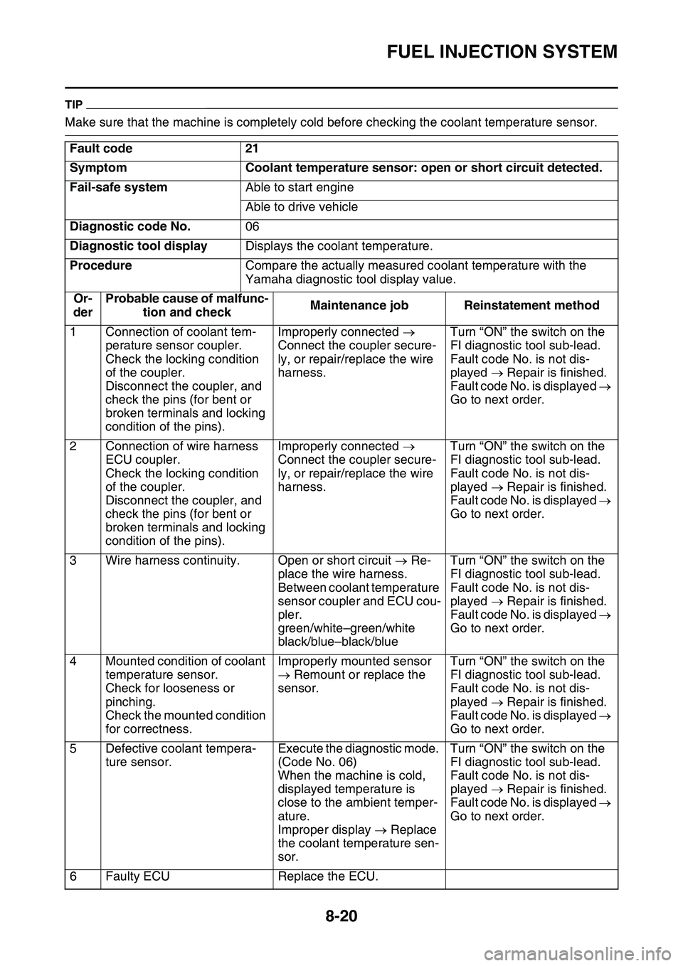
Make sure that the machine is completely cold before checking the coolant temperature sensor.
Fault code21
SymptomCoolant temperature sensor: open or short circuit detected.
Fail-safe systemAble to start engine
Able to drive vehicle
Diagnostic code No.06
Diagnostic tool displayDisplays the coolant temperature.
ProcedureCompare the actually measured coolant temperature with the
Yamaha diagnostic tool display value.
Or-
der
Probable cause of malfunc-
tion and checkMaintenance jobReinstatement method
1Connection of coolant tem-
perature sensor coupler.
Check the locking condition
of the coupler.
Disconnect the coupler, and
check the pins (for bent or
broken terminals and locking
condition of the pins).
Improperly connected
Connect the coupler secure
-
ly, or repair/replace the wire
harness.
Turn “ON” the switch on the
FI diagnostic tool sub-lead.
Fault code No. is not dis-
played Repair is finished.
Fault code No. is displayed
Go to next order.
2Connection of wire harness
ECU coupler.
Check the locking condition
of the coupler.
Disconnect the coupler, and
check the pins (for bent or
broken terminals and locking
condition of the pins).
Improperly connected
Connect the coupler secure
-
ly, or repair/replace the wire
harness.
Turn “ON” the switch on the
FI diagnostic tool sub-lead.
Fault code No. is not dis-
played Repair is finished.
Fault code No. is displayed
Go to next order.
3Wire harness continuity.Open or short circuit Re-
place the wire harness.
Between coolant temperature
sensor coupler and ECU cou
-
pler.
green/white–green/white
black/blue–black/blue
Turn “ON” the switch on the
FI diagnostic tool sub-lead.
Fault code No. is not dis-
played Repair is finished.
Fault code No. is displayed
Go to next order.
4Mounted condition of coolant
temperature sensor.
Check for looseness or
pinching.
Check the mounted condition
for correctness.
Improperly mounted sensor
Remount or replace the
sensor.Turn “ON” the switch on the
FI diagnostic tool sub-lead.
Fault code No. is not dis-
played Repair is finished.
Fault code No. is displayed
Go to next order.
5Defective coolant tempera-
ture sensor.
Execute the diagnostic mode.
(Code No. 06)
When the machine is cold,
displayed temperature is
close to the ambient temper
-
ature.
Improper display Replace
the coolant temperature sen
-
sor.
Turn “ON” the switch on the
FI diagnostic tool sub-lead.
Fault code No. is not dis-
played Repair is finished.
Fault code No. is displayed
Go to next order.
6Faulty ECUReplace the ECU.
Page 341 of 360
TROUBLE SHOOTING
9-2
3. Ignition system
• Faulty ECU
• Faulty crankshaft position sensor
• Broken generator rotor woodruff key
EAS1SL1353POOR MEDIUM-AND-HIGH-SPEED PER-
FORMANCE
Refer to “STARTING FAILURES” on page 9-1.
Engine
1. Air filter
• Clogged air filter element
Fuel system
1. Fuel pump
• Faulty fuel pump
2. Throttle body
• Defective throttle body
3. ECU
• Faulty ECU
EAS1SL1354FAULTY GEAR SHIFTING
Shifting is difficult
Refer to “CLUTCH” on page 5-37.
EAS1SL1355SHIFT PEDAL DOES NOT MOVE
Shift shaft
• Bent shift shaft
Shift drum and shift forks
• Foreign object in a shift drum groove
• Seized shift fork
• Bent shift fork guide bar
Transmission
• Seized transmission gear
• Foreign object between transmission gears
• Improperly assembled transmission
EAS1SL1356JUMPS OUT OF GEAR
Shift shaft
• Incorrect shift pedal position
• Improperly returned stopper lever
Shift forks
• Worn shift fork
Shift drum
• Incorrect axial play
• Worn shift drum groove
Transmission
• Worn gear dog
EAS1SL1357FAULTY CLUTCH
Clutch slips
1. Clutch
• Improperly assembled clutch
• Loose or fatigued clutch spring
• Worn friction plate
• Worn clutch plate
2. Engine oil
• Incorrect oil level
• Incorrect oil viscosity (low)
• Deteriorated oil
Clutch drags
1. Clutch
• Unevenly tensioned clutch springs
• Warped pressure plate
• Bent clutch plate
• Swollen friction plate
• Bent clutch push rod
• Damaged clutch boss
• Burnt primary driven gear bushing
2. Engine oil
• Incorrect oil level
• Incorrect oil viscosity (high)
• Deteriorated oil
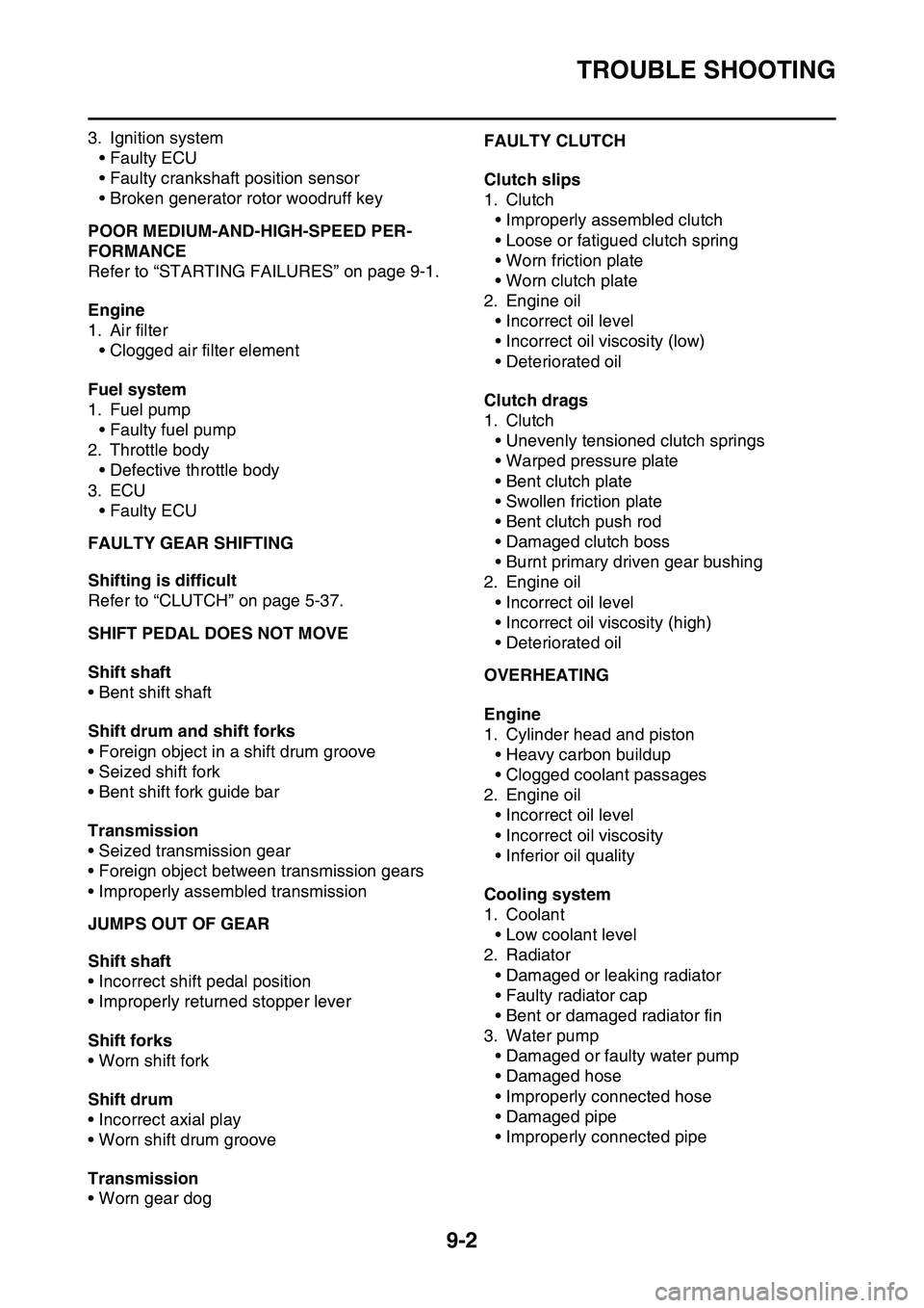
EAS1SL1358OVERHEATING
Engine
1. Cylinder head and piston
• Heavy carbon buildup
• Clogged coolant passages
2. Engine oil
• Incorrect oil level
• Incorrect oil viscosity
• Inferior oil quality
Cooling system
1. Coolant
• Low coolant level
2. Radiator
• Damaged or leaking radiator
• Faulty radiator cap
• Bent or damaged radiator fin
3. Water pump
• Damaged or faulty water pump
• Damaged hose
• Improperly connected hose
• Damaged pipe
• Improperly connected pipe
Page 356 of 360
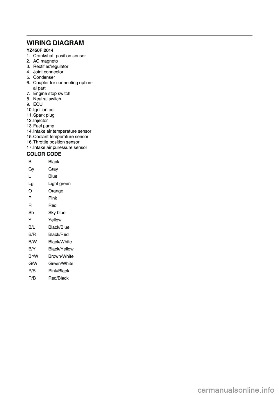
EAS1SL1380
WIRING DIAGRAM
YZ450F 2014
1. Crankshaft position sensor
2. AC magneto
3. Rectifier/regulator
4. Joint connector
5. Condenser
6. Coupler for connecting option-
al part
7. Engine stop switch
8. Neutral switch
9. ECU
10. Ignition coil
11. Spark plug
12. Injector
13. Fuel pump
14. Intake air temperature sensor
15. Coolant temperature sensor
16. Throttle position sensor
17. Intake air puressure sensorEAS1SL1381COLOR CODE
BBlack
GyGray
LBlue
LgLight green
OOrange
PPink
RRed
SbSky blue
YYellow
B/LBlack/Blue
B/RBlack/Red
B/WBlack/White
B/YBlack/Yellow
Br/WBrown/White
G/WGreen/White
P/BPink/Black
R/BRed/Black