length YAMAHA YZ450F 2014 Owners Manual
[x] Cancel search | Manufacturer: YAMAHA, Model Year: 2014, Model line: YZ450F, Model: YAMAHA YZ450F 2014Pages: 360, PDF Size: 11.76 MB
Page 7 of 360
EAS1SL1005
SAFETY INFORMATION
THIS MACHINE IS DESIGNED STRICTLY FOR COMPETITION USE, ONLY ON A CLOSED
COURSE. It is illegal for this machine to be operated on any public street, road, or highway. Off-road
use on public lands may also be illegal. Please check local regulations before riding.
• THIS MACHINE IS TO BE OPERATED BY AN EXPERIENCED RIDER ONLY.
Do not attempt to operate this machine at maximum power until you are totally familiar with its char-
acteristics.
• THIS MACHINE IS DESIGNED TO BE RIDDEN BY THE OPERATOR ONLY.
Do not carry passengers on this machine.
• ALWAYS WEAR PROTECTIVE APPAREL.
When operating this machine, always wear an approved helmet with goggles or a face shield. Also
wear heavy boots, gloves, and protective clothing. Always wear proper fitting clothing that will not
be caught in any of the moving parts or controls of the machine.
• ALWAYS MAINTAIN YOUR MACHINE IN PROPER WORKING ORDER.
For safety and reliability, the machine must be properly maintained. Always perform the pre-oper-
ation checks indicated in this manual.
Correcting a mechanical problem before you ride may prevent an accident.
• GASOLINE IS HIGHLY FLAMMABLE.
Always turn off the engine while refueling. Take care to not spill any gasoline on the engine or ex-
haust system. Never refuel in the vicinity of an open flame, or while smoking.
• GASOLINE CAN CAUSE INJURY.
If you should swallow some gasoline, inhale excess gasoline vapors, or allow any gasoline to get
into your eyes, contact a doctor immediately. If any gasoline spills onto your skin or clothing, imme
-
diately wash skin areas with soap and water, and change your clothes.
• ONLY OPERATE THE MACHINE IN AN AREA WITH ADEQUATE VENTILATION.
Never start the engine or let it run for any length of time in an enclosed area. Exhaust fumes are
poisonous. These fumes contain carbon monoxide, which by itself is odorless and colorless. Car
-
bon monoxide is a dangerous gas which can cause unconsciousness or can be lethal.
• PARK THE MACHINE CAREFULLY; TURN OFF THE ENGINE.
Always turn off the engine if you are going to leave the machine. Do not park the machine on a slope
or soft ground as it may fall over.
• THE ENGINE, EXHAUST PIPE, MUFFLER, AND OIL TANK WILL BE VERY HOT AFTER THE EN-
GINE HAS BEEN RUN.
Be careful not to touch them or to allow any clothing item to contact them during inspection or repair.
• PROPERLY SECURE THE MACHINE BEFORE TRANSPORTING IT.
For safety, drain the gasoline from the fuel tank before transporting the vehicle.
Page 21 of 360
FEATURES
1-7
FI SYSTEM
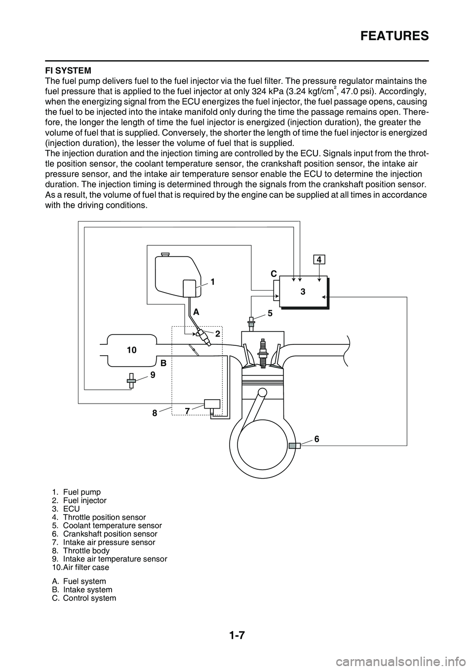
The fuel pump delivers fuel to the fuel injector via the fuel filter. The pressure regulator maintains the
fuel pressure that is applied to the fuel injector at only 324 kPa (3.24 kgf/cm², 47.0 psi). Accordingly,
when the energizing signal from the ECU energizes the fuel injector, the fuel passage opens, causing
the fuel to be injected into the intake manifold only during the time the passage remains open. There
-
fore, the longer the length of time the fuel injector is energized (injection duration), the greater the
volume of fuel that is supplied. Conversely, the shorter the length of time the fuel injector is energized
(injection duration), the lesser the volume of fuel that is supplied.
The injection duration and the injection timing are controlled by the ECU. Signals input from the throt-
tle position sensor, the coolant temperature sensor, the crankshaft position sensor, the intake air
pressure sensor, and the intake air temperature sensor enable the ECU to determine the injection
duration. The injection timing is determined through the signals from the crankshaft position sensor.
As a result, the volume of fuel that is required by the engine can be supplied at all times in accordance
with the driving conditions.
1. Fuel pump
2. Fuel injector
3. ECU
4. Throttle position sensor
5. Coolant temperature sensor
6. Crankshaft position sensor
7. Intake air pressure sensor
8. Throttle body
9. Intake air temperature sensor
10.Air filter case
A. Fuel system
B. Intake system
C. Control system
1
234
5
6 7
8 9 10A
BC
Page 36 of 360
STARTING AND BREAK-IN
1-22
EAS1SL1041
STARTING AND BREAK-IN
EAS1SL1042FUEL
Always use the recommended fuel as stated
below. Also, be sure to use new gasoline the
day of a race.
JCA
NOTICE
Use only unleaded gasoline. The use of
leaded gasoline will cause severe damage
to the engine internal parts such as valves,
piston rings, and exhaust system, etc.
TIP
Your Yamaha engine has been designed to use
premium unleaded gasoline with a pump oc
-
tane number [(R+M)/2] of 91 or higher, or a re-
search octane number of 95 or higher. If
knocking (or pinging) occurs, use a gasoline of
a different brand.
JWA
WARNING
• For refueling, be sure to stop the engine
and use enough care not to spill any fuel.
Also be sure to avoid refueling close to a
fire.
• Refuel after the engine, exhaust pipe, etc.
have cooled off.
Gasohol (For USA and Canada)
There are two types of gasohol: gasohol con-
taining ethanol and that containing methanol.
Gasohol containing ethanol can be used if the
ethanol content does not exceed 10%. Gasohol
containing methanol is not recommended by
Yamaha because it can cause damage to the
fuel system or vehicle performance problems.
EAS1SL1043STARTING A COLD ENGINE
1. Press the shift pedal to neutral.
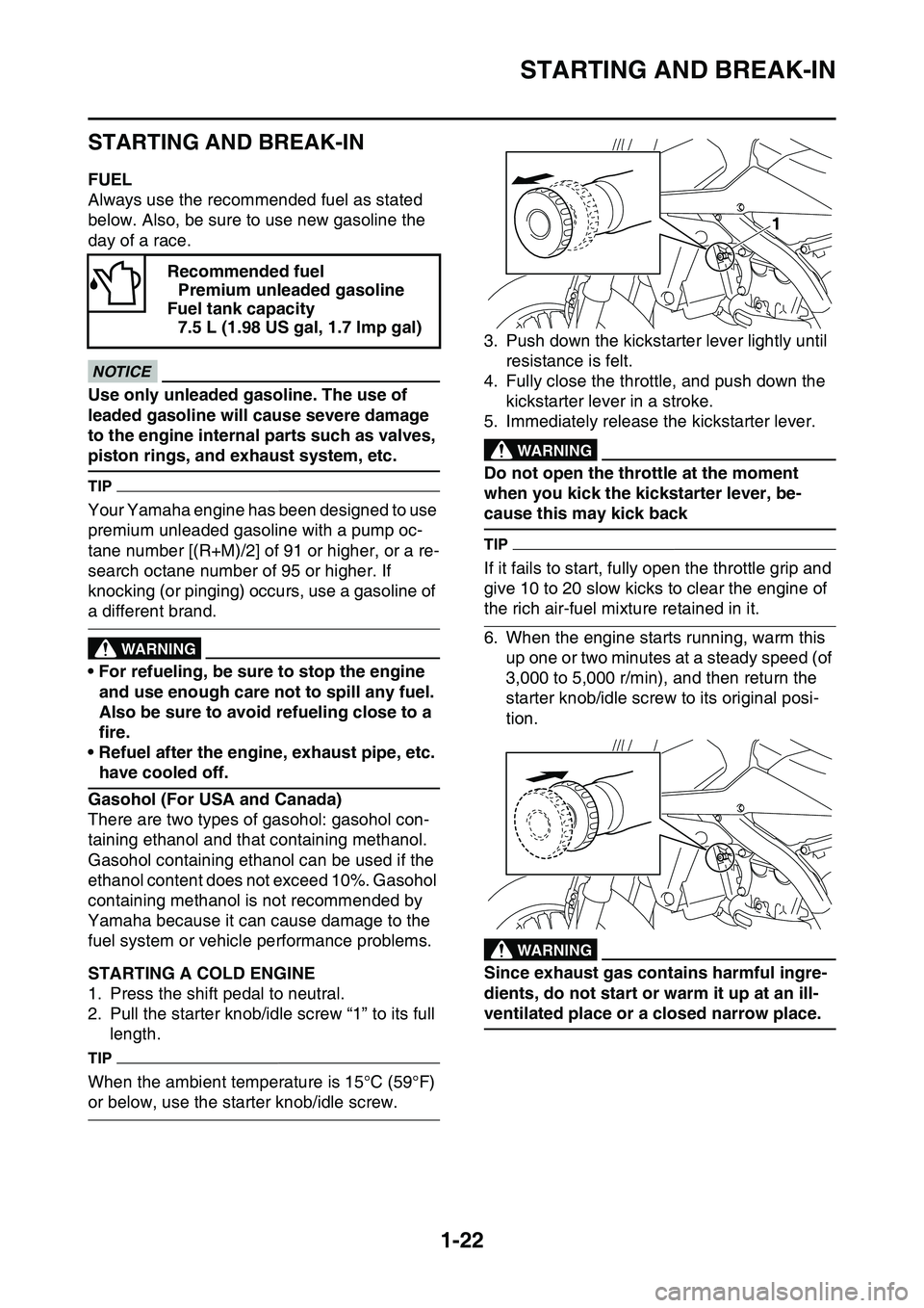
2. Pull the starter knob/idle screw “1” to its full
length.
TIP
When the ambient temperature is 15°C (59°F)
or below, use the starter knob/idle screw.
3. Push down the kickstarter lever lightly until
resistance is felt.
4. Fully close the throttle, and push down the
kickstarter lever in a stroke.
5. Immediately release the kickstarter lever.EWA
WARNING
Do not open the throttle at the moment
when you kick the kickstarter lever, be
-
cause this may kick back
TIP
If it fails to start, fully open the throttle grip and
give 10 to 20 slow kicks to clear the engine of
the rich air-fuel mixture retained in it.
6. When the engine starts running, warm this
up one or two minutes at a steady speed (of
3,000 to 5,000 r/min), and then return the
starter knob/idle screw to its original posi
-
tion.
EWA
WARNING
Since exhaust gas contains harmful ingre-
dients, do not start or warm it up at an ill-
ventilated place or a closed narrow place.
Recommended fuel
Premium unleaded gasoline
Fuel tank capacity
7.5 L (1.98 US gal, 1.7 lmp gal)
1
Page 44 of 360
GENERAL SPECIFICATIONS
2-1
EAS1SL1052
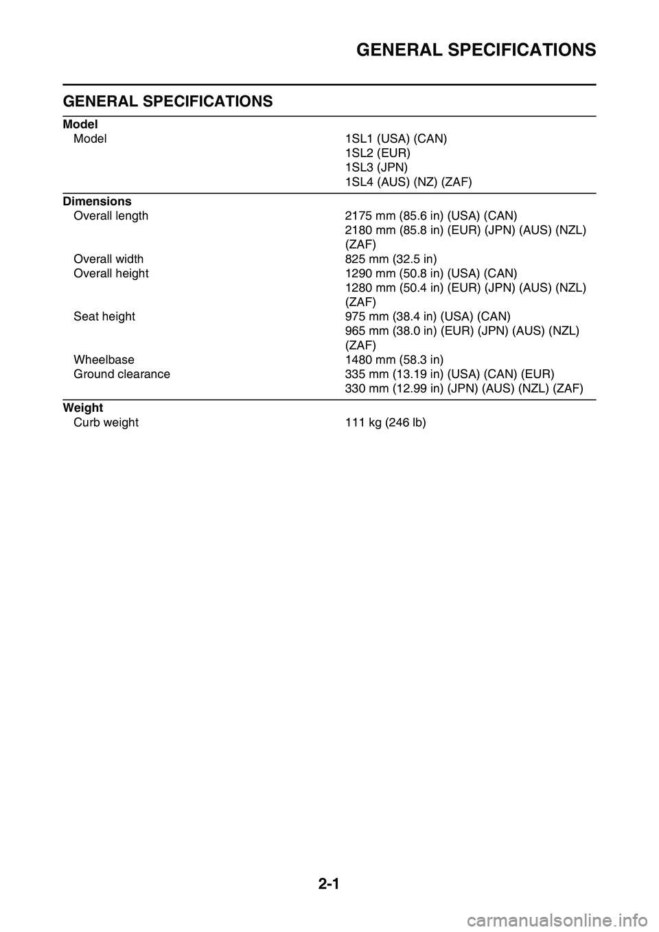
GENERAL SPECIFICATIONS
Model
Model 1SL1 (USA) (CAN)
1SL2 (EUR)
1SL3 (JPN)
1SL4 (AUS) (NZ) (ZAF)
Dimensions
Overall length 2175 mm (85.6 in) (USA) (CAN)
2180 mm (85.8 in) (EUR) (JPN) (AUS) (NZL)
(ZAF)
Overall width 825 mm (32.5 in)
Overall height 1290 mm (50.8 in) (USA) (CAN)
1280 mm (50.4 in) (EUR) (JPN) (AUS) (NZL)
(ZAF)
Seat height 975 mm (38.4 in) (USA) (CAN)
965 mm (38.0 in) (EUR) (JPN) (AUS) (NZL)
(ZAF)
Wheelbase 1480 mm (58.3 in)
Ground clearance 335 mm (13.19 in) (USA) (CAN) (EUR)
330 mm (12.99 in) (JPN) (AUS) (NZL) (ZAF)
Weight
Curb weight 111 kg (246 lb)
Page 47 of 360
ENGINE SPECIFICATIONS
2-4
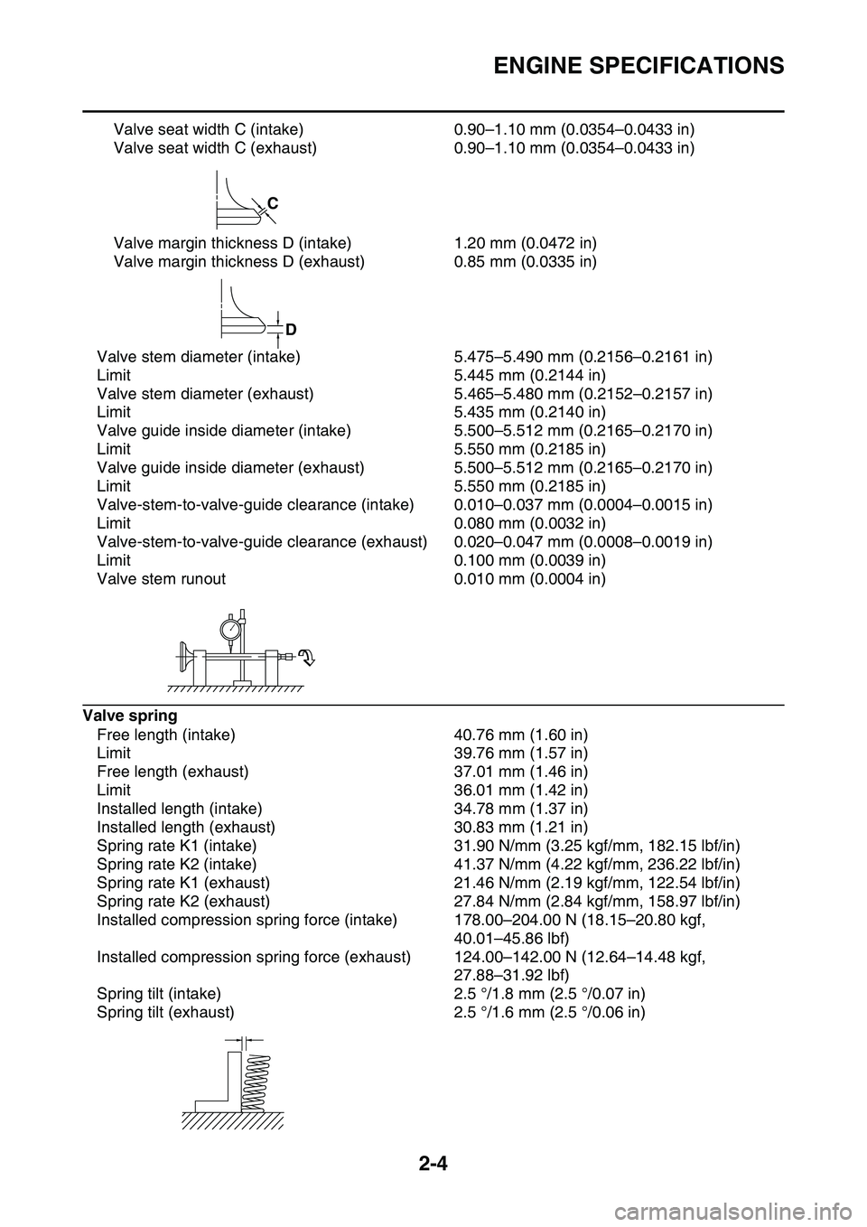
Valve seat width C (intake) 0.90–1.10 mm (0.0354–0.0433 in)
Valve seat width C (exhaust) 0.90–1.10 mm (0.0354–0.0433 in)
Valve margin thickness D (intake) 1.20 mm (0.0472 in)
Valve margin thickness D (exhaust) 0.85 mm (0.0335 in)
Valve stem diameter (intake) 5.475–5.490 mm (0.2156–0.2161 in)
Limit 5.445 mm (0.2144 in)
Valve stem diameter (exhaust) 5.465–5.480 mm (0.2152–0.2157 in)
Limit 5.435 mm (0.2140 in)
Valve guide inside diameter (intake) 5.500–5.512 mm (0.2165–0.2170 in)
Limit 5.550 mm (0.2185 in)
Valve guide inside diameter (exhaust) 5.500–5.512 mm (0.2165–0.2170 in)
Limit 5.550 mm (0.2185 in)
Valve-stem-to-valve-guide clearance (intake) 0.010–0.037 mm (0.0004–0.0015 in)
Limit 0.080 mm (0.0032 in)
Valve-stem-to-valve-guide clearance (exhaust) 0.020–0.047 mm (0.0008–0.0019 in)
Limit 0.100 mm (0.0039 in)
Valve stem runout 0.010 mm (0.0004 in)
Valve spring
Free length (intake) 40.76 mm (1.60 in)
Limit 39.76 mm (1.57 in)
Free length (exhaust) 37.01 mm (1.46 in)
Limit 36.01 mm (1.42 in)
Installed length (intake) 34.78 mm (1.37 in)
Installed length (exhaust) 30.83 mm (1.21 in)
Spring rate K1 (intake) 31.90 N/mm (3.25 kgf/mm, 182.15 lbf/in)
Spring rate K2 (intake) 41.37 N/mm (4.22 kgf/mm, 236.22 lbf/in)
Spring rate K1 (exhaust) 21.46 N/mm (2.19 kgf/mm, 122.54 lbf/in)
Spring rate K2 (exhaust) 27.84 N/mm (2.84 kgf/mm, 158.97 lbf/in)
Installed compression spring force (intake) 178.00–204.00 N (18.15–20.80 kgf,
40.01–45.86 lbf)
Installed compression spring force (exhaust) 124.00–142.00 N (12.64–14.48 kgf,
27.88–31.92 lbf)
Spring tilt (intake) 2.5 °/1.8 mm (2.5 °/0.07 in)
Spring tilt (exhaust) 2.5 °/1.6 mm (2.5 °/0.06 in)
C
D
Page 49 of 360
ENGINE SPECIFICATIONS
2-6
Oil ring
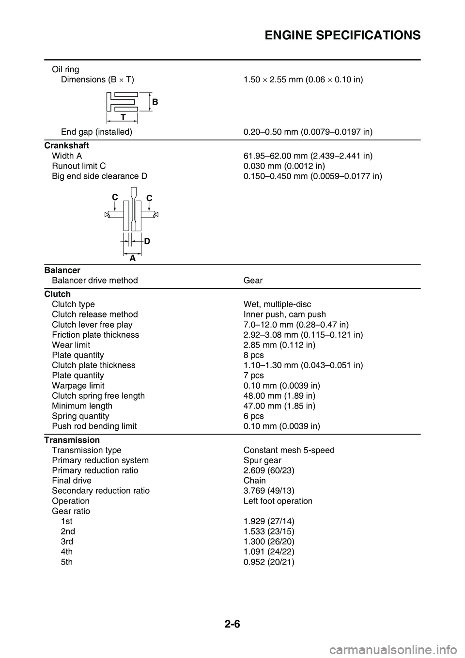
Dimensions (B T) 1.50 2.55 mm (0.06 0.10 in)
End gap (installed) 0.20–0.50 mm (0.0079–0.0197 in)
Crankshaft
Width A 61.95–62.00 mm (2.439–2.441 in)
Runout limit C 0.030 mm (0.0012 in)
Big end side clearance D 0.150–0.450 mm (0.0059–0.0177 in)
Balancer
Balancer drive method Gear
Clutch
Clutch type Wet, multiple-disc
Clutch release method Inner push, cam push
Clutch lever free play 7.0–12.0 mm (0.28–0.47 in)
Friction plate thickness 2.92–3.08 mm (0.115–0.121 in)
Wear limit 2.85 mm (0.112 in)
Plate quantity 8 pcs
Clutch plate thickness 1.10–1.30 mm (0.043–0.051 in)
Plate quantity 7 pcs
Warpage limit 0.10 mm (0.0039 in)
Clutch spring free length 48.00 mm (1.89 in)
Minimum length 47.00 mm (1.85 in)
Spring quantity 6 pcs
Push rod bending limit 0.10 mm (0.0039 in)
Transmission
Transmission type Constant mesh 5-speed
Primary reduction system Spur gear
Primary reduction ratio 2.609 (60/23)
Final drive Chain
Secondary reduction ratio 3.769 (49/13)
Operation Left foot operation
Gear ratio
1st 1.929 (27/14)
2nd 1.533 (23/15)
3rd 1.300 (26/20)
4th 1.091 (24/22)
5th 0.952 (20/21)
B
T
CC
D
A
Page 52 of 360
CHASSIS SPECIFICATIONS
2-9
Brake disc thickness limit 2.5 mm (0.10 in)
Brake pad lining thickness (inner) 4.4 mm (0.17 in)
Limit 1.0 mm (0.04 in)
Brake pad lining thickness (outer) 4.4 mm (0.17 in)
Limit 1.0 mm (0.04 in)
Master cylinder inside diameter 9.52 mm (0.37 in)
Caliper cylinder inside diameter 22.65 mm 2 (0.89 in 2)
Recommended brake fluid DOT 4
Rear brake
Type Single disc brake
Operation Right foot operation
Rear disc brake
Disc outside diameter thickness 245.0 4.0 mm (9.65 0.16 in)
Brake disc thickness limit 3.5 mm (0.14 in)
Brake disc deflection limit 0.15 mm (0.0059 in)
Brake pad lining thickness (inner) 6.4 mm (0.25 in)
Limit 1.0 mm (0.04 in)
Brake pad lining thickness (outer) 6.4 mm (0.25 in)
Limit 1.0 mm (0.04 in)
Master cylinder inside diameter 11.0 mm (0.43 in)
Caliper cylinder inside diameter 25.40 mm 1 (1.00 in 1)
Recommended fluid DOT 4
Steering
Steering bearing type Taper roller bearing
Center to lock angle (left) 43.0 °
Center to lock angle (right) 43.0 °
Front suspension
Type Telescopic fork
Spring/shock absorber type Coil spring/oil damper
Front fork travel 310.0 mm (12.20 in)
Fork spring free length 497.0 mm (19.57 in)
Limit 492.0 mm (19.37 in)
Installed length 497.0 mm (19.57 in)
Spring rate K1 4.90 N/mm (0.50 kgf/mm, 27.98 lbf/in) (USA)
(CAN)
4.70 N/mm (0.48 kgf/mm, 26.84 lbf/in) (EUR)
(JPN) (AUS) (NZL) (ZAF)
Spring stroke K1 0.0–310.0 mm (0.00–12.20 in)
Inner tube outer diameter 48.0 mm (1.89 in)
Inner tube bending limit 0.2 mm (0.01 in)
Optional spring available Yes
Recommended oil Suspension oil S1
Standard oil amount 531.0 cm3 (17.95 US.oz, 18.73 Imp.oz) (USA)
(CAN)
551.0 cm3 (18.63 US.oz, 19.43 Imp.oz) (EUR)
(JPN) (AUS) (NZL) (ZAF)
Rebound damping adjusting positions
* Position in which the adjuster is turned in finger tight
Minimum 20 click (s) out*
Standard 8 click (s) out*
Maximum (hard) Fully turned in
Page 53 of 360
CHASSIS SPECIFICATIONS
2-10
Compression damping adjusting positions
* Position in which the adjuster is turned in finger tight
Minimum 20 click (s) out*
Standard 9 click (s) out* (USA) (CAN)
8 click (s) out* (EUR) (JPN) (AUS) NZL) (ZAF)
Maximum (hard) Fully turned in
Rear suspension
Type Swingarm (link suspension)
Spring/shock absorber type Coil spring/gas-oil damper
Rear shock absorber assembly travel 132.0 mm (5.20 in)
Spring free length 275.0 mm (10.83 in)
Spring rate K1 58.00 N/mm (5.91 kgf/mm, 331.18 lbf/in) (USA)
(CAN)
56.00 N/mm (5.71 kgf/mm, 319.76 lbf/in) (EUR)
(JPN) (AUS) (NZL) (ZAF)
Spring stroke K1 0.0–150.0 mm (0.00–5.91 in)
Optional spring available Yes
Enclosed gas/air pressure (STD) 980 kPa (9.8 kgf/cm2, 139.4 psi)
Spring installed length
Minimum Position in which the spring is turned in 1.5 mm
(0.06 in) from its free length.
Standard Position in which the spring is turned in 10 mm
(0.39 in) from its free length.
Maximum Position in which the spring is turned in 18 mm
(0.71 in) from its free length.
Rebound damping adjusting positions
* Position in which the adjuster is turned in finger tight
Minimum 30 click (s) out*
Standard 14 click (s) out* (USA) (CAN)
12 click (s) out* (EUR) (JPN) (AUS) (NZL)
(ZAF)
Maximum Fully turned in
Compression damping adjusting positions
(for fast compression damping)
* Position in which the adjuster is turned in finger tight
Minimum 2 turn (s) out*
Standard 1-1/2 turn (s) out* (USA) (CAN)
1-1/8 turn (s) out* (EUR) (JPN) (AUS) (NZL)
(ZAF)
Maximum Fully turned in
Compression damping adjusting positions
(for slow compression damping)
* Position in which the adjuster is turned in finger tight
Minimum 20 click (s) out*
Standard 12 click (s) out* (USA) (CAN)
10 click (s) out* (EUR) (JPN) (AUS) (NZL)
(ZAF)
Maximum Fully turned in
Swingarm
Swingarm end free play limit (radial) 1.0 mm (0.04 in)
Swingarm end free play limit (axial) 0.2–0.9 mm (0.01–0.04 in)
Page 54 of 360
CHASSIS SPECIFICATIONS
2-11
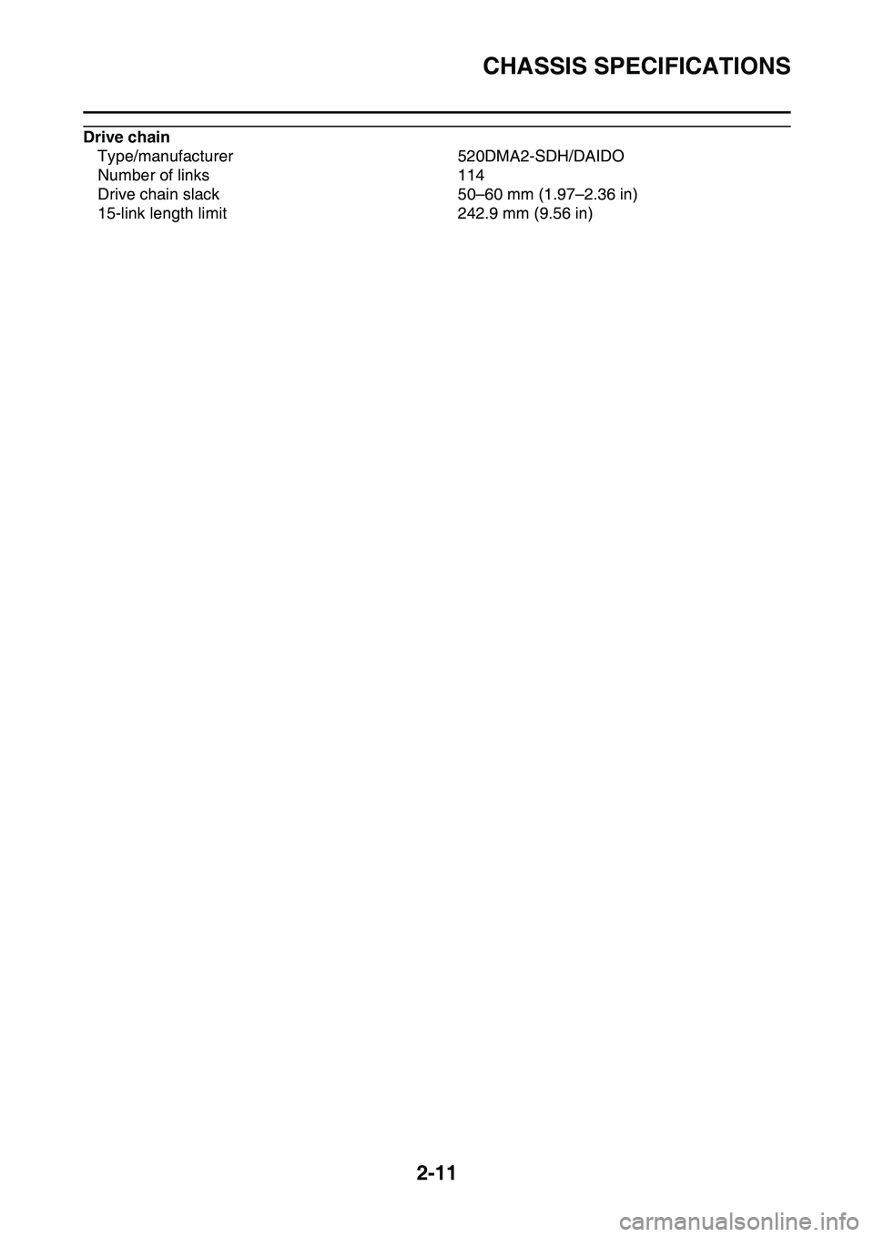
Drive chain
Type/manufacturer 520DMA2-SDH/DAIDO
Number of links 114
Drive chain slack 50–60 mm (1.97–2.36 in)
15-link length limit 242.9 mm (9.56 in)
Page 89 of 360
MAINTENANCE INTERVALS
3-1
EAS1SL1065
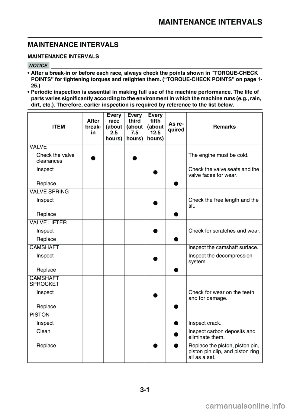
MAINTENANCE INTERVALS
EAS1SL1066MAINTENANCE INTERVALSECA@
NOTICE
• After a break-in or before each race, always check the points shown in “TORQUE-CHECK
POINTS” for tightening torques and retighten them. (
“TORQUE-CHECK POINTS” on page 1-
25.)
• Periodic inspection is essential in making full use of the machine performance. The life of
parts varies significantly according to the environment in which the machine runs (e.g., rain,
dirt, etc.). Therefore, earlier inspection is required by reference to the list below.
ITEM
After
break-
in
Every
race
(about
2.5
hours)Every
third
(about
7.5
hours)Every
fifth
(about
12.5
hours)
As re-
quiredRemarks
VALVE
Check the valve
clearancesThe engine must be cold.
InspectCheck the valve seats and the
valve faces for wear.
Replace
VALVE SPRING
InspectCheck the free length and the
tilt.
Replace
VALVE LIFTER
InspectCheck for scratches and wear.
Replace
CAMSHAFTInspect the camshaft surface.
InspectInspect the decompression
system.
Replace
CAMSHAFT
SPROCKET
InspectCheck for wear on the teeth
and for damage.
Replace
PISTON
InspectInspect crack.
CleanInspect carbon deposits and
eliminate them.
ReplaceReplace the piston, piston pin,
piston pin clip, and piston ring
all as a set.