YAMAHA YZ450F 2015 Owners Manual
Manufacturer: YAMAHA, Model Year: 2015, Model line: YZ450F, Model: YAMAHA YZ450F 2015Pages: 360, PDF Size: 10.82 MB
Page 351 of 360
CHASSIS
10-4
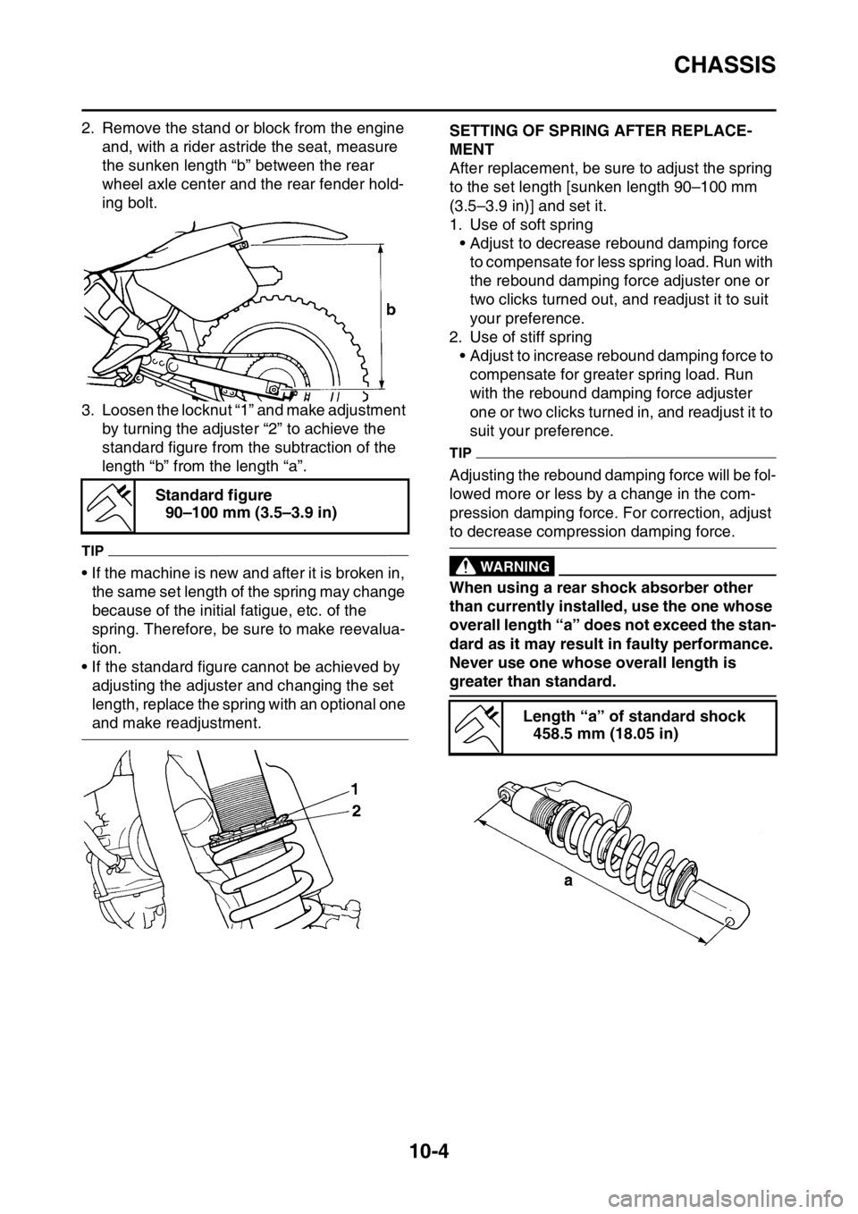
2. Remove the stand or block from the engine
and, with a rider astride the seat, measure
the sunken length “b” between the rear
wheel axle center and the rear fender hold-
ing bolt.
3. Loosen the locknut “1” and make adjustment
by turning the adjuster “2” to achieve the
standard figure from the subtraction of the
length “b” from the length “a”.
TIP
• If the machine is new and after it is broken in,
the same set length of the spring may change
because of the initial fatigue, etc. of the
spring. Therefore, be sure to make reevalua-
tion.
• If the standard figure cannot be achieved by
adjusting the adjuster and changing the set
length, replace the spring with an optional one
and make readjustment.
EAS1SL5376SETTING OF SPRING AFTER REPLACE-
MENT
After replacement, be sure to adjust the spring
to the set length [sunken length 90–100 mm
(3.5–3.9 in)] and set it.
1. Use of soft spring
• Adjust to decrease rebound damping force
to compensate for less spring load. Run with
the rebound damping force adjuster one or
two clicks turned out, and readjust it to suit
your preference.
2. Use of stiff spring
• Adjust to increase rebound damping force to
compensate for greater spring load. Run
with the rebound damping force adjuster
one or two clicks turned in, and readjust it to
suit your preference.
TIP
Adjusting the rebound damping force will be fol-
lowed more or less by a change in the com-
pression damping force. For correction, adjust
to decrease compression damping force.
EWA1DX4002
WARNING
When using a rear shock absorber other
than currently installed, use the one whose
overall length “a” does not exceed the stan-
dard as it may result in faulty performance.
Never use one whose overall length is
greater than standard. Standard figure
90–100 mm (3.5–3.9 in)
Length “a” of standard shock
458.5 mm (18.05 in)
Page 352 of 360
CHASSIS
10-5
EAS1SL5377REAR SHOCK ABSORBER SETTING
PARTS
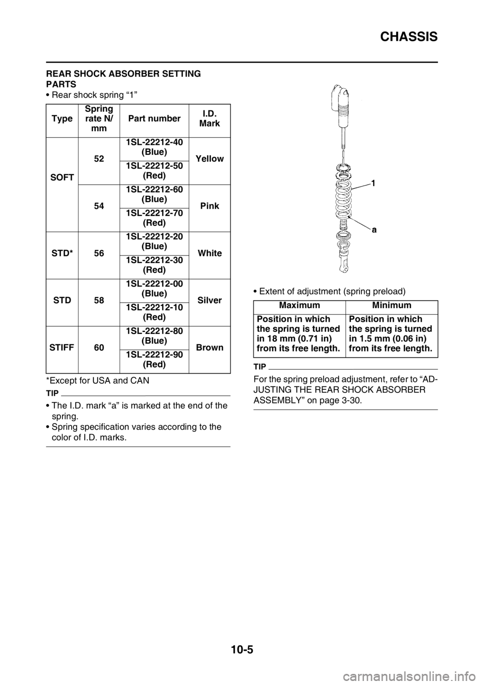
• Rear shock spring “1”
*Except for USA and CAN
TIP
• The I.D. mark “a” is marked at the end of the
spring.
• Spring specification varies according to the
color of I.D. marks.• Extent of adjustment (spring preload)
TIP
For the spring preload adjustment, refer to “AD-
JUSTING THE REAR SHOCK ABSORBER
ASSEMBLY” on page 3-30. TypeSpring
rate N/
mmPart numberI.D.
Mark
SOFT521SL-22212-40
(Blue)
Yellow
1SL-22212-50
(Red)
541SL-22212-60
(Blue)
Pink
1SL-22212-70
(Red)
STD* 561SL-22212-20
(Blue)
White
1SL-22212-30
(Red)
STD 581SL-22212-00
(Blue)
Silver
1SL-22212-10
(Red)
STIFF 601SL-22212-80
(Blue)
Brown
1SL-22212-90
(Red)
Maximum Minimum
Position in which
the spring is turned
in 18 mm (0.71 in)
from its free length.Position in which
the spring is turned
in 1.5 mm (0.06 in)
from its free length.
Page 353 of 360
CHASSIS
10-6
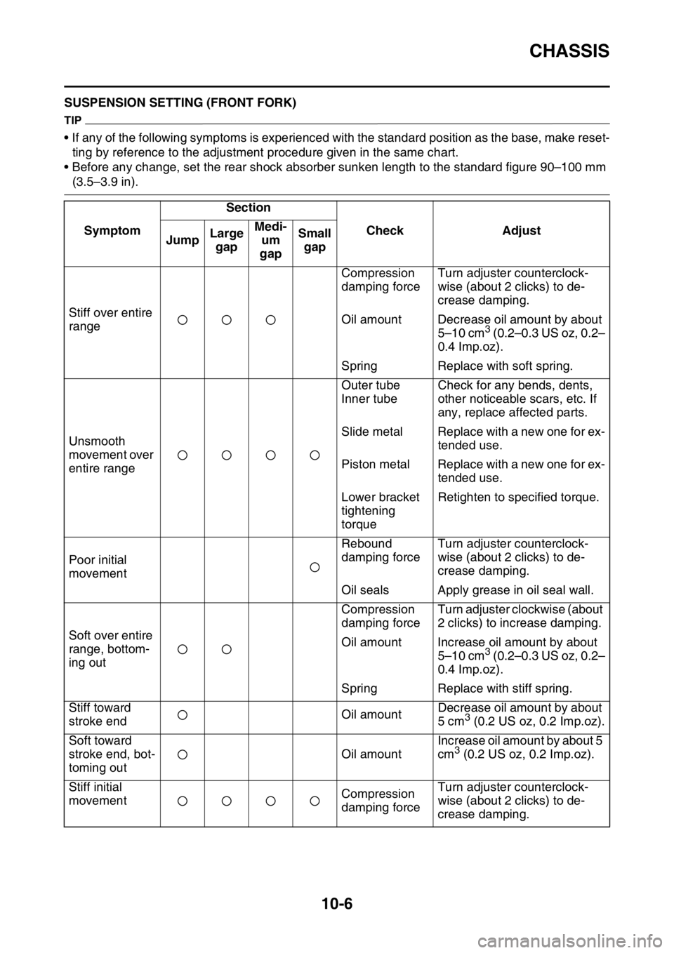
EAS1SL5378SUSPENSION SETTING (FRONT FORK)
TIP
• If any of the following symptoms is experienced with the standard position as the base, make reset-
ting by reference to the adjustment procedure given in the same chart.
• Before any change, set the rear shock absorber sunken length to the standard figure 90–100 mm
(3.5–3.9 in).
SymptomSection
Check Adjust
JumpLarge
gapMedi-
um
gapSmall
gap
Stiff over entire
rangeCompression
damping forceTurn adjuster counterclock-
wise (about 2 clicks) to de-
crease damping.
Oil amount Decrease oil amount by about
5–10 cm
3 (0.2–0.3 US oz, 0.2–
0.4 Imp.oz).
Spring Replace with soft spring.
Unsmooth
movement over
entire rangeOuter tube
Inner tubeCheck for any bends, dents,
other noticeable scars, etc. If
any, replace affected parts.
Slide metal Replace with a new one for ex-
tended use.
Piston metal Replace with a new one for ex-
tended use.
Lower bracket
tightening
torqueRetighten to specified torque.
Poor initial
movementRebound
damping forceTurn adjuster counterclock-
wise (about 2 clicks) to de-
crease damping.
Oil seals Apply grease in oil seal wall.
Soft over entire
range, bottom-
ing outCompression
damping forceTurn adjuster clockwise (about
2 clicks) to increase damping.
Oil amount Increase oil amount by about
5–10 cm
3 (0.2–0.3 US oz, 0.2–
0.4 Imp.oz).
Spring Replace with stiff spring.
Stiff toward
stroke endOil amountDecrease oil amount by about
5 cm
3 (0.2 US oz, 0.2 Imp.oz).
Soft toward
stroke end, bot-
toming outOil amountIncrease oil amount by about 5
cm
3 (0.2 US oz, 0.2 Imp.oz).
Stiff initial
movementCompression
damping forceTurn adjuster counterclock-
wise (about 2 clicks) to de-
crease damping.
Page 354 of 360
CHASSIS
10-7
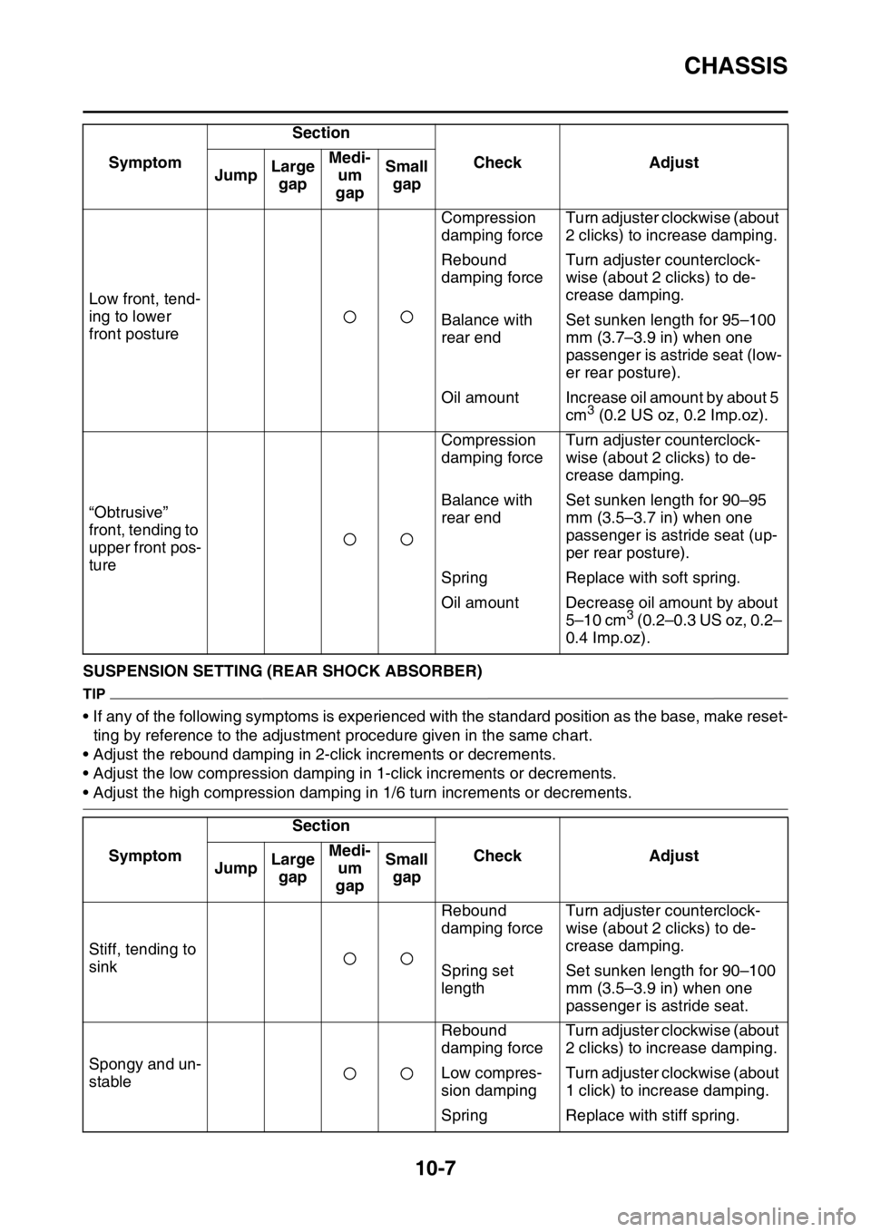
EAS1SL5379SUSPENSION SETTING (REAR SHOCK ABSORBER)
TIP
• If any of the following symptoms is experienced with the standard position as the base, make reset-
ting by reference to the adjustment procedure given in the same chart.
• Adjust the rebound damping in 2-click increments or decrements.
• Adjust the low compression damping in 1-click increments or decrements.
• Adjust the high compression damping in 1/6 turn increments or decrements. Low front, tend-
ing to lower
front postureCompression
damping forceTurn adjuster clockwise (about
2 clicks) to increase damping.
Rebound
damping forceTurn adjuster counterclock-
wise (about 2 clicks) to de-
crease damping.
Balance with
rear endSet sunken length for 95–100
mm (3.7–3.9 in) when one
passenger is astride seat (low-
er rear posture).
Oil amount Increase oil amount by about 5
cm
3 (0.2 US oz, 0.2 Imp.oz).
“Obtrusive”
front, tending to
upper front pos-
tureCompression
damping forceTurn adjuster counterclock-
wise (about 2 clicks) to de-
crease damping.
Balance with
rear endSet sunken length for 90–95
mm (3.5–3.7 in) when one
passenger is astride seat (up-
per rear posture).
Spring Replace with soft spring.
Oil amount Decrease oil amount by about
5–10 cm
3 (0.2–0.3 US oz, 0.2–
0.4 Imp.oz).
SymptomSection
Check Adjust
JumpLarge
gapMedi-
um
gapSmall
gap
Stiff, tending to
sinkRebound
damping forceTurn adjuster counterclock-
wise (about 2 clicks) to de-
crease damping.
Spring set
lengthSet sunken length for 90–100
mm (3.5–3.9 in) when one
passenger is astride seat.
Spongy and un-
stableRebound
damping forceTurn adjuster clockwise (about
2 clicks) to increase damping.
Low compres-
sion dampingTurn adjuster clockwise (about
1 click) to increase damping.
Spring Replace with stiff spring. SymptomSection
Check Adjust
JumpLarge
gapMedi-
um
gapSmall
gap
Page 355 of 360

CHASSIS
10-8
Heavy and
draggingRebound
damping forceTurn adjuster counterclock-
wise (about 2 clicks) to de-
crease damping.
Spring Replace with soft spring.
Poor road grip-
pingRebound
damping forceTurn adjuster counterclock-
wise (about 2 clicks) to de-
crease damping.
Low compres-
sion dampingTurn adjuster clockwise (about
1 click) to increase damping.
High compres-
sion dampingTurn adjuster clockwise (about
1/6 turn) to increase damping.
Spring set
lengthSet sunken length for 90–100
mm (3.5–3.9 in) when one
passenger is astride seat.
Spring Replace with soft spring.
Bottoming outHigh compres-
sion dampingTurn adjuster clockwise (about
1/6 turn) to increase damping.
Spring set
lengthSet sunken length for 90–100
mm (3.5–3.9 in) when one
passenger is astride seat.
Spring Replace with stiff spring.
BouncingRebound
damping forceTurn adjuster clockwise (about
2 clicks) to increase damping.
Spring Replace with soft spring.
Stiff travelHigh compres-
sion dampingTurn adjuster counterclock-
wise (about 1/6 turn) to de-
crease damping.
Spring set
lengthSet sunken length for 90–100
mm (3.5–3.9 in) when one
passenger is astride seat.
Spring Replace with soft spring. SymptomSection
Check Adjust
JumpLarge
gapMedi-
um
gapSmall
gap
Page 356 of 360

EAS1SL5381
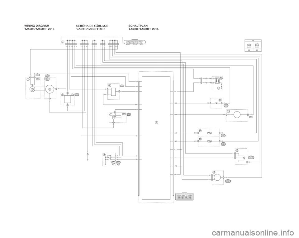
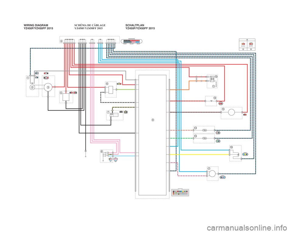
WIRING DIAGRAM
YZ450F/YZ450FF 2015
1. Crankshaft position sensor
2. AC magneto
3. Rectifier/regulator
4. Joint connector
5. Condenser
6. Coupler for connecting option-
al part
7. Engine stop switch
8. Neutral switch
9. ECU
10. Ignition coil
11. Spark plug
12. Injector
13. Fuel pump
14. Intake air temperature sensor
15. Coolant temperature sensor
16. Throttle position sensor
17. Intake air pressure sensor
EAS1SL5382COLOR CODE
BBlack
Gy Gray
LBlue
Lg Light green
O Orange
PPink
RRed
Sb Sky blue
Y Yellow
B/L Black/Blue
B/R Black/Red
B/W Black/White
B/Y Black/Yellow
Br/W Brown/White
G/W Green/White
P/B Pink/Black
R/B Red/Black
Page 357 of 360

Page 358 of 360

PRINTED IN JAPAN(E)PRINTED ON RECYCLED PAPER
Page 359 of 360
A
A
A
A
B
R R R R R R RB
B
B
R
RRLgLg
B/W
B/YB/Y
B
B
B
PPPSb
B/L
P/B
P/B
Y
L
Y
L
L
G/W
Br/W
G/W
Br/WB/L
B/L
B/L
B/L
B/RB/R
R/BR/B
O
O
R
O
R
O
R
R
R
Sb
B
Gy
R
B/W
P
LB/L
B/L Gy B/L
B/LB/LB/LB/L
L L
P P
B B B B
4
1
32
5
\f
7
8
10
\b
12
11
13
14
15
1\f
17
P P
Sb
R B
B/RR
R
B
B/L
GyBR
B/Y PSb
B B
RR/B
L YB/L
B/W R
Lg
B/LBr/W
B/L P/B L
B/LG/W
BB/Y
B
B/L B/L
B/L B/L B/L B/LB BB B R R
P P PL L L
R R
R R R
B
O P
Gy
R
B/Y S bP/B
R/B Lg B/RG/WBr/WB/L L
Y
R BB/LGy
ROOR(BLA
CK) (BLACK)
B/W
WIRING DIAGRAM
YZ450F/YZ450FF 2015 SCHÉMA DE CÂBLAGE
YZ450F/YZ450FF 2015
SCHALTPLAN
YZ450F/YZ450FF 2015
1SL-28199-81_W.D.indd 12014/03/07 10:18:57
Page 360 of 360
A
A
A
A
B
(BLA CK) (BLACK)
4
1
32
5
6
7
8
10
9
12
11
13
14
15
16
17
WIRING DIAGRAM
YZ450F/YZ450FF 2015 SCHÉMA DE CÂBLAGE
YZ450F/YZ450FF 2015
SCHALTPLAN
YZ450F/YZ450FF 2015
1SL-28199-81_W.D.indd 22014/03/07 10:18:57