gas type YAMAHA YZ450F 2015 Owners Manual
[x] Cancel search | Manufacturer: YAMAHA, Model Year: 2015, Model line: YZ450F, Model: YAMAHA YZ450F 2015Pages: 360, PDF Size: 10.82 MB
Page 36 of 360

STARTING AND BREAK-IN
1-22
EAS1SL5042
STARTING AND BREAK-IN
EAS1SL5043FUEL
Always use the recommended fuel as stated
below. Also, be sure to use new gasoline the
day of a race.
JCA
NOTICE
Use only unleaded gasoline. The use of
leaded gasoline will cause severe damage
to the engine internal parts such as valves,
piston rings, and exhaust system, etc.
TIP
Your Yamaha engine has been designed to use
premium unleaded gasoline with a pump oc-
tane number [(R+M)/2] of 91 or higher, or a re-
search octane number of 95 or higher. If
knocking (or pinging) occurs, use a gasoline of
a different brand.
JWA
WARNING
• For refueling, be sure to stop the engine
and use enough care not to spill any fuel.
Also be sure to avoid refueling close to a
fire.
• Refuel after the engine, exhaust pipe, etc.
have cooled off.
Gasohol (For USA and Canada)
There are two types of gasohol: gasohol con-
taining ethanol and that containing methanol.
Gasohol containing ethanol can be used if the
ethanol content does not exceed 10%. Gasohol
containing methanol is not recommended by
Yamaha because it can cause damage to the
fuel system or vehicle performance problems.
EAS1SL5044STARTING A COLD ENGINE
1. Press the shift pedal to neutral.
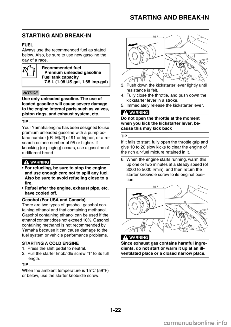
2. Pull the starter knob/idle screw “1” to its full
length.
TIP
When the ambient temperature is 15°C (59°F)
or below, use the starter knob/idle screw.3. Push down the kickstarter lever lightly until
resistance is felt.
4. Fully close the throttle, and push down the
kickstarter lever in a stroke.
5. Immediately release the kickstarter lever.
EWA
WARNING
Do not open the throttle at the moment
when you kick the kickstarter lever, be-
cause this may kick back
TIP
If it fails to start, fully open the throttle grip and
give 10 to 20 slow kicks to clear the engine of
the rich air-fuel mixture retained in it.
6. When the engine starts running, warm this
up one or two minutes at a steady speed (of
3000 to 5000 r/min), and then return the
starter knob/idle screw to its original posi-
tion.
EWA
WARNING
Since exhaust gas contains harmful ingre-
dients, do not start or warm it up at an ill-
ventilated place or a closed narrow place. Recommended fuel
Premium unleaded gasoline
Fuel tank capacity
7.5 L (1.98 US gal, 1.65 lmp.gal)
1
Page 45 of 360

ENGINE SPECIFICATIONS
2-2
EAS1SL5054
ENGINE SPECIFICATIONS
Engine
Engine type Liquid cooled 4-stroke, DOHC
Displacement 450 cm
3
Cylinder arrangement Single cylinder
Bore stroke 97.0 60.8 mm (3.8 2.4 in)
Compression ratio 12.5:1
Starting system Kickstarter
Fuel
Recommended fuel Premium unleaded gasoline only
Fuel tank capacity 7.5 L (1.98 US gal, 1.65 Imp.gal)
Engine oil
Lubrication system Wet sump
Recommended brand YAMALUBE
Type SAE 10W-30, SAE 10W-40, SAE 15W-40, SAE
20W-40 or SAE 20W-50
Recommended oil grade API service SG type or higher, JASO standard
MA
Engine oil quantity
Quantity (disassembled) 0.95 L (1.00 US qt, 0.84 Imp.qt)
With oil filter element replacement 0.69 L (0.73 US qt, 0.61 Imp.qt)
Without oil filter element replacement 0.67 L (0.71 US qt, 0.59 Imp.qt)
Oil filter
Oil filter type Paper
Oil pump
Oil pump type Trochoid
Inner-rotor-to-outer-rotor-tip clearance Less than 0.150 mm (0.0059 in)
Limit 0.20 mm (0.0079 in)
Outer-rotor-to-oil-pump-housing clearance 0.13–0.18 mm (0.0051–0.0071 in)
Limit 0.24 mm (0.0094 in)
Oil-pump-housing-to-inner-and-outer-rotor
clearance 0.06–0.11 mm (0.0024–0.0043 in)
Limit 0.17 mm (0.0067 in)
Cooling system
Radiator capacity (including all routes) 1.04 L (1.10 US qt, 0.92 Imp.qt)
Radiator capacity 0.57 L (0.60 US qt, 0.50 mp.qt)
Radiator cap opening pressure 108–137 kPa (1.08–1.37 kg/cm
2, 15.7–19.9
psi)
Radiator core
Width 112.6 mm (4.43 in)
Height 235.0 mm (9.25 in)
Depth 28.0 mm (1.10 in)
Water pump
Water pump type Single suction centrifugal pump
Spark plug
Manufacturer/model NGK/CR8E
Spark plug gap 0.7–0.8 mm (0.028–0.031 in)
Page 53 of 360

CHASSIS SPECIFICATIONS
2-10
Compression damping adjusting positions
* Position in which the adjuster is turned in finger tight
Minimum 20 click (s) out*
Standard 8 click (s) out*
Maximum (hard) Fully turned in
Rear suspension
Type Swingarm (link suspension)
Spring/shock absorber type Coil spring/gas-oil damper
Rear shock absorber assembly travel 132.0 mm (5.20 in)
Spring free length 275.0 mm (10.83 in)
Spring rate K1 58.00 N/mm (5.91 kgf/mm, 331.18 lbf/in) (USA)
(CAN)
56.00 N/mm (5.71 kgf/mm, 319.76 lbf/in) (EUR)
(JPN) (AUS) (NZL) (ZAF)
Spring stroke K1 0.0–150.0 mm (0.00–5.91 in)
Optional spring available Yes
Enclosed gas/air pressure (STD) 980 kPa (9.8 kgf/cm
2, 139.4 psi)
Spring installed length
Minimum Position in which the spring is turned in 1.5 mm
(0.06 in) from its free length.
Standard Position in which the spring is turned in 10 mm
(0.39 in) from its free length.
Maximum Position in which the spring is turned in 18 mm
(0.71 in) from its free length.
Rebound damping adjusting positions
* Position in which the adjuster is turned in finger tight
Minimum 30 click (s) out*
Standard 14 click (s) out* (USA) (CAN)
12 click (s) out* (EUR) (JPN) (AUS) (NZL)
(ZAF)
Maximum Fully turned in
Compression damping adjusting positions
(for fast compression damping)
* Position in which the adjuster is turned in finger tight
Minimum 2 turn (s) out*
Standard 1-1/2 turn (s) out* (USA) (CAN)
1-1/8 turn (s) out* (EUR) (JPN) (AUS) (NZL)
(ZAF)
Maximum Fully turned in
Compression damping adjusting positions
(for slow compression damping)
* Position in which the adjuster is turned in finger tight
Minimum 20 click (s) out*
Standard 12 click (s) out* (USA) (CAN)
10 click (s) out* (EUR) (JPN) (AUS) (NZL)
(ZAF)
Maximum Fully turned in
Swingarm
Swingarm end free play limit (radial) 1.0 mm (0.04 in)
Swingarm end free play limit (axial) 0.2–0.9 mm (0.01–0.04 in)
Page 64 of 360

LUBRICATION POINTS AND LUBRICANT TYPES
2-21
EAS1SL5060
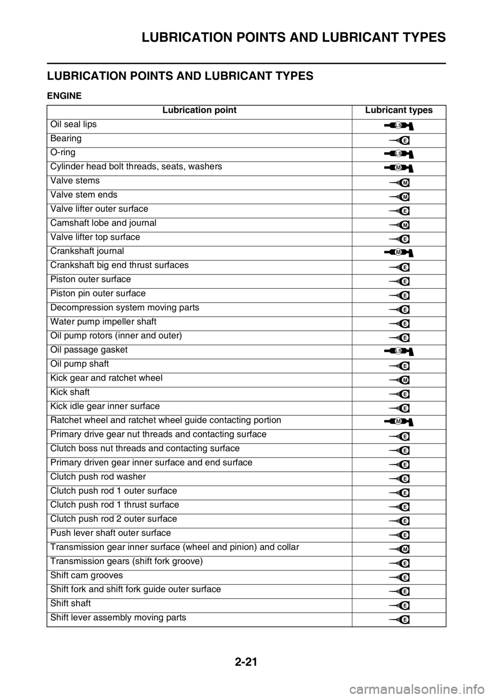
LUBRICATION POINTS AND LUBRICANT TYPES
EAS1SL5061ENGINE
Lubrication point Lubricant types
Oil seal lips
Bearing
O-ring
Cylinder head bolt threads, seats, washers
Valve stems
Valve stem ends
Valve lifter outer surface
Camshaft lobe and journal
Valve lifter top surface
Crankshaft journal
Crankshaft big end thrust surfaces
Piston outer surface
Piston pin outer surface
Decompression system moving parts
Water pump impeller shaft
Oil pump rotors (inner and outer)
Oil passage gasket
Oil pump shaft
Kick gear and ratchet wheel
Kick shaft
Kick idle gear inner surface
Ratchet wheel and ratchet wheel guide contacting portion
Primary drive gear nut threads and contacting surface
Clutch boss nut threads and contacting surface
Primary driven gear inner surface and end surface
Clutch push rod washer
Clutch push rod 1 outer surface
Clutch push rod 1 thrust surface
Clutch push rod 2 outer surface
Push lever shaft outer surface
Transmission gear inner surface (wheel and pinion) and collar
Transmission gears (shift fork groove)
Shift cam grooves
Shift fork and shift fork guide outer surface
Shift shaft
Shift lever assembly moving parts
LS
E
LS
M
M
M
E
M
E
M
E
E
E
E
E
E
LS
E
M
E
E
M
E
E
E
E
E
E
E
E
M
E
E
E
E
E
Page 65 of 360

LUBRICATION POINTS AND LUBRICANT TYPES
2-22
Cylinder head cover gasketThree Bond
No.1215®
Crankcase mating surfaceThree Bond
No.1215®
Stator assembly lead grommetThree Bond
No.1215® Lubrication point Lubricant types
Page 123 of 360

ELECTRICAL SYSTEM
3-35
EAS1SL5115
ELECTRICAL SYSTEM
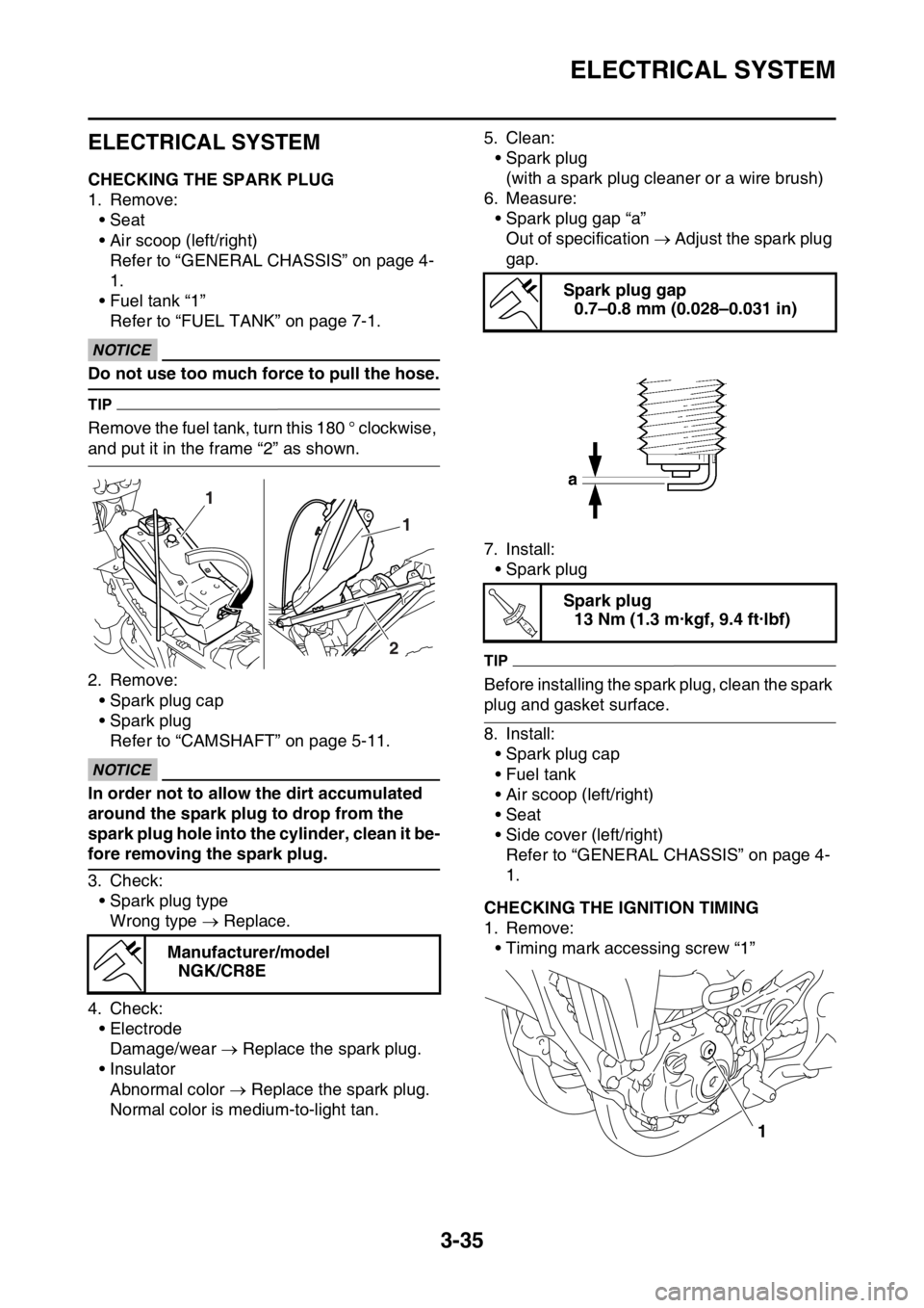
EAS1SL5116CHECKING THE SPARK PLUG
1. Remove:
• Seat
• Air scoop (left/right)
Refer to “GENERAL CHASSIS” on page 4-
1.
• Fuel tank “1”
Refer to “FUEL TANK” on page 7-1.
ECA1DX1001
NOTICE
Do not use too much force to pull the hose.
TIP
Remove the fuel tank, turn this 180 ° clockwise,
and put it in the frame “2” as shown.
2. Remove:
• Spark plug cap
• Spark plug
Refer to “CAMSHAFT” on page 5-11.
ECA13330
NOTICE
In order not to allow the dirt accumulated
around the spark plug to drop from the
spark plug hole into the cylinder, clean it be-
fore removing the spark plug.
3. Check:
• Spark plug type
Wrong type Replace.
4. Check:
• Electrode
Damage/wear Replace the spark plug.
• Insulator
Abnormal color Replace the spark plug.
Normal color is medium-to-light tan.5. Clean:
• Spark plug
(with a spark plug cleaner or a wire brush)
6. Measure:
• Spark plug gap “a”
Out of specification Adjust the spark plug
gap.
7. Install:
• Spark plug
TIP
Before installing the spark plug, clean the spark
plug and gasket surface.
8. Install:
• Spark plug cap
• Fuel tank
• Air scoop (left/right)
• Seat
• Side cover (left/right)
Refer to “GENERAL CHASSIS” on page 4-
1.
EAS1SL5117CHECKING THE IGNITION TIMING
1. Remove:
• Timing mark accessing screw “1”
Manufacturer/model
NGK/CR8E
1
1
2
Spark plug gap
0.7–0.8 mm (0.028–0.031 in)
Spark plug
13 Nm (1.3 m·kgf, 9.4 ft·lbf)
T R..
1