checking oil YAMAHA YZ450F 2016 Owner's Manual
[x] Cancel search | Manufacturer: YAMAHA, Model Year: 2016, Model line: YZ450F, Model: YAMAHA YZ450F 2016Pages: 362, PDF Size: 10.49 MB
Page 231 of 362

CYLINDER AND PISTON
5-36
TIP
The oil ring expander’s end gap cannot be
measured. If the oil ring rail’s gap is excessive,
replace all three oil rings.
EASB111229CHECKING THE PISTON PIN
1. Check:
• Piston pin
Blue discoloration/grooves Replace the
piston pin and then check the lubrication
system.
2. Measure:
• Piston pin outside diameter “a”
Out of specification Replace the piston
pin.3. Measure:
• Piston pin bore inside diameter “b”
Out of specification Replace the piston.EASB111230INSTALLING THE PISTON AND CYLINDER
1. Install:
• Oil ring expander “1”
• Lower oil ring rail “2”
• Upper oil ring rail “3”
• 2nd ring “4”
• Top ring “5”
TIP
Be sure to install the piston rings so that the
manufacturer’s marks or numbers face up. Piston ring
Top ring
End gap (installed)
0.20–0.30 mm (0.0079–0.0118 in)
Limit
0.55 mm (0.0217 in)
2nd ring
End gap (installed)
0.35–0.50 mm (0.0138–0.0197 in)
Limit
0.85 mm (0.0335 in)
Oil ring
End gap (installed)
0.20–0.50 mm (0.0079–0.0197 in)
Piston pin outside diameter
17.991–18.000 mm (0.7083–
0.7087 in)
Limit
17.971 mm (0.7075 in)
Piston pin bore inside diameter
18.004–18.015 mm (0.7088–
0.7093 in)
Limit
18.045 mm (0.7104 in)
b
Page 238 of 362

CLUTCH
5-43
2. Check:
• Primary-drive-gear-to-primary-driven-gear
free play
Free play exists Replace the primary
drive and primary driven gears as a set.
EASB111242CHECKING THE PRIMARY DRIVEN GEAR
1. Check:
• Primary driven gear
Damage/wear Replace the primary drive
and primary driven gears as a set.
Excessive noise during operation Re-
place the primary drive and primary driven
gears as a set.
EASB111243INSTALLING THE OIL SEAL
1. Install:
• Oil seal “1”
• Washer “2”
• Circlip “3”
TIP
• Apply is lithium-soap-based grease on the oil
seal lip.
• Install the oil seal in parallel with its manufac-
ture's marks or numbers facing inward.
EASB111244INSTALLING THE RIGHT CRANKCASE
COVER
1. Install:
• Dowel pin “1”
• O-rings “2”
• Collar “3”
• Gasket “4”
TIP
Apply the lithium-soap-based grease on the O-
ring.2. Install:
• Right crankcase cover “1”
• Right crankcase cover bolt “2”
TIP
• Apply the engine oil on the impeller shaft end.
• When installing the crankcase cover onto the
crankcase, make sure that the impeller shaft
end “3” aligns with the balancer end slot “4”.
• Tighten the right crankcase cover bolts in
stages and in a crisscross pattern.
New
New
3
2
1
LS
New
New
Right crankcase cover bolt
10 Nm (1.0 m·kgf, 7.2 ft·lbf)
1
1 4
2
New
New
3
LS
T R..
12
Page 243 of 362

KICKSTATER
5-48
EASB111248REMOVING THE KICK SHAFT ASSEMBLY
1. Remove:
• Kick shaft assembly “1”
TIP
Unhook the torsion spring “2” from the hole “a”
in the crankcase.
EASB111249CHECKING THE KICK SHAFT AND RATCH-
ET WHEEL
1. Check:
• Ratchet wheel “1” smooth movement
Unsmooth movement Replace.
• Kick shaft “2”
Wear/damage Replace the kick shaft as-
sembly.
• Spring “3”
Broken Replace.
EASB111250CHECKING THE KICK GEAR, KICK IDLE
GEAR AND RATCHET WHEEL
1. Check:
• Kick gear “1”
Wear/damage Replace the kick shaft as-
sembly.
• Kick idle gear “2”
• Ratchet wheel “3”
• Gear teeth “a”
• Ratchet teeth “b”
Wear/damage Replace.
EASB111251INSTALLING THE KICK SHAFT ASSEMBLY
1. Install:
• Kick gear “1”
• Washer “2”
• Circlip “3”
• Ratchet wheel “4”
• Spring “5”
• Washer “6”
• Circlip “7”
(to the kick shaft “8”)
TIP
• Apply molybdenum disulfide oil to the inner
circumferences of the kick gear and ratchet
wheel.
• Align the punch mark “a” on the ratchet wheel
with the punch mark “b” on the kick shaft.
2. Install:
• Torsion spring “1”
(to the kick shaft “2”)
TIP
Make sure the stopper “a” of the torsion spring
fits into the hole “b” on the kick shaft.
31
2
a
b
3
12
New
New
Page 252 of 362

OIL PUMP AND BALANCER GEAR
5-57
EASB111265REMOVING THE BALANCER
1. Straighten the lock washer tab.
2. Loosen:
• Balancer nut “1”
• Primary drive gear nut “2”
• Balancer weight gear nut “3”
TIP
Place an aluminum plate “a” between the teeth
of the balancer drive gear “4” and balancer
weight gear “5”.
EASB111266CHECKING THE PRIMARY DRIVE GEAR,
BALANCER SHAFT DRIVE GEAR, AND
BALANCER WEIGHT GEAR
1. Check:
• Primary drive gear “1”
• Balancer shaft drive gear “2”
• Balancer weight gear “3”
Wear/damage Replace.
EASB111267CHECKING THE BALANCER
1. Check:
•Balancer
Crack/damage Replace.
EASB111268CHECKING THE OIL PUMP
1. Check:
• Oil pump drive gear
• Oil pump driven gear
• Oil pump housing
• Oil pump housing cover
Cracks/damage/wear Replace the defec-
tive part(s).
2. Measure:
• Inner-rotor-to-outer-rotor-tip clearance “a”
• Outer-rotor-to-oil-pump-housing clearance
“b”
• Oil-pump-housing-to-inner-rotor-and-outer-
rotor clearance “c”
Out of specification Replace the oil pump.
1
5
4
2
a
43
a
5
Page 262 of 362
CRANKCASE
5-67
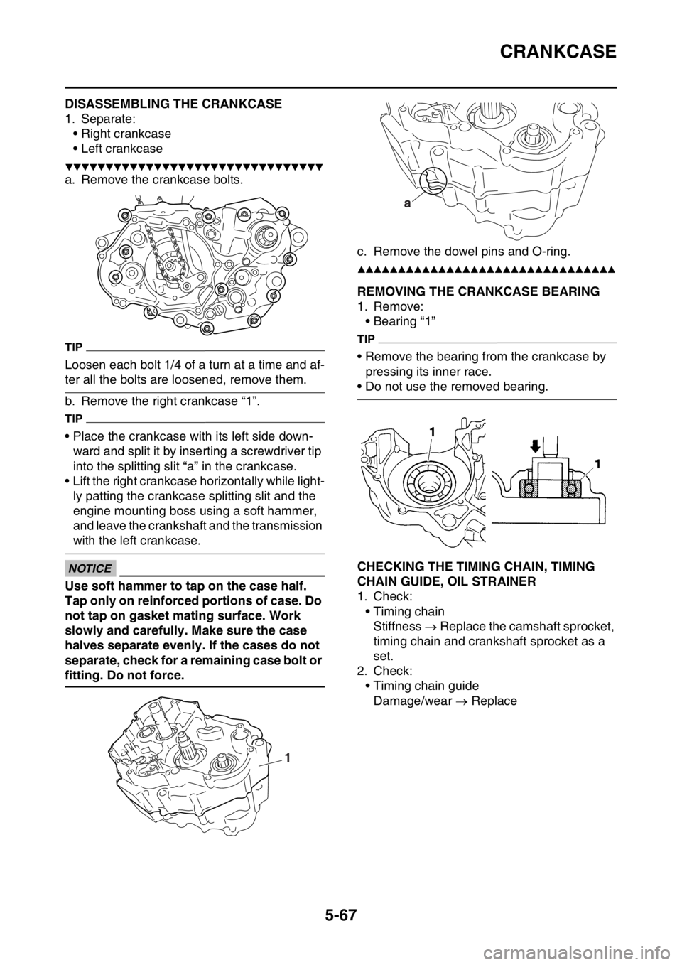
EASB111277DISASSEMBLING THE CRANKCASE
1. Separate:
• Right crankcase
• Left crankcase
▼▼▼▼▼▼▼▼▼▼▼▼▼▼▼▼▼▼▼▼▼▼▼▼▼▼▼▼▼▼▼▼
a. Remove the crankcase bolts.
TIP
Loosen each bolt 1/4 of a turn at a time and af-
ter all the bolts are loosened, remove them.
b. Remove the right crankcase “1”.
TIP
• Place the crankcase with its left side down-
ward and split it by inserting a screwdriver tip
into the splitting slit “a” in the crankcase.
• Lift the right crankcase horizontally while light-
ly patting the crankcase splitting slit and the
engine mounting boss using a soft hammer,
and leave the crankshaft and the transmission
with the left crankcase.
ECA33DD041
NOTICE
Use soft hammer to tap on the case half.
Tap only on reinforced portions of case. Do
not tap on gasket mating surface. Work
slowly and carefully. Make sure the case
halves separate evenly. If the cases do not
separate, check for a remaining case bolt or
fitting. Do not force.c. Remove the dowel pins and O-ring.
▲▲▲▲▲▲▲▲▲▲▲▲▲▲▲▲▲▲▲▲▲▲▲▲▲▲▲▲▲▲▲▲
EASB111278REMOVING THE CRANKCASE BEARING
1. Remove:
• Bearing “1”
TIP
• Remove the bearing from the crankcase by
pressing its inner race.
• Do not use the removed bearing.
EASB111279CHECKING THE TIMING CHAIN, TIMING
CHAIN GUIDE, OIL STRAINER
1. Check:
• Timing chain
Stiffness Replace the camshaft sprocket,
timing chain and crankshaft sprocket as a
set.
2. Check:
• Timing chain guide
Damage/wear Replace
1
a
Page 263 of 362
CRANKCASE
5-68
EASB111280CHECKING THE CRANKCASE
1. Wash:
• Crankcase
TIP
• Wash the crankcase in a mild solvent.
• Remove any remaining gasket from the
crankcase mating surface.
2. Check:
• Crankcase
Crack/damage Replace.
• Oil delivery passages
Obstruction Blow out with compressed
air.
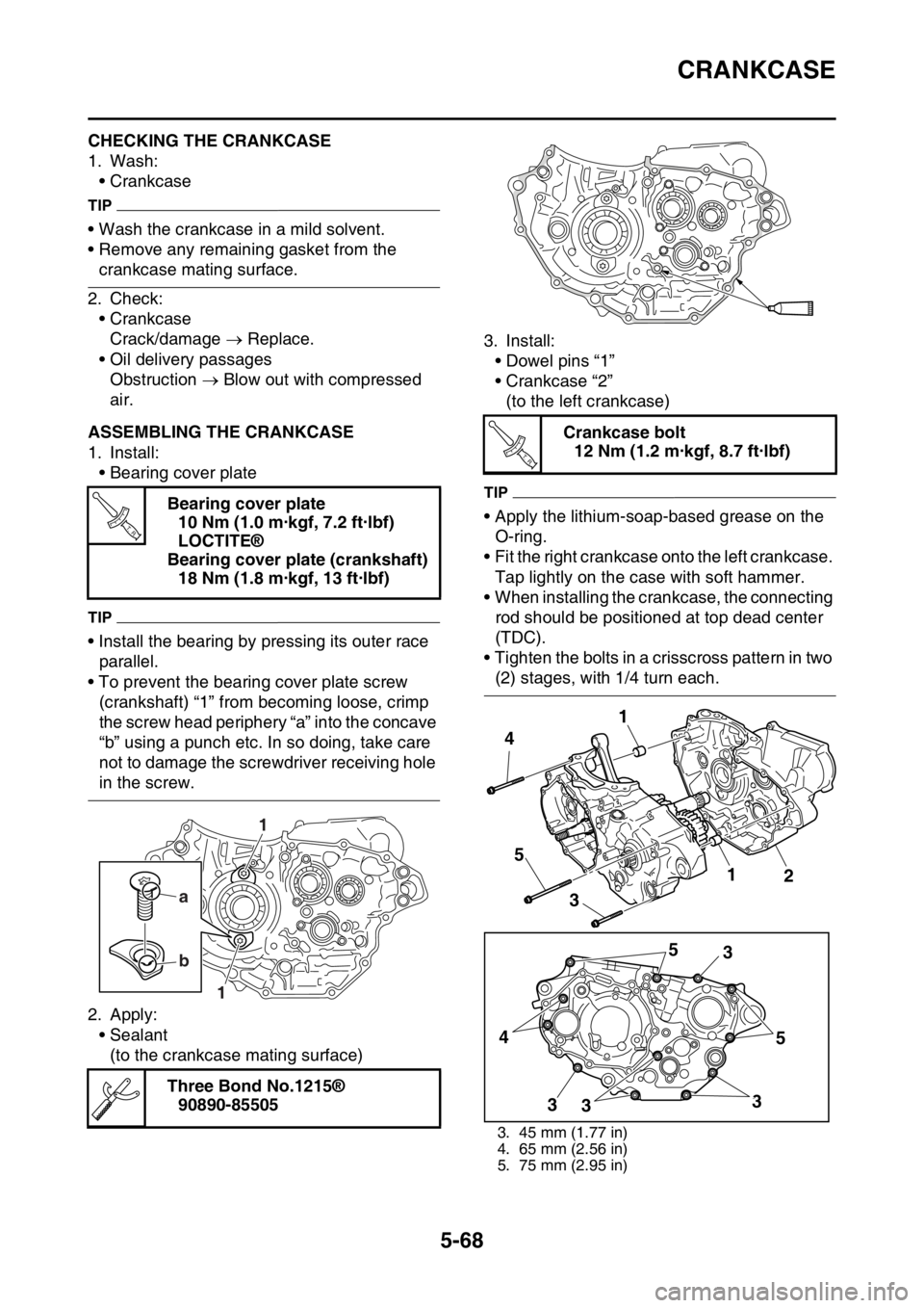
EASB111281ASSEMBLING THE CRANKCASE
1. Install:
• Bearing cover plate
TIP
• Install the bearing by pressing its outer race
parallel.
• To prevent the bearing cover plate screw
(crankshaft) “1” from becoming loose, crimp
the screw head periphery “a” into the concave
“b” using a punch etc. In so doing, take care
not to damage the screwdriver receiving hole
in the screw.
2. Apply:
• Sealant
(to the crankcase mating surface)3. Install:
• Dowel pins “1”
• Crankcase “2”
(to the left crankcase)
TIP
• Apply the lithium-soap-based grease on the
O-ring.
• Fit the right crankcase onto the left crankcase.
Tap lightly on the case with soft hammer.
• When installing the crankcase, the connecting
rod should be positioned at top dead center
(TDC).
• Tighten the bolts in a crisscross pattern in two
(2) stages, with 1/4 turn each. Bearing cover plate
10 Nm (1.0 m·kgf, 7.2 ft·lbf)
LOCTITE®
Bearing cover plate (crankshaft)
18 Nm (1.8 m·kgf, 13 ft·lbf)
Three Bond No.1215®
90890-85505
T R..
a
b
1
1
Crankcase bolt
12 Nm (1.2 m·kgf, 8.7 ft·lbf)
3. 45 mm (1.77 in)
4. 65 mm (2.56 in)
5. 75 mm (2.95 in)
T R..
5
3
5
3
3 3 45 4
3
1
12
Page 269 of 362
TRANSMISSION
5-74
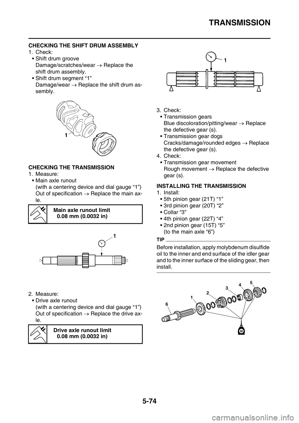
EASB111290CHECKING THE SHIFT DRUM ASSEMBLY
1. Check:
• Shift drum groove
Damage/scratches/wear Replace the
shift drum assembly.
• Shift drum segment “1”
Damage/wear Replace the shift drum as-
sembly.
EASB111291CHECKING THE TRANSMISSION
1. Measure:
• Main axle runout
(with a centering device and dial gauge “1”)
Out of specification Replace the main ax-
le.
2. Measure:
• Drive axle runout
(with a centering device and dial gauge “1”)
Out of specification Replace the drive ax-
le.3. Check:
• Transmission gears
Blue discoloration/pitting/wear Replace
the defective gear (s).
• Transmission gear dogs
Cracks/damage/rounded edges Replace
the defective gear (s).
4. Check:
• Transmission gear movement
Rough movement Replace the defective
gear (s).
EASB111292INSTALLING THE TRANSMISSION
1. Install:
• 5th pinion gear (21T) “1”
• 3rd pinion gear (20T) “2”
• Collar “3”
• 4th pinion gear (22T) “4”
• 2nd pinion gear (15T) “5”
(to the main axle “6”)
TIP
Before installation, apply molybdenum disulfide
oil to the inner and end surface of the idler gear
and to the inner surface of the sliding gear, then
install. Main axle runout limit
0.08 mm (0.0032 in)
Drive axle runout limit
0.08 mm (0.0032 in)
34
2
1
6
5
M
Page 273 of 362

6
COOLING SYSTEM
RADIATOR....................................................................................................... 6-1
HANDLING NOTE ...................................................................................... 6-3
CHECKING THE RADIATOR ..................................................................... 6-3
WATER PUMP.................................................................................................. 6-4
REMOVING THE OIL SEAL ....................................................................... 6-5
CHECKING THE WATER PUMP ............................................................... 6-5
CHECKING THE BEARING....................................................................... 6-5
INSTALLING THE OIL SEAL..................................................................... 6-5
ASSEMBLING THE WATER PUMP........................................................... 6-5
Page 278 of 362
WATER PUMP
6-5
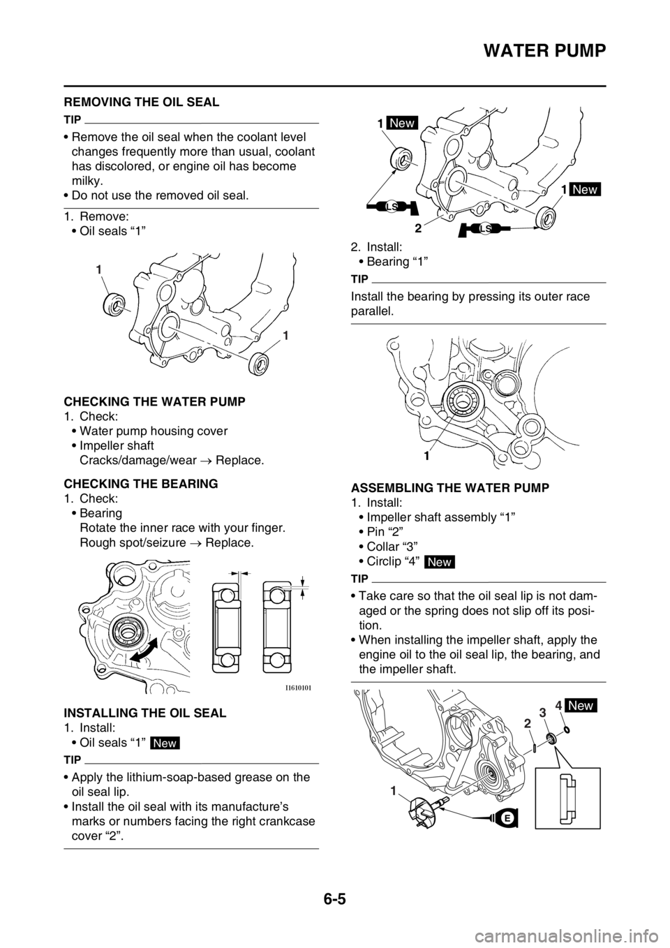
EASB111298REMOVING THE OIL SEAL
TIP
• Remove the oil seal when the coolant level
changes frequently more than usual, coolant
has discolored, or engine oil has become
milky.
• Do not use the removed oil seal.
1. Remove:
• Oil seals “1”
EASB111299CHECKING THE WATER PUMP
1. Check:
• Water pump housing cover
• Impeller shaft
Cracks/damage/wear Replace.
EASB111300CHECKING THE BEARING
1. Check:
• Bearing
Rotate the inner race with your finger.
Rough spot/seizure Replace.
EASB111301INSTALLING THE OIL SEAL
1. Install:
• Oil seals “1”
TIP
• Apply the lithium-soap-based grease on the
oil seal lip.
• Install the oil seal with its manufacture’s
marks or numbers facing the right crankcase
cover “2”.2. Install:
• Bearing “1”
TIP
Install the bearing by pressing its outer race
parallel.
EASB111302ASSEMBLING THE WATER PUMP
1. Install:
• Impeller shaft assembly “1”
•Pin “2”
• Collar “3”
• Circlip “4”
TIP
• Take care so that the oil seal lip is not dam-
aged or the spring does not slip off its posi-
tion.
• When installing the impeller shaft, apply the
engine oil to the oil seal lip, the bearing, and
the impeller shaft.
1 1
New
1 1New
New
LS
LS2
New
4
1
23New
E
Page 291 of 362
8
ELECTRICAL SYSTEM
IGNITION SYSTEM.......................................................................................... 8-2
CIRCUIT DIAGRAM ................................................................................... 8-2
TROUBLESHOOTING ............................................................................... 8-4
CHARGING SYSTEM....................................................................................... 8-6
CIRCUIT DIAGRAM ................................................................................... 8-6
TROUBLESHOOTING ............................................................................... 8-8
FUEL INJECTION SYSTEM........................................................................... 8-10
CIRCUIT DIAGRAM ................................................................................. 8-10
YAMAHA DIAGNOSTIC TOOL ................................................................ 8-12
TROUBLESHOOTING DETAILS ............................................................. 8-13
FUEL PUMP SYSTEM.................................................................................... 8-32
CIRCUIT DIAGRAM ................................................................................. 8-32
TROUBLESHOOTING ............................................................................. 8-34
ELECTRICAL COMPONENTS....................................................................... 8-36
CHECKING THE SWITCHES .................................................................. 8-38
CHECKING THE IGNITION SPARK GAP................................................ 8-41
CHECKING THE SPARK PLUG CAP ...................................................... 8-41
CHECKING THE IGNITION COIL ............................................................ 8-41
CHECKING THE CRANKSHAFT POSITION SENSOR........................... 8-42
CHECKING THE ECU .............................................................................. 8-42
CHECKING THE STATOR COIL ............................................................. 8-42
CHECKING THE RECTIFIER/REGULATOR ........................................... 8-43
CHECKING THE COOLANT TEMPERATURE SENSOR........................ 8-43
CHECKING THE THROTTLE POSITION SENSOR ................................ 8-44
CHECKING THE THROTTLE POSITION SENSOR INPUT VOLTAGE .. 8-45
CHECKING THE INTAKE AIR PRESSURE SENSOR ............................ 8-45
CHECKING THE INTAKE AIR TEMPERATURE SENSOR ..................... 8-45
CHECKING THE NEUTRAL SWITCH ..................................................... 8-46
CHECKING THE FUEL INJECTOR ......................................................... 8-46