stop YAMAHA YZ65 2022 Owners Manual
[x] Cancel search | Manufacturer: YAMAHA, Model Year: 2022, Model line: YZ65, Model: YAMAHA YZ65 2022Pages: 92, PDF Size: 5.19 MB
Page 24 of 92
Description
3-1
3
EAU63371
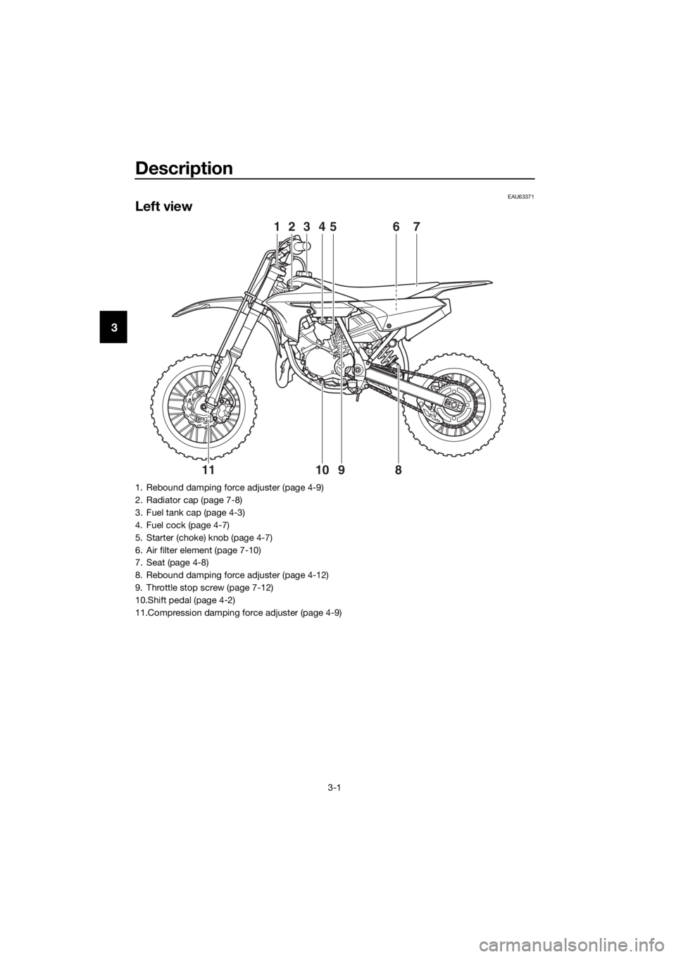
Left view
6745231
981011
1. Rebound damping force adjuster (page 4-9)
2. Radiator cap (page 7-8)
3. Fuel tank cap (page 4-3)
4. Fuel cock (page 4-7)
5. Starter (choke) knob (page 4-7)
6. Air filter element (page 7-10)
7. Seat (page 4-8)
8. Rebound damping force adjuster (page 4-12)
9. Throttle stop screw (page 7-12)
10.Shift pedal (page 4-2)
11.Compression damping force adjuster (page 4-9)
UBR882E0.book Page 1 Wednesday, February 26, 2020 11:39 AM
Page 26 of 92
Description
3-3
3
EAU63401
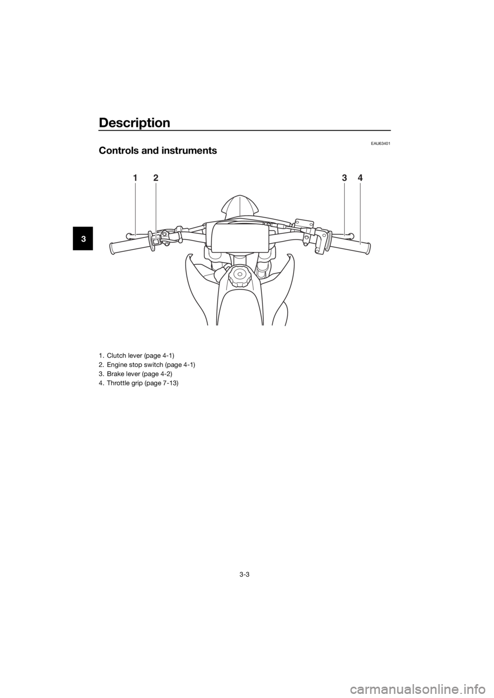
Controls and instruments
1324
1. Clutch lever (page 4-1)
2. Engine stop switch (page 4-1)
3. Brake lever (page 4-2)
4. Throttle grip (page 7-13)
UBR882E0.book Page 3 Wednesd ay, February 26, 2020 11:39 AM
Page 27 of 92
Instrument and control functions
4-1
4
EAU40661
Han dle bar switch
EAU53962En gine stop switch “ENGINE STOP”
Hold this switch pushed until the en-
gine stops.
EAU64023
Clutch lever
The clutch lever is located on the left
side of the handlebar. To disengage
the clutch, pull the lever toward the
handlebar grip. To engage the clutch,
release the lever. The lever should be
pulled rapidly and released slowly for
smooth clutch operation.
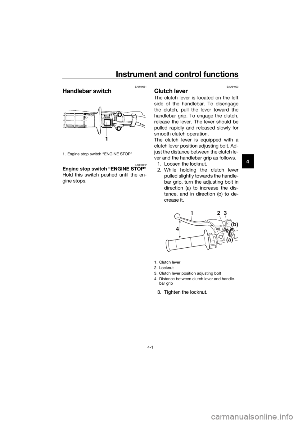
The clutch lever is equipped with a
clutch lever position adjusting bolt. Ad-
just the distance between the clutch le-
ver and the handlebar grip as follows. 1. Loosen the locknut.
2. While holding the clutch lever pulled slightly towards the handle-
bar grip, turn the adjusting bolt in
direction (a) to increase the dis-
tance, and in direction (b) to de-
crease it.
3. Tighten the locknut.
1. Engine stop switch “ENGINE STOP”
1. Clutch lever
2. Locknut
3. Clutch lever position adjusting bolt
4. Distance between clutch lever and handle- bar grip
4 2
13
(b)
(a)
UBR882E0.book Page 1 Wednesd
ay, February 26, 2020 11:39 AM
Page 31 of 92
![YAMAHA YZ65 2022 Owners Manual Instrument and control functions
4-5
4
Gasoline
This model’s engine is designed to use
premium unleaded gasoline with a
pump octane number [(R+M)/2] of 91
or higher, or a research octane number
(RON YAMAHA YZ65 2022 Owners Manual Instrument and control functions
4-5
4
Gasoline
This model’s engine is designed to use
premium unleaded gasoline with a
pump octane number [(R+M)/2] of 91
or higher, or a research octane number
(RON](/img/51/54005/w960_54005-30.png)
Instrument and control functions
4-5
4
Gasoline
This model’s engine is designed to use
premium unleaded gasoline with a
pump octane number [(R+M)/2] of 91
or higher, or a research octane number
(RON) of 95 or higher. If knocking or
pinging occurs, try a gasoline of a dif-
ferent brand.
NOTICE
ECA15591
Use only unlea
ded g asoline. The use
of lead ed g asoline will cause severe
d ama ge to internal en gine parts,
such as the piston rin gs as well as to
the exhaust system.
Gasohol
There are two types of gasohol: gaso-
hol containing ethanol and that con-
taining methanol. Gasohol containing
ethanol can be used if the ethanol con-
tent does not exceed 10% (E10). Gas-
ohol containing methanol should not
be used as it can cause engine or fuel
system problems.
Fillin g the fuel tank
WARNING
EWA10882
Gasoline an d gasoline vapors are
extremely flamma ble. To avoi d fires
an d explosions an d to re duce the
risk of injury when refueling , follow
these instructions.
1. Before refueling, turn off the en- gine and be sure that no one is sit-
ting on the vehicle. Never refuel
while smoking, or while in the vi-
cinity of sparks, open flames, or
other sources of ignition such as
the pilot lights of water heaters
and clothes dryers.
2. Do not overfill the fuel tank. Stop filling when the fuel reaches the
bottom of the filler tube. Because
fuel expands when it heats up,
heat from the engine or the sun
can cause fuel to spill out of the
fuel tank.
3. Wipe up any spilled fuel immedi- ately. NOTICE: Immediately
wipe off spille d fuel with a clean,
d ry, soft cloth, since fuel may
d eteriorate painte d surfaces or
plastic parts.
[ECA10072]
4. Be sure to securely close the fuel tank cap.
WARNING
EWA15152
Gasoline is poisonous an d can
cause injury or death. Han dle gaso-
line with care. Never siphon gasoline
b y mouth. If you shoul d swallow
some gasoline or inhale a lot of gas-
oline vapor, or get some gasoline in
your eyes, see your d octor immedi-
ately. If g asoline spills on your skin,
1. Maximum fuel level
2. Fuel tank filler tube
12
UBR882E0.book Page 5 Wednesd ay, February 26, 2020 11:39 AM
Page 35 of 92
Instrument and control functions
4-9
4
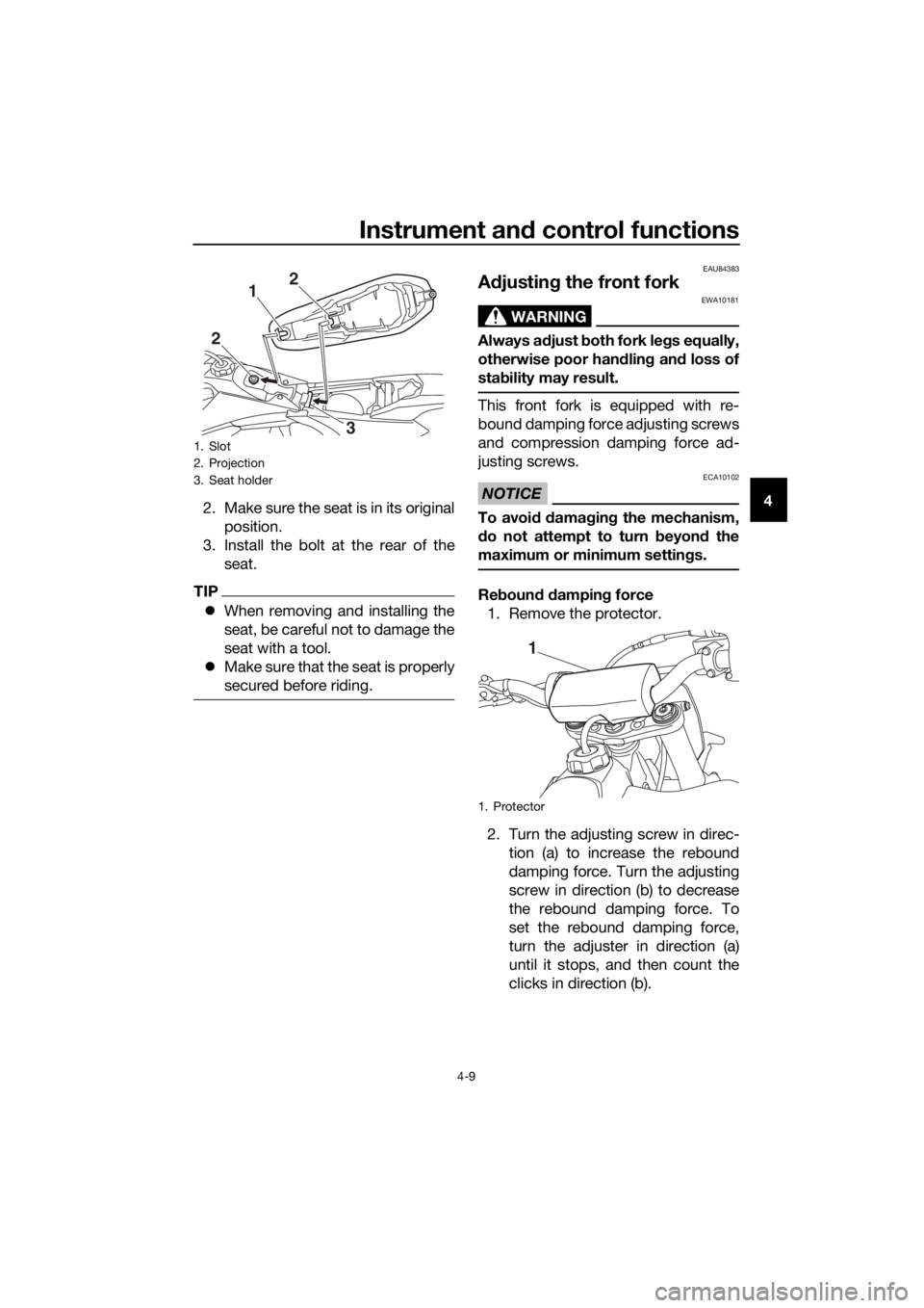
2. Make sure the seat is in its original
position.
3. Install the bolt at the rear of the seat.
TIP
When removing and installing the
seat, be careful not to damage the
seat with a tool.
Make sure that the seat is properly
secured before riding.
EAU84383
Adjustin g the front fork
WARNING
EWA10181
Always a djust both fork le gs equally,
otherwise poor han dlin g an d loss of
stab ility may result.
This front fork is equipped with re-
bound damping force adjusting screws
and compression damping force ad-
justing screws.
NOTICE
ECA10102
To avoi d d amag ing the mechanism,
d o not attempt to turn b eyond the
maximum or minimum settin gs.
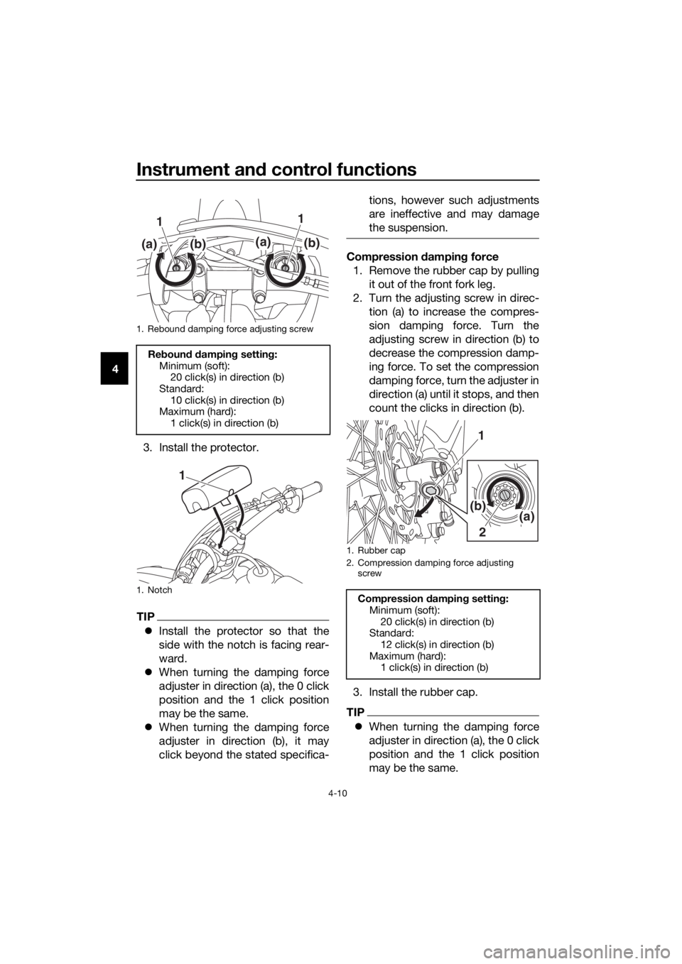
Re boun d d ampin g force
1. Remove the protector.
2. Turn the adjusting screw in direc- tion (a) to increase the rebound
damping force. Turn the adjusting
screw in direction (b) to decrease
the rebound damping force. To
set the rebound damping force,
turn the adjuster in direction (a)
until it stops, and then count the
clicks in direction (b).
1. Slot
2. Projection
3. Seat holder
3
2
1
2
1. Protector
1
UBR882E0.book Page 9 Wednesd
ay, February 26, 2020 11:39 AM
Page 36 of 92
Instrument and control functions
4-10
4
3. Install the protector.
TIP
Install the protector so that the
side with the notch is facing rear-
ward.
When turning the damping force
adjuster in direction (a), the 0 click
position and the 1 click position
may be the same.
When turning the damping force
adjuster in direction (b), it may
click beyond the stated specifica- tions, however such adjustments
are ineffective and may damage
the suspension.
Compression
dampin g force
1. Remove the rubber cap by pulling it out of the front fork leg.
2. Turn the adjusting screw in direc- tion (a) to increase the compres-
sion damping force. Turn the
adjusting screw in direction (b) to
decrease the compression damp-
ing force. To set the compression
damping force, turn the adjuster in
direction (a) until it stops, and then
count the clicks in direction (b).
3. Install the rubber cap.
TIP
When turning the damping force
adjuster in direction (a), the 0 click
position and the 1 click position
may be the same.
1. Rebound damping force adjusting screw
Reboun d d ampin g setting :
Minimum (soft): 20 click(s) in direction (b)
Standard: 10 click(s) in direction (b)
Maximum (hard):
1 click(s) in direction (b)
1. Notch
1 1
(a)
(b)(a)(b)
1
1. Rubber cap
2. Compression damping force adjusting screw
Compression dampin g settin g:
Minimum (soft): 20 click(s) in direction (b)
Standard:
12 click(s) in direction (b)
Maximum (hard): 1 click(s) in direction (b)
2
1
(a)(b)
UBR882E0.book Page 10 Wednesday, February 26, 2020 11:39 AM
Page 40 of 92
Instrument and control functions
4-14
4
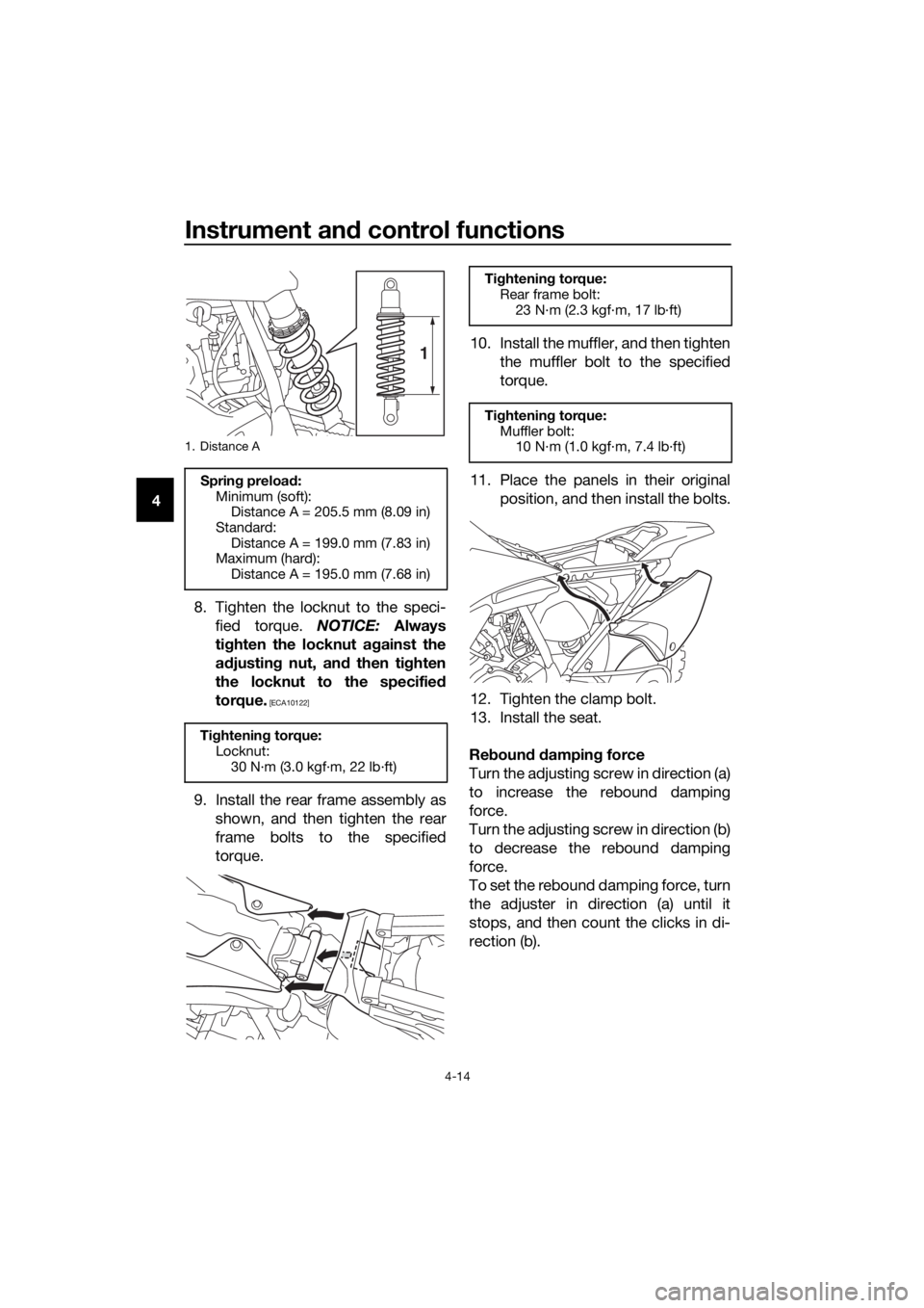
8. Tighten the locknut to the speci-fied torque. NOTICE: Always
ti g hten the locknut ag ainst the
a d justin g nut, and then tighten
the locknut to the specified
torque.
[ECA10122]
9. Install the rear frame assembly as shown, and then tighten the rear
frame bolts to the specified
torque. 10. Install the muffler, and then tighten
the muffler bolt to the specified
torque.
11. Place the panels in their original position, and then install the bolts.
12. Tighten the clamp bolt.
13. Install the seat.
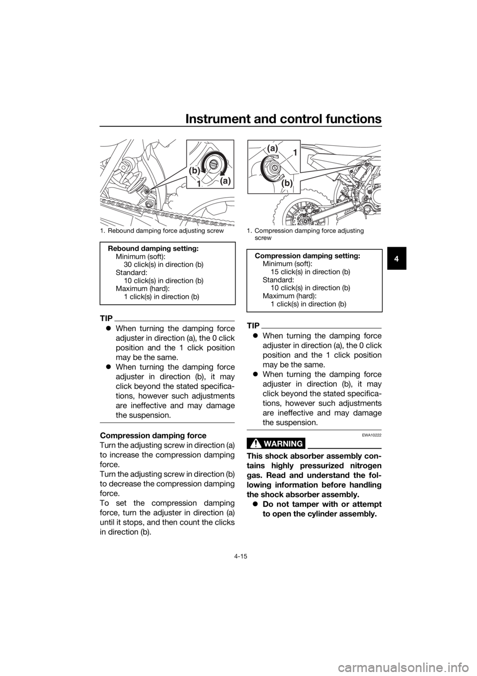
Re boun d d ampin g force
Turn the adjusting screw in direction (a)
to increase the rebound damping
force.
Turn the adjusting screw in direction (b)
to decrease the rebound damping
force.
To set the rebound damping force, turn
the adjuster in direction (a) until it
stops, and then count the clicks in di-
rection (b).
1. Distance A
Sprin g preloa d:
Minimum (soft): Distance A = 205.5 mm (8.09 in)
Standard: Distance A = 199.0 mm (7.83 in)
Maximum (hard):
Distance A = 195.0 mm (7.68 in)
Ti ghtenin g torque:
Locknut: 30 N·m (3.0 kgf·m, 22 lb·ft)
1
Tightening torque:
Rear frame bolt: 23 N·m (2.3 kgf·m, 17 lb·ft)
Ti ghtening torque:
Muffler bolt: 10 N·m (1.0 kgf·m, 7.4 lb·ft)
UBR882E0.book Page 14 Wednesday, February 26, 2020 11:39 AM
Page 41 of 92
Instrument and control functions
4-15
4
TIP
When turning the damping force
adjuster in direction (a), the 0 click
position and the 1 click position
may be the same.
When turning the damping force
adjuster in direction (b), it may
click beyond the stated specifica-
tions, however such adjustments
are ineffective and may damage
the suspension.
Compression dampin g force
Turn the adjusting screw in direction (a)
to increase the compression damping
force.
Turn the adjusting screw in direction (b)
to decrease the compression damping
force.
To set the compression damping
force, turn the adjuster in direction (a)
until it stops, and then count the clicks
in direction (b).
TIP
When turning the damping force
adjuster in direction (a), the 0 click
position and the 1 click position
may be the same.
When turning the damping force
adjuster in direction (b), it may
click beyond the stated specifica-
tions, however such adjustments
are ineffective and may damage
the suspension.
WARNING
EWA10222
This shock ab sorber assem bly con-
tains hig hly pressurize d nitro gen
g as. Rea d an d un derstan d the fol-
lowin g information before han dlin g
the shock a bsor ber assem bly.
Do not tamper with or attempt
to open the cylind er assembly.
1. Rebound damping force adjusting screw
Re boun d d ampin g settin g:
Minimum (soft): 30 click(s) in direction (b)
Standard: 10 click(s) in direction (b)
Maximum (hard):
1 click(s) in direction (b)
1(a)
(b)
1. Compression damping force adjusting
screw
Compression dampin g settin g:
Minimum (soft): 15 click(s) in direction (b)
Standard: 10 click(s) in direction (b)
Maximum (hard):
1 click(s) in direction (b)
(b)
(a)1
UBR882E0.book Page 15 Wednesday, February 26, 2020 11:39 AM
Page 45 of 92

For your safety – pre-operation checks
5-2
5
Drive chain• Check chain slack.
• Adjust if necessary.
• Check chain condition.
• Lubricate if necessary. 7-21,
7-22
Drive sprocket • Check the drive sprocket nut torque.
• Tighten if necessary.
—
Wheels an d tires •Check for damage.
• Check tire condition and tread depth.
• Check air pressure.
• Correct if necessary.
• Check for loose spokes and tighten if necessary. 7-14,
7-16
Shift ped al • Make sure that operation is smooth.
• Check the shift pedal bolt torque.
• Correct if necessary. 7-18
Brake ped al • Make sure that operation is smooth.
• Lubricate pedal pivoting point if necessary. 7-24
Brake an d clutch le-
vers • Make sure that operation is smooth.
• Lubricate lever pivoting points if necessary.
7-24
Steerin g • Check that the handlebar can be turned smoothly and
has no excessive play. 7-26
Front fork and rear
shock a bsor ber as-
sem bly • Check that they operate smoothly and there is no oil
leakage. 4-9,
4-11,
4-12, 7-26
Chassis fasteners • Make sure that all nuts, bolts and screws are properly
tightened.
• Check all cotter pins for damage and correct install- ment.
• Tighten or replace if necessary. —
Movin g parts an d ca-
b les • Check the control cables for damage.
• Check that the control cables move smoothly.
• Check that the control cables are not caught when the
handlebars are turned or when the front forks travel up
and down.
• Lubricate moving parts and cables if necessary. 7-23,
7-24,
7-25, 7-25
Exhaust system • Check that the exhaust pipe and muffler are tightly
mounted and have no cracks.
• Check for leakage. —
En gine stop switch • Check operation. 4-1
I g nition system • Check that all leads and cables are properly connected. 7-6
ITEM
CHECKSPAGE
UBR882E0.book Page 2 Wednesday, February 26, 2020 11:39 AM
Page 46 of 92
Operation and important rid ing points
6-1
6
EAU15952
Read the Owner’s Manual carefully to
become familiar with all controls. If
there is a control or function you do not
understand, ask your Yamaha dealer.
WARNING
EWA10272
Failure to familiarize yourself with
the controls can lead to loss of con-
trol, which coul d cause an acci dent
or injury.
EAU41506
En gine break-in
WARNING
EWA10322
Failure to properly maintain the vehi-
cle or performin g maintenance ac-
tivities incorrectly may increase
your risk of injury or death during
service or while usin g the vehicle. If
you are not familiar with vehicle ser-
vice, have a Yamaha d ealer perform
service.
TIP
Before starting the engine for the first
time, the air filter must be lubricated.
(See page 7-10.)
En gine break-in proced ure
1. Fill the fuel tank with a break-in oil- fuel mixture as follows.
2. Start and warm up the engine. Check the operation of the con-
trols and the engine stop switch.
(See page 4-1.)
3. Operate the motorcycle in the low- er gears at moderate throttle
openings for 5 to 8 minutes. Stop
the engine and check the spark
plug condition (see page 7-6); it
will show a rich condition during
break-in.
4. Allow the engine to cool. Restart the engine and operate the motor-
cycle as in the step above for 5
minutes. Then, very briefly shift to
Recommen ded 2-stroke en gine oil:
YA M A L U B E 2 R
Mixin g ratio ( gasoline to oil):
15:1
UBR882E0.book Page 1 Wednesd ay, February 26, 2020 11:39 AM