engine oil YAMAHA YZ85 2002 User Guide
[x] Cancel search | Manufacturer: YAMAHA, Model Year: 2002, Model line: YZ85, Model: YAMAHA YZ85 2002Pages: 504, PDF Size: 40.45 MB
Page 134 of 504

3 - 7
INSP
ADJ
RADIATOR CAP INSPECTION
CAUTION:
lDo not mix more than one type of ethyl-
ene glycol antifreeze containing corro-
sion inhibitors for aluminum engine.
lDo not use water containing impurities or
oil.
7. Install:
lRadiator cap
Start the engine and warm it up for a sev-
eral minutes.
8. Check:
lCoolant level
Coolant level low ® Add coolant. Handling notes of coolant:
The coolant is harmful so it should be han-
dled with special care.
WARNING
lWhen coolant splashes to your eye.
Thoroughly wash your eye with water
and see your doctor.
lWhen coolant splashes to your clothes.
Quickly wash it away with water and
then with soap.
lWhen coolant is swallowed.
Quickly make him vomit and take him
to a doctor.
EC355000
RADIATOR CAP INSPECTION
1. Inspect:
lSeal (radiator cap) 1
lValve and valve seat 2
Crack/damage ® Replace.
Exist fur deposits 3 ® Clean or replace.
5PA30050
Page 142 of 504
3 - 11
INSP
ADJ
AIR FILTER CLEANING
AIR FILTER CLEANING
NOTE:
Proper air filter maintenance is the biggest key
to preventing premature engine wear and
damage.
CAUTION:
Never run the engine without the air filter
element in place; this would allow dirt and
dust to enter the engine and cause rapid
wear and possible engine damage.
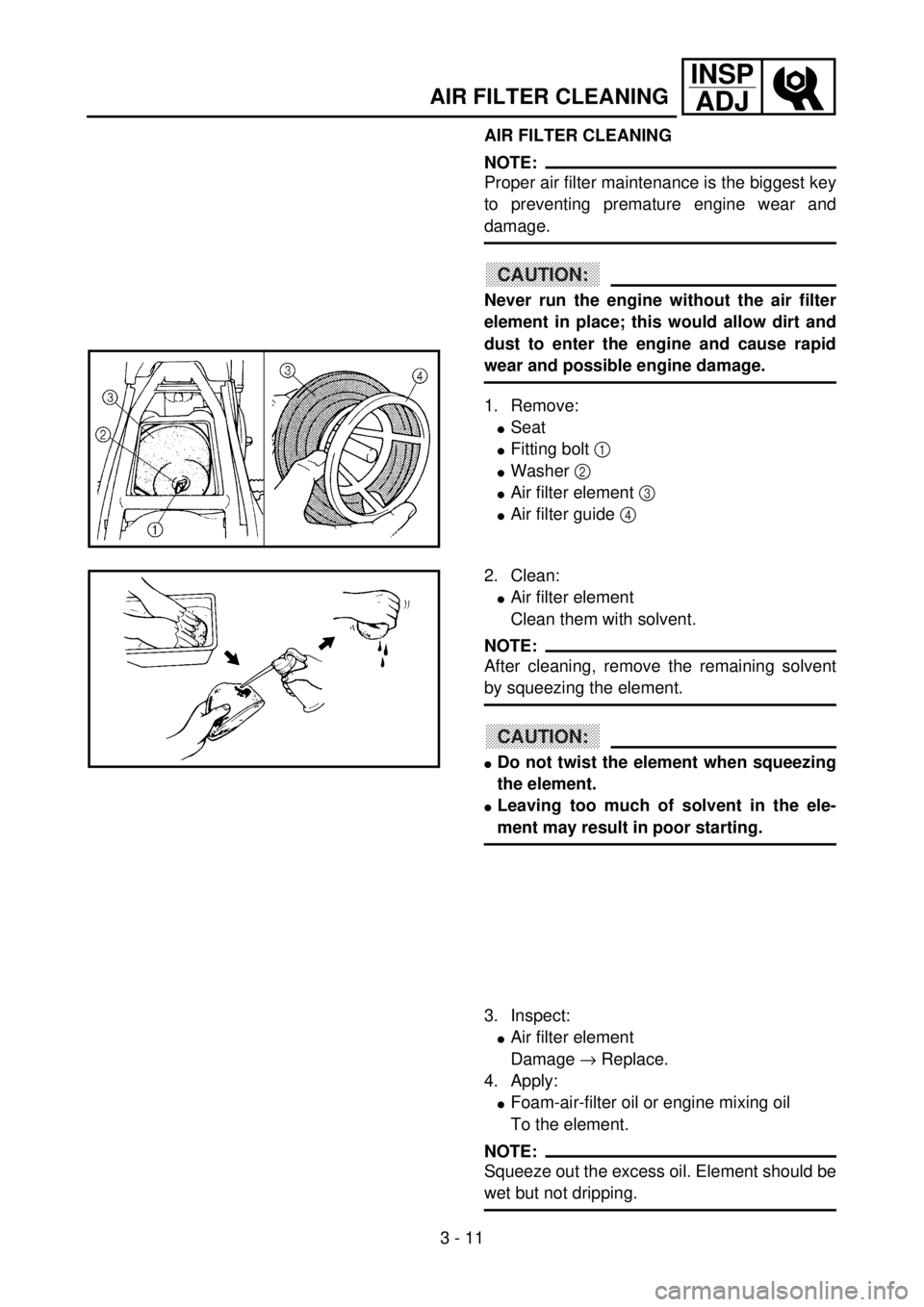
1. Remove:
lSeat
lFitting bolt 1
lWasher 2
lAir filter element 3
lAir filter guide 4
5PA30150
2. Clean:
lAir filter element
Clean them with solvent.
NOTE:
After cleaning, remove the remaining solvent
by squeezing the element.
CAUTION:
lDo not twist the element when squeezing
the element.
lLeaving too much of solvent in the ele-
ment may result in poor starting.
5PA30160
3. Inspect:
lAir filter element
Damage ® Replace.
4. Apply:
lFoam-air-filter oil or engine mixing oil
To the element.
NOTE:
Squeeze out the excess oil. Element should be
wet but not dripping.
Page 144 of 504
3 - 12
INSP
ADJ
TRANSMISSION OIL REPLACEMENT
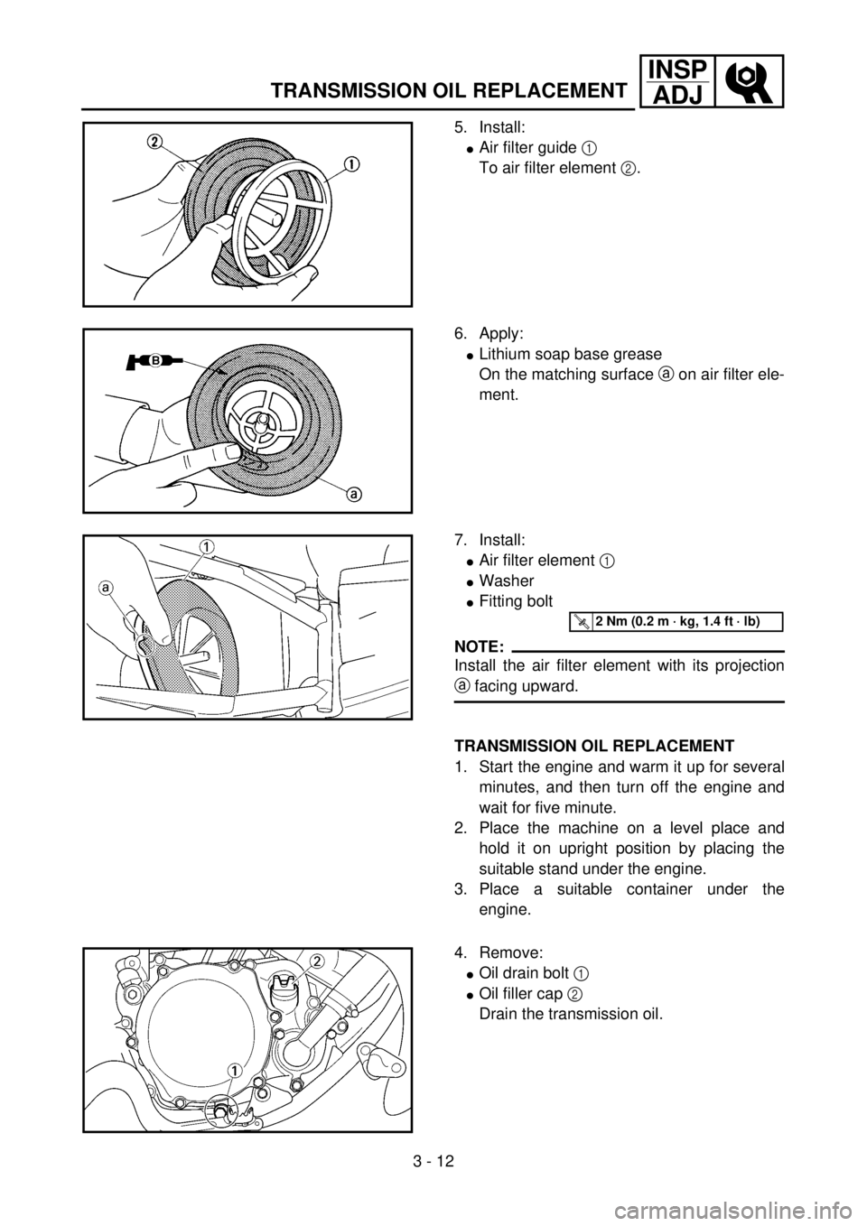
5. Install:
lAir filter guide 1
To air filter element 2.
5PA30170
6. Apply:
lLithium soap base grease
On the matching surface a on air filter ele-
ment.
5PA30180
7. Install:
lAir filter element 1
lWasher
lFitting bolt
NOTE:
Install the air filter element with its projection
a facing upward.
5PA30190
T R..2 Nm (0.2 m · kg, 1.4 ft · lb)
TRANSMISSION OIL REPLACEMENT
1. Start the engine and warm it up for several
minutes, and then turn off the engine and
wait for five minute.
2. Place the machine on a level place and
hold it on upright position by placing the
suitable stand under the engine.
3. Place a suitable container under the
engine.
4. Remove:
lOil drain bolt 1
lOil filler cap 2
Drain the transmission oil.
5PA30200
Page 166 of 504
3 - 23
INSP
ADJ
DRIVE CHAIN SLACK ADJUSTMENT
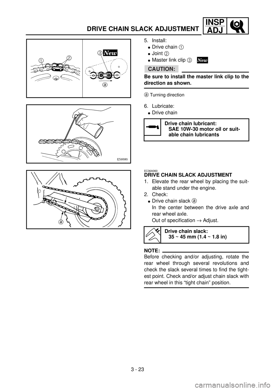
5. Install:
lDrive chain 1
lJoint 2
lMaster link clip 3
CAUTION:
Be sure to install the master link clip to the
direction as shown.
aTurning direction5PA30530
6. Lubricate:
lDrive chain
Drive chain lubricant:
SAE 10W-30 motor oil or suit-
able chain lubricants
5PA30540
EC36A060
DRIVE CHAIN SLACK ADJUSTMENT
1. Elevate the rear wheel by placing the suit-
able stand under the engine.
2. Check:
lDrive chain slack
a
In the center between the drive axle and
rear wheel axle.
Out of specification ® Adjust.
NOTE:
Before checking and/or adjusting, rotate the
rear wheel through several revolutions and
check the slack several times to find the tight-
est point. Check and/or adjust chain slack with
rear wheel in this “tight chain” position.
Drive chain slack:
35 ~ 45 mm (1.4 ~ 1.8 in)
5PA30550
Page 168 of 504

3 - 24
INSP
ADJFRONT FORK INSPECTION/
FRONT FORK OIL SEAL AND DUST SEAL CLEANING
3. Adjust:
lDrive chain slack
Drive chain slack adjustment steps:
lLoosen the axle nut 1 and locknuts 2.
lAdjust chain slack by turning the adjusters 3.
To tighten
® Turn adjuster
3 clockwise.
To loosen
® Turn adjuster
3 counter-
clockwise and push wheel forward.
lTurn each adjuster exactly the same
amount to maintain correct axle alignment.
(There are marks a on each side of chain
puller alignment.)
NOTE:
Turn the adjuster so that the chain is in line
with the sprocket, as viewed from the rear.
CAUTION:
Too small chain slack will overload the
engine and other vital parts; keep the
slack within the specified limits.
lTighten the axle nut while pushing down
the drive chain.
T R..
Axle nut:
110 Nm (11.0 m • kg, 80 ft • lb)
lTighten the locknuts.
5PA30560
EC36C000
FRONT FORK INSPECTION
1. Inspect:
lFront fork smooth action
Operate the front brake and stroke the front
fork.
Unsmooth action/oil leakage ® Repair or
replace.
5PA30570
EC36D001
FRONT FORK OIL SEAL AND DUST SEAL
CLEANING
1. Remove:
lProtector 1
lDust seal 2
NOTE:
Use a thin screw driver, and be careful not to
damage the inner fork tube and dust seal.5PA30580
Page 170 of 504
3 - 25
INSP
ADJFRONT FORK INTERNAL PRESSURE BLEEDING/FRONT
FORK REBOUND DAMPING FORCE ADJUSTMENT
2. Clean:
lDust seal a
lOil seal b
NOTE:
lClean the dust seal and oil seal after every
run.
lApply the lithium soap base grease on the
inner tube.
5PA30590
FRONT FORK INTERNAL PRESSURE
BLEEDING
NOTE:
If the front fork initial movement feels stiff dur-
ing a run, bleed the front fork internal pressure.
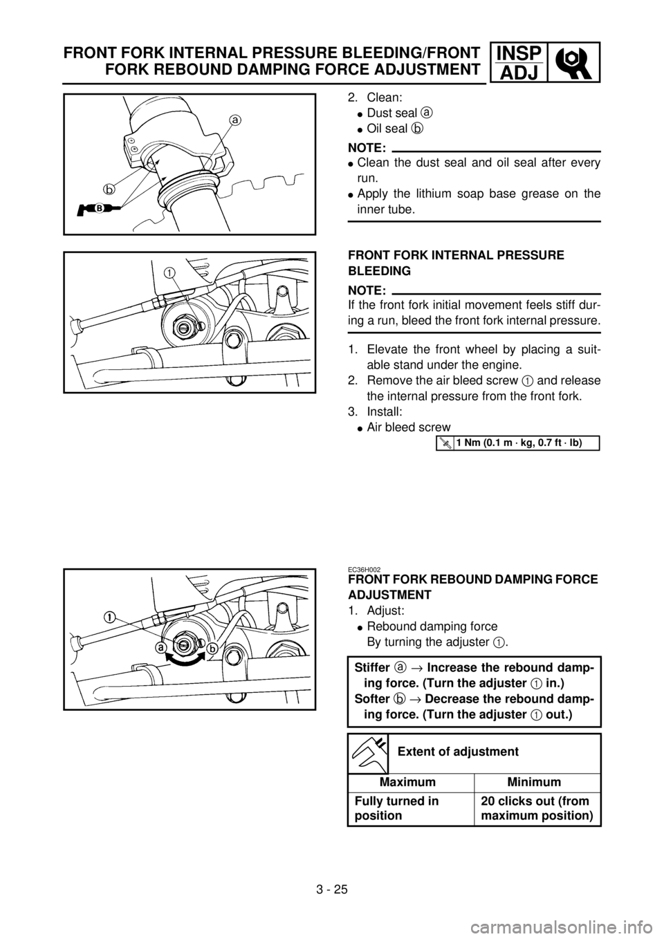
1. Elevate the front wheel by placing a suit-
able stand under the engine.
2. Remove the air bleed screw 1 and release
the internal pressure from the front fork.
3. Install:
lAir bleed screw
5PA30590
T R..1 Nm (0.1 m · kg, 0.7 ft · lb)
EC36H002
FRONT FORK REBOUND DAMPING FORCE
ADJUSTMENT
1. Adjust:
lRebound damping force
By turning the adjuster 1.
Stiffer
a
® Increase the rebound damp-
ing force. (Turn the adjuster
1 in.)
Softer
b
® Decrease the rebound damp-
ing force. (Turn the adjuster
1 out.)
Extent of adjustment
Maximum Minimum
Fully turned in
position20 clicks out (from
maximum position)
5PA30600
Page 240 of 504
4 - 23
ENG
NOTE:
When you purchase a cylinder, you cannot
designate its size. Choose the piston that
matches the above chart.
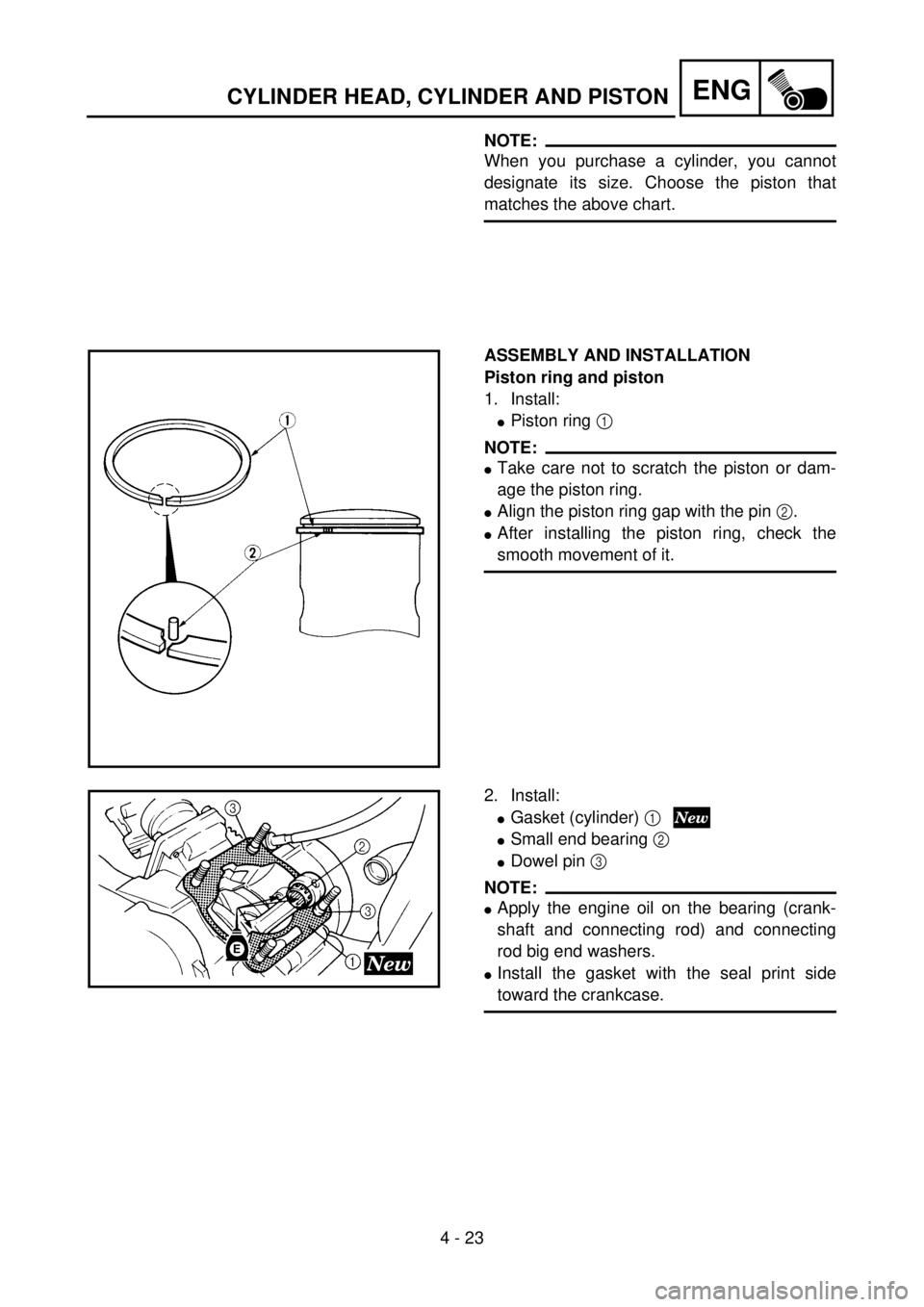
ASSEMBLY AND INSTALLATION
Piston ring and piston
1. Install:
lPiston ring 1
NOTE:
lTake care not to scratch the piston or dam-
age the piston ring.
lAlign the piston ring gap with the pin 2.
lAfter installing the piston ring, check the
smooth movement of it.
5PA40620
2. Install:
lGasket (cylinder) 1
lSmall end bearing 2
lDowel pin 3
NOTE:
lApply the engine oil on the bearing (crank-
shaft and connecting rod) and connecting
rod big end washers.
lInstall the gasket with the seal print side
toward the crankcase.
5PA40630
CYLINDER HEAD, CYLINDER AND PISTON
Page 242 of 504
4 - 24
ENG
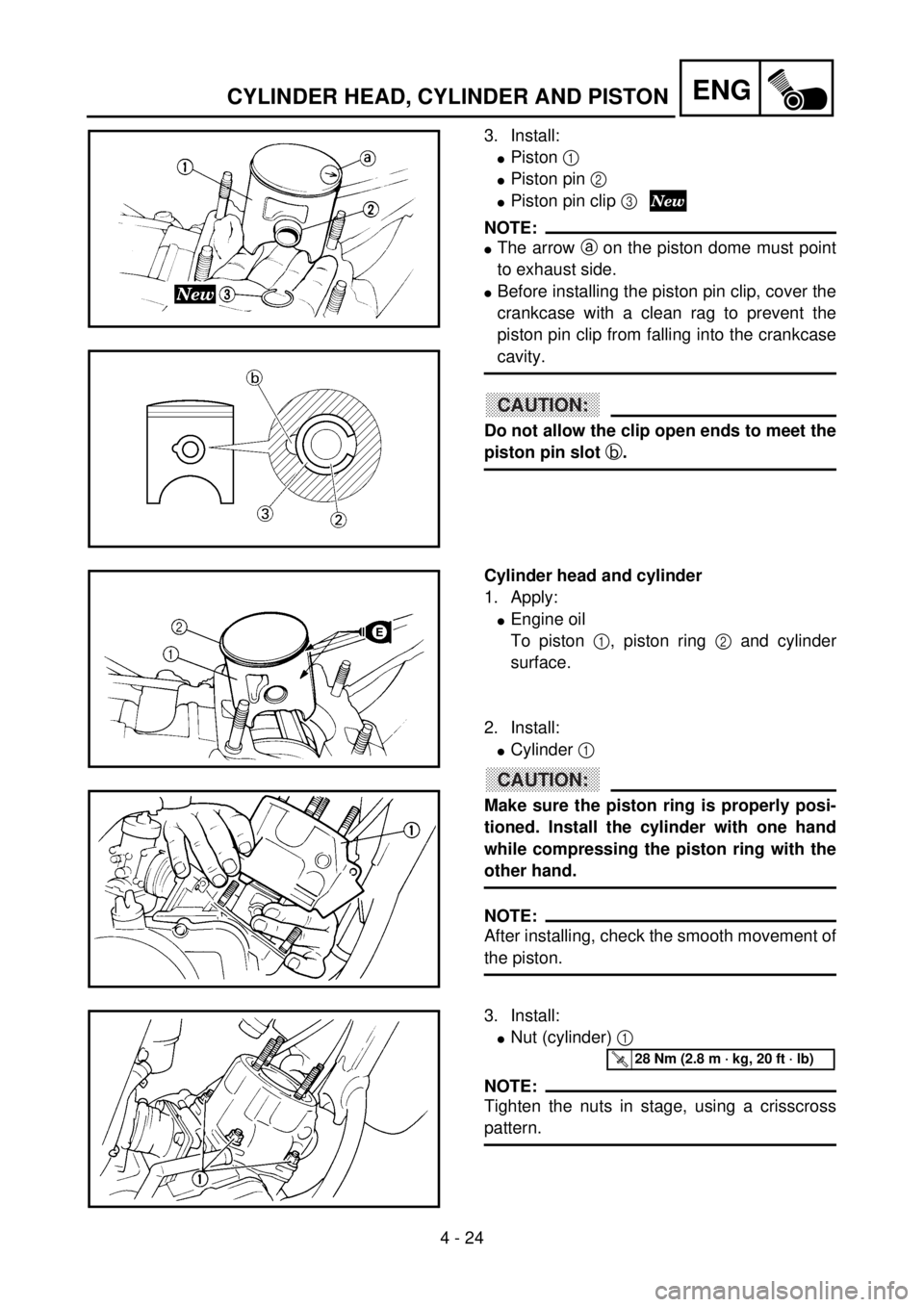
3. Install:
lPiston 1
lPiston pin 2
lPiston pin clip 3
NOTE:
lThe arrow a on the piston dome must point
to exhaust side.
lBefore installing the piston pin clip, cover the
crankcase with a clean rag to prevent the
piston pin clip from falling into the crankcase
cavity.
CAUTION:
Do not allow the clip open ends to meet the
piston pin slot b.
5PA40640
5PA40650
Cylinder head and cylinder
1. Apply:
lEngine oil
To piston 1, piston ring 2 and cylinder
surface.
2. Install:
lCylinder 1
CAUTION:
Make sure the piston ring is properly posi-
tioned. Install the cylinder with one hand
while compressing the piston ring with the
other hand.
NOTE:
After installing, check the smooth movement of
the piston.
5PA40660
5PA40670
3. Install:
lNut (cylinder) 1
NOTE:
Tighten the nuts in stage, using a crisscross
pattern.
5PA40680
T R..28 Nm (2.8 m · kg, 20 ft · lb)
CYLINDER HEAD, CYLINDER AND PISTON
Page 246 of 504

4 - 26
ENGCLUTCH AND PRIMARY DRIVEN GEAR
EC490000
CLUTCH AND PRIMARY DRIVEN GEAR
EC498000
CLUTCH PLATE AND FRICTION PLATE
5PA40720
Extent of removal:
1 Clutch plate and friction plate removal
Extent of removal Order Part name Q’ty Remarks
CLUTCH PLATE AND FRIC-
TION PLATE REMOVAL
Preparation for removal Drain the transmission oil. Refer to “TRANSMISSION OIL
REPLACEMENT” section in the CHAP-
TER 3.
Clutch cable Disconnect at engine side.
1 Clutch cover 1
2 Bolt (clutch spring) 5
3 Clutch spring 5
4 Pressure plate 1
5 Friction plate 7
6 Clutch plate 6
1
Page 270 of 504

4 - 38
ENG
2. Install:
lSpring guide 1
NOTE:
Slide the spring guide into the kick shaft, make
sure the groove a in the spring guide fits on
the stopper of the torsion spring.
5PA41120
3. Install:
lKick shaft assembly 1
NOTE:
lApply the transmission oil on the kick shaft.
lApply the lithium soap base grease on the
kick shaft stopper.
lSlide the kick shaft assembly into the crank-
case, make sure the clip 2 and kick shaft
stopper a fit into their home positions b, c.5PA41130
4. Hook:
lTorsion spring 1
NOTE:
Turn the torsion spring clockwise and hook
into the proper hole a in the crankcase.
5PA41140
Kick idle gear
1. Install:
lWasher 1
lKick idle gear 2
lCirclip 3
NOTE:
lApply the transmission oil on the kick idle
gear inner circumference.
lInstall the kick idle gear with its groove a
facing the engine.
5PA41150
KICK SHAFT, SHIFT SHAFT AND PRIMARY DRIVE GEAR