bolt pattern YAMAHA YZ85 2002 Owners Manual
[x] Cancel search | Manufacturer: YAMAHA, Model Year: 2002, Model line: YZ85, Model: YAMAHA YZ85 2002Pages: 504, PDF Size: 40.45 MB
Page 258 of 504

4 - 32
ENG
7. Install:
lPressure plate 1
NOTE:
Align the punch mark a on the pressure plate
with the punch mark b on the clutch boss.
5PA40920
8. Install:
lClutch spring 1
lBolt (clutch spring) 2
NOTE:
Tighten the bolts (clutch spring) in stage, using
a crisscross pattern.
5PA40930
T R..6 Nm (0.6 m · kg, 4.3 ft · lb)
9. Install:
lDowel pin 1
lGasket (clutch cover) 2
5PA40940
10. Install:
lClutch cover 1
lBolt (clutch cover) 2
NOTE:
Tighten the bolts in stage, using a crisscross
pattern.
5PA40950
T R..10 Nm (1.0 m · kg, 7.2 ft · lb)
CLUTCH AND PRIMARY DRIVEN GEAR
Page 274 of 504

4 - 40
ENG
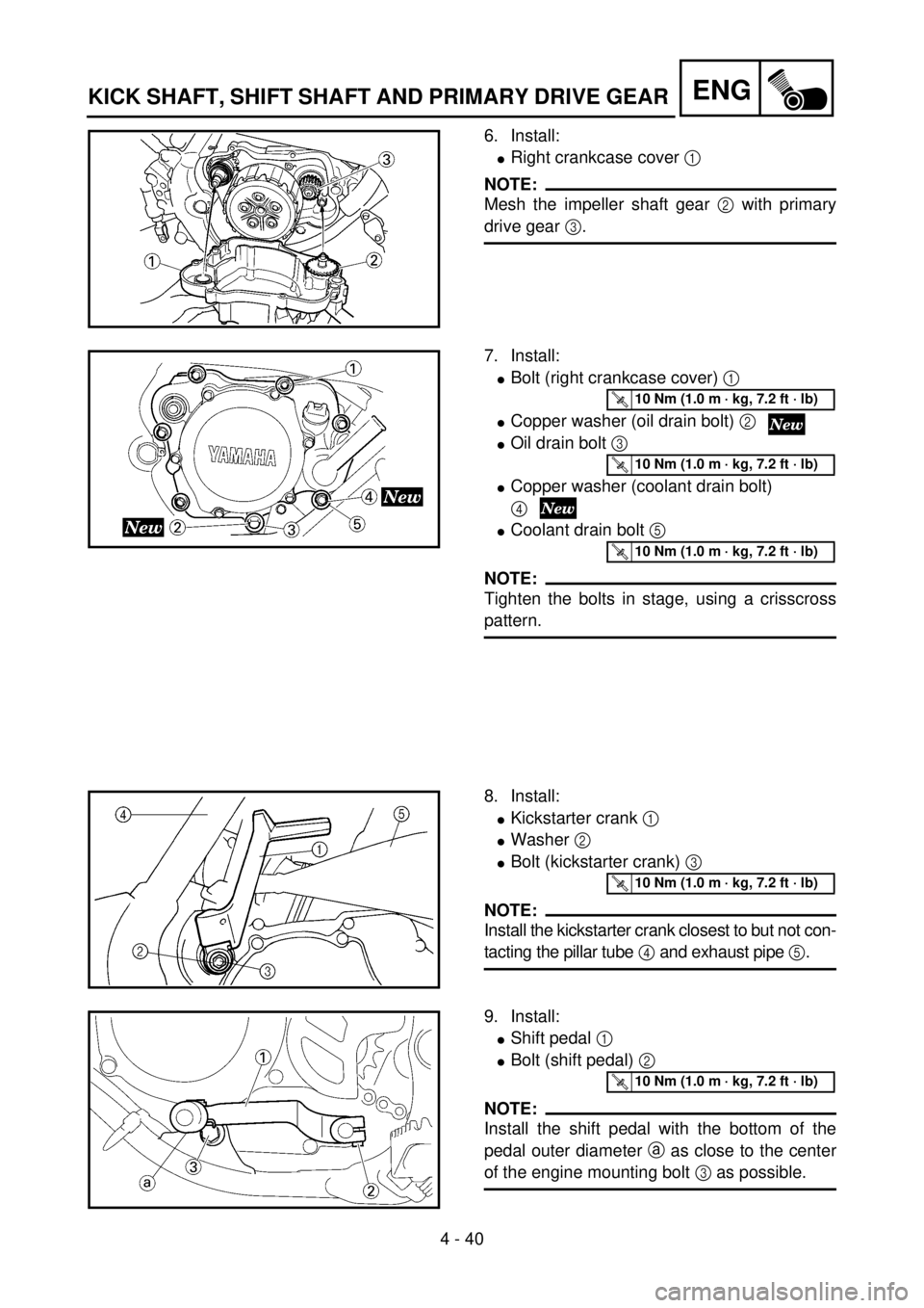
6. Install:
lRight crankcase cover 1
NOTE:
Mesh the impeller shaft gear 2 with primary
drive gear 3.
5PA41200
7. Install:
lBolt (right crankcase cover) 1
lCopper washer (oil drain bolt) 2
lOil drain bolt 3
lCopper washer (coolant drain bolt)
4
lCoolant drain bolt 5
NOTE:
Tighten the bolts in stage, using a crisscross
pattern.
5PA41210
T R..10 Nm (1.0 m · kg, 7.2 ft · lb)
T R..10 Nm (1.0 m · kg, 7.2 ft · lb)
T R..10 Nm (1.0 m · kg, 7.2 ft · lb)
8. Install:
lKickstarter crank 1
lWasher 2
lBolt (kickstarter crank) 3
NOTE:
Install the kickstarter crank closest to but not con-
tacting the pillar tube 4 and exhaust pipe 5.
5PA41220
T R..10 Nm (1.0 m · kg, 7.2 ft · lb)
9. Install:
lShift pedal 1
lBolt (shift pedal) 2
NOTE:
Install the shift pedal with the bottom of the
pedal outer diameter a as close to the center
of the engine mounting bolt 3 as possible.
5PA41230
T R..10 Nm (1.0 m · kg, 7.2 ft · lb)
KICK SHAFT, SHIFT SHAFT AND PRIMARY DRIVE GEAR
Page 298 of 504

4 - 52
ENG
EC4M5000
ASSEMBLY AND INSTALLATION
Engine installation
1. Install:
lEngine 1
Install the engine from right side.
lPivot shaft 2
lEngine mounting bolt (front) 3
lEngine mounting bolt (lower) 4
NOTE:
Apply the molybdenum disulfide grease on the
pivot shaft.
5PA41550
T R..63 Nm (6.3 m · kg, 45 ft · lb)
T R..69 Nm (6.9 m · kg, 50 ft · lb)
T R..69 Nm (6.9 m · kg, 50 ft · lb)
Drive sprocket
1. Install:
lDrive sprocket 1
lDrive chain 2
NOTE:
Install the drive sprocket together with the
drive chain.
5PA41560
2. Install:
lLock washer 1
lNut (drive sprocket) 2
NOTE:
Tighten the nut while applying the rear brake.
3. Bend the lock washer tab to lock the nut.
5PA41570
T R..60 Nm (6.0 m · kg, 43 ft · lb)
4. Install:
lGasket (left crankcase cover)
lLeft crankcase cover 1
lScrew (left crankcase cover) 2
NOTE:
Tighten the screws in stage, using a crisscross
pattern.
5PA41580
T R..5 Nm (0.5 m · kg, 3.6 ft · lb)
ENGINE REMOVAL
Page 336 of 504

5 - 7
CHAS
2. Install:
lBrake disc 1
lBolt (brake disc) 2
NOTE:
Tighten the bolts (brake disc) in stage, using a
crisscross pattern.
5PA50160
T R..12 Nm (1.2 m · kg, 8.7 ft · lb)
3. Install:
lRear wheel sprocket 1
lBolt (rear wheel sprocket) 2
lWasher (rear wheel sprocket) 3
lNut (rear wheel sprocket) 4
NOTE:
Tighten the nuts (rear wheel sprocket) in
stage, using a crisscross pattern.5PA50170
T R..42 Nm (4.2 m · kg, 30 ft · lb)
4. Install:
lCollar 1
NOTE:
Apply the lithium soap base grease on the oil
seal lip.
5PA50180
5. Install:
lWheel
NOTE:
Install the brake disc 1 between the brake
pads 2 correctly.
5PA50190
6. Install:
lDrive chain 1
NOTE:
Push the wheel 2 forward and install the drive
chain.
5PA50200
FRONT WHEEL AND REAR WHEEL