service YAMAHA YZ85 2014 Owners Manual
[x] Cancel search | Manufacturer: YAMAHA, Model Year: 2014, Model line: YZ85, Model: YAMAHA YZ85 2014Pages: 88, PDF Size: 1.8 MB
Page 6 of 88

INTRODUCTIONAN IMPORTANT NOTE TO PARENTS:
This motorcycle is not a toy. Before you let your child ride this motorcycle, you should understand the instructions and warn-
ings in this Owner’s Manual. Then be sure your child understands and will follow them. Children differ in skills, physical abil-
ities, and judgment. Some children may not be able to operate a motorcycle safely. Parents should supervise their child’s
use of the motorcycle at all times. Parents should permit continued use only if they determine that the child has the ability
to operate the motorcycle safely.
Motorcycles are sin gle track vehicles. Their safe use an d operation are d ependent upon the use of proper ri din g
techniques as well as the expertise of the operator. Every operator shoul d know the followin g requirements b efore
ri din g this motorcycle.
He or she should: Obtain thorough instructions from a competent source on all aspects of motorcycle operation.
Observe the warnings and maintenance requirements in this Owner’s Manual.
Obtain qualified training in safe and proper riding techniques.
Obtain professional technical service as indicated in this Owner’s Manual and/or when made necessary by mechanical
conditions.U1SN82E0.book Page 2 Friday, June 7, 2013 3:51 PM
Page 37 of 88
INSTRUMENT AND CONTROL FUNCTIONS
4-11
4
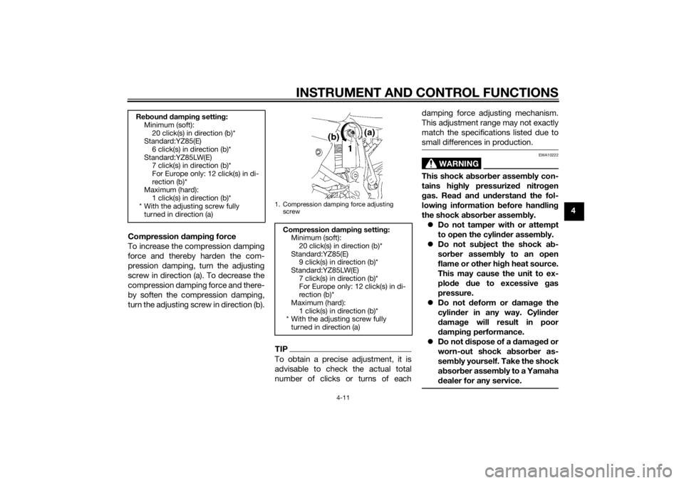
Compression dampin g force
To increase the compression damping
force and thereby harden the com-
pression damping, turn the adjusting
screw in direction (a). To decrease the
compression damping force and there-
by soften the compression damping,
turn the adjusting screw in direction (b).
TIPTo obtain a precise adjustment, it is
advisable to check the actual total
number of clicks or turns of each damping force adjusting mechanism.
This adjustment range may not exactly
match the specifications listed due to
small differences in production.
WARNING
EWA10222
This shock a
bsor ber assem bly con-
tains hig hly pressurize d nitro gen
g as. Rea d an d un derstan d the fol-
lowin g information before han dlin g
the shock a bsor ber assem bly.
Do not tamper with or attempt
to open the cylind er assembly.
Do not su bject the shock a b-
sor ber assem bly to an open
flame or other hi gh heat source.
This may cause the unit to ex-
plo de due to excessive gas
pressure.
Do not deform or damag e the
cylin der in any way. Cylin der
d ama ge will result in poor
d ampin g performance.
Do not dispose of a damag ed or
worn-out shock a bsor ber as-
sem bly
yourself. Take the shock
a b sor ber assem bly to a Yamaha
d ealer for any service.
Re boun d d ampin g settin g:
Minimum (soft):
20 click(s) in direction (b)*
Standard:YZ85(E)
6 click(s) in direction (b)*
Standard:YZ85LW(E) 7 click(s) in direction (b)*
For Europe only: 12 click(s) in di-
rection (b)*
Maximum (hard):
1 click(s) in direction (b)*
* With the adjusting screw fully turned in direction (a)
1. Compression damping force adjusting
screw
Compression dampin g setting :
Minimum (soft): 20 click(s) in direction (b)*
Standard:YZ85(E) 9 click(s) in direction (b)*
Standard:YZ85LW(E)
7 click(s) in direction (b)*
For Europe only: 12 click(s) in di-
rection (b)*
Maximum (hard): 1 click(s) in direction (b)*
* With the adjusting screw fully
turned in direction (a)
U1SN82E0.book Page 11 Friday, June 7, 2013 3:51 PM
Page 44 of 88
OPERATION AND IMPORTANT RIDING POINTS
6-3
6
EAU41504
Engine break-in
WARNING
EWA10322
Failure to properly maintain the vehi-
cle or performin g maintenance ac-
tivities incorrectly may increase
your risk of injury or death durin g
service or while usin g the vehicle. If
you are not familiar with vehicle ser-
vice, have a Yamaha d ealer perform
service.1. Before starting the engine, fill the fuel tank with a break-in oil-fuel
mixture as follows.
2. Start and warm up the engine. Check the operation of the con-
trols and the engine stop button.
(See page 4-1.)
3. Operate the motorcycle in the lower gears at moderate throttle
openings for five to eight minutes.
Stop the engine and check the spark plug condition (see page
7-8); it will show a rich condition
during break-in.
4. Allow the engine to cool. Restart the engine and operate the motor-
cycle as in the step above for five
minutes. Then, very briefly shift to
the higher gears and check the
full-throttle response. Stop the en-
gine and check the spark plug.
5. After again allowing the engine to cool, restart and run the motorcy-
cle for five more minutes. Full
throttle and the higher gears may
be used, but sustained full-throttle
operation should be avoided.
Stop the engine and check the
spark plug again.
6. Allow the engine to cool, remove the cylinder head and cylinder,
and inspect the piston and cylin-
der. Remove any high spots on
the piston with #600-grit wet
sandpaper. Clean all components
and carefully reassemble the cyl-
inder head and cylinder.
7. Drain the break-in oil-fuel mixture from the fuel tank and refill with
the specified mix. (See page 4-3.) 8. Start the engine and check the op-
eration of the motorcycle through-
out its entire operating range.
Stop the engine and check the
spark plug condition. Restart the
motorcycle and ride it for about 10
to 15 more minutes. The motorcy-
cle will now be ready to ride nor-
mally.
After the engine break-in period, thor-
oughly check the motorcycle for loose
parts, oil leakage and any other prob-
lems. Be sure to inspect and make ad-
justments thoroughly, especially cable
and drive chain slack and loose
spokes. In addition, check all fittings
and fasteners for looseness, and tight-
en if necessary.
NOTICE
ECA15561
When any of the followin g parts
have been replaced , they must
b e broken in.
Cylin der or crankshaft:
A bout one hour of b reak-in op-
eration is necessary.
Piston, rin gs or transmission
g ears:
Recommen ded 2-stroke en gine oil:
See page 9-1.
Mixin g ratio ( gasoline to oil):
15:1
U1SN82E0.book Page 3 Friday, June 7, 2013 3:51 PM
Page 46 of 88
PERIODIC MAINTENANCE AND ADJUSTMENT
7-1
7
EAU42074
Periodic inspection, adjustment, and
lubrication will keep your vehicle in the
safest and most efficient condition
possible. Safety is an obligation of the
vehicle owner/operator. The most im-
portant points of vehicle inspection,
adjustment, and lubrication are ex-
plained on the following pages.
The intervals given in the periodic
maintenance and lubrication chart
should be simply considered as a gen-
eral guide under normal riding condi-
tions. However, depending on the
weather, terrain, geographical location,
and individual use, the maintenance in-
tervals may need to be shortened.
WARNING
EWA10322
Failure to properly maintain the vehi-
cle or performing maintenance ac-
tivities incorrectly may increase
your risk of injury or death durin g
service or while usin g the vehicle. If
you are not familiar with vehicle ser-
vice, have a Yamaha d ealer perform
service.
WARNING
EWA15123
Turn off the en gine when performin g
maintenance unless otherwise
specified .
A runnin g en gine has movin g
parts that can catch on body
parts or clothin g an d electrical
parts that can cause shocks or
fires.
Runnin g the en gine while ser-
vicin g can lead to eye injury,
b urns, fire, or car bon monoxi de
poisonin g – possi bly lea din g to
d eath. See pag e 2-2 for more in-
formation a bout car bon monox-
i d e.
WARNING
EWA15461
Brake discs, calipers, drums, and
linin gs can b ecome very hot d uring
use. To avoi d possi ble burns, let
b rake components cool before
touchin g them.
U1SN82E0.book Page 1 Friday, June 7, 2013 3:51 PM
Page 51 of 88
PERIODIC MAINTENANCE AND ADJUSTMENT
7-6
7
EAU42012
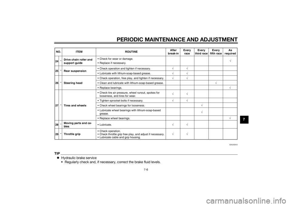
TIPHydraulic brake service
• Regularly check and, if necessary, correct the brake fluid levels.
√
√√
√
24
*Drive chain roller and
support guide
Replace if necessary. Check for wear or damage.
√
25 *Rear suspension Check operation and tighten if necessary.
Lubricate with
lithium-soap-based grease
.
NO.
ITEM ROUTINEAfter
break-in Every
race Every
third race Every
fifth race As
required
√ √√
√
√ √
√
√ √
√
√
√ √
√
√
26
*Steering head Check operation, free play, and tighten if necessary.
Clean and lubricate with lithium-soap-based grease.
Replace bearings.
27 *Tires and wheels Check tire air pressure, wheel runout, spokes for
looseness, and tires for wear.
Tighten sprocket bolts if necessary.
Check wheel bearings for looseness.
Lubricate wheel bearings with lithium-soap-based grease.
Replace wheel bearings.
28 *Moving parts and ca-
bles Lubricate.
29 *Throttle grip Check operation.
Check throttle grip free play, and adjust if necessary.
Lubricate cable and grip housing.
U1SN82E0.book Page 6 Friday, June 7, 2013 3:51 PM
Page 59 of 88
PERIODIC MAINTENANCE AND ADJUSTMENT
7-14
7
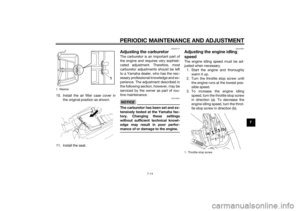
10. Install the air filter case cover in
the original position as shown.
11. Install the seat.
EAU42111
A djustin g the car buretorThe carburetor is an important part of
the engine and requires very sophisti-
cated adjustment. Therefore, most
carburetor adjustments should be left
to a Yamaha dealer, who has the nec-
essary professional knowledge and ex-
perience. The adjustment described in
the following section, however, may be
serviced by the owner as part of rou-
tine maintenance.NOTICE
ECA10551
The car buretor has b een set and ex-
tensively teste d at the Yamaha fac-
tory. Chan gin g these settin gs
without sufficient technical knowl-
e dge may result in poor perfor-
mance of or damag e to the en gine.
EAU44391
A djustin g the en gine i dlin g
spee dThe engine idling speed must be ad-
justed when necessary.
1. Start the engine and thoroughly warm it up.
2. Turn the throttle stop screw until the engine runs at the lowest pos-
sible speed.
3. To increase the engine idling speed, turn the throttle stop screw
in direction (a). To decrease the
engine idling speed, turn the throt-
tle stop screw in direction (b).
1. Washer
1
1. Throttle stop screw
U1SN82E0.book Page 14 Friday, June 7, 2013 3:51 PM
Page 68 of 88
PERIODIC MAINTENANCE AND ADJUSTMENT
7-23
7loa
d the en gine as well as other
vital parts of the motorcycle an d
can lead to chain slippa ge or
b reakag e. To prevent this from
occurrin g, keep the drive chain
slack within the specifie d limits.
[ECA10572]
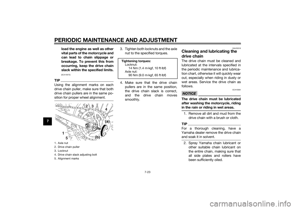
TIPUsing the alignment marks on each
drive chain puller, make sure that both
drive chain pullers are in the same po-
sition for proper wheel alignment.
3. Tighten both locknuts and the axle
nut to the specified torques.
4. Make sure that the drive chain pullers are in the same position,
the drive chain slack is correct,
and the drive chain moves
smoothly.
EAU23018
Cleanin g an d lu bricatin g the
d rive chainThe drive chain must be cleaned and
lubricated at the intervals specified in
the periodic maintenance and lubrica-
tion chart, otherwise it will quickly wear
out, especially when riding in dusty or
wet areas. Service the drive chain as
follows.NOTICE
ECA10584
The drive chain must be lu bricated
after washin g the motorcycle, ri din g
in the rain or ri din g in wet areas.1. Remove all dirt and mud from the
drive chain with a brush or cloth.TIPFor a thorough cleaning, have a
Yamaha dealer remove the drive chain and soak it in solvent.2. Spray Yamaha chain lubricant or other suitable chain lubricant on
the entire chain, making sure that
all side plates and rollers have
been sufficiently oiled.
1. Axle nut
2. Drive chain puller
3. Locknut
4. Drive chain slack adjusting bolt
5. Alignment marks
5 4
32
Ti
ghtenin g torques:
Locknut: 14 Nm (1.4 m·kgf, 10 ft·lbf)
Axle nut:
90 Nm (9.0 m·kgf, 65 ft·lbf)
U1SN82E0.book Page 23 Friday, June 7, 2013 3:51 PM
Page 73 of 88
PERIODIC MAINTENANCE AND ADJUSTMENT
7-28
7
EAU24351
Supporting the motorcycleSince this model is not equipped with a
centerstand, follow these precautions
when removing the front and rear
wheel or performing other mainte-
nance requiring the motorcycle to
stand upright. Check that the motorcy-
cle is in a stable and level position be-
fore starting any maintenance. A
strong wooden box can be placed un-
der the engine for added stability.
To service the front wheel
1. Stabilize the rear of the motorcy- cle by using a motorcycle stand
or, if an additional motorcycle
stand is not available, by placing a
jack under the frame in front of the
rear wheel.
2. Raise the front wheel off the ground by using a motorcycle
stand.
To service the rear wheel
Raise the rear wheel off the ground by
using a motorcycle stand or, if a motor-
cycle stand is not available, by placing a jack either under each side of the
frame in front of the rear wheel or under
each side of the swingarm.
EAU24361
Front wheel
EAU56371
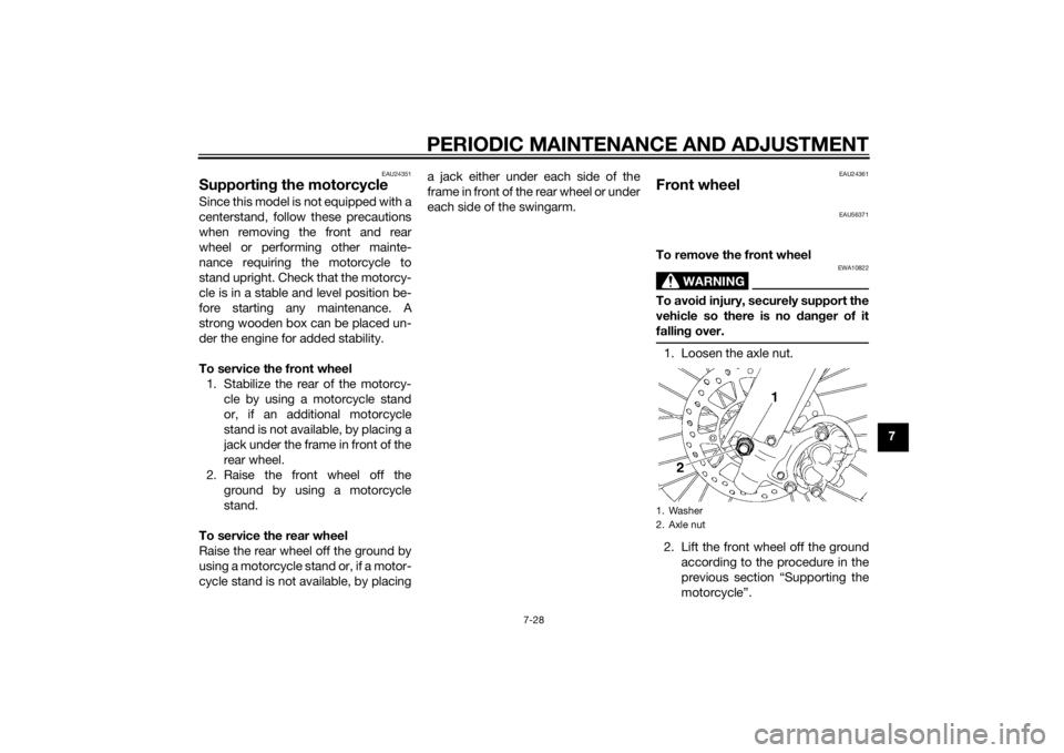
To remove the front wheel
WARNING
EWA10822
To avoi
d injury, securely support the
vehicle so there is no dan ger of it
fallin g over.1. Loosen the axle nut.
2. Lift the front wheel off the ground
according to the procedure in the
previous section “Supporting the
motorcycle”.1. Washer
2. Axle nut
U1SN82E0.book Page 28 Friday, June 7, 2013 3:51 PM
Page 76 of 88

PERIODIC MAINTENANCE AND ADJUSTMENT
7-31
75. Adjust the drive chain slack. (See
page 7-22.)
6. Tighten the locknuts and the axle nut to their specified torques.
EAU25872
Trou bleshootin gAlthough Yamaha motorcycles receive
a thorough inspection before shipment
from the factory, trouble may occur
during operation. Any problem in the
fuel, compression, or ignition systems,
for example, can cause poor starting
and loss of power.
The following troubleshooting charts
represent quick and easy procedures
for checking these vital systems your-
self. However, should your motorcycle
require any repair, take it to a Yamaha
dealer, whose skilled technicians have
the necessary tools, experience, and
know-how to service the motorcycle
properly.
Use only genuine Yamaha replace-
ment parts. Imitation parts may look
like Yamaha parts, but they are often
inferior, have a shorter service life and
can lead to expensive repair bills.
WARNING
EWA15142
When checkin g the fuel system, do
not smoke, an d make sure there are
no open flames or sparks in the ar-
ea, inclu din g pilot lig hts from water heaters or furnaces. Gasoline or
g
asoline vapors can i gnite or ex-
plod e, causin g severe injury or prop-
erty damag e.
Tightenin g torque:
Locknut: 14 Nm (1.4 m·kgf, 10 ft·lbf)
Axle nut:
90 Nm (9.0 m·kgf, 65 ft·lbf)
U1SN82E0.book Page 31 Friday, June 7, 2013 3:51 PM