clutch YAMAHA YZ85 2015 Owners Manual
[x] Cancel search | Manufacturer: YAMAHA, Model Year: 2015, Model line: YZ85, Model: YAMAHA YZ85 2015Pages: 88, PDF Size: 2.07 MB
Page 9 of 88

TABLE OF CONTENTS
LOCATION OF IMPORTANT
LABELS..............................................1-1
SAFETY INFORMATION ...................2-1
DESCRIPTION ...................................3-1
Left view ..........................................3-1
Right view ........................................3-2
Controls and instruments ................3-3
INSTRUMENT AND CONTROL
FUNCTIONS .......................................4-1
Handlebar switch ............................4-1
Clutch lever .....................................4-1
Shift pedal .......................................4-2
Brake lever ......................................4-2
Brake pedal .....................................4-3
Fuel tank cap ...................................4-3
Fuel ..................................................4-3
Fuel tank breather hose...................4-5
Fuel cock .........................................4-6
Starter (choke) knob ........................4-6
Kickstarter .......................................4-7
Seat .................................................4-7
Adjusting the front fork ....................4-8
Front fork bleeding ..........................4-9
Adjusting the shock absorber assembly ....................................4-10
Removable sidestand ....................4-12 FOR YOUR SAFETY –
PRE-OPERATION CHECKS
............. 5-1
OPERATION AND IMPORTANT
RIDING POINTS ................................ 6-1
Starting and warming up a cold engine .......................................... 6-1
Starting a warm engine................... 6-1
Shifting............................................ 6-2
Engine break-in............................... 6-3
Parking ............................................ 6-4
PERIODIC MAINTENANCE AND
ADJUSTMENT .................................. 7-1
Periodic maintenance and lubrication chart .......................... 7-2
Checking the spark plug................. 7-8
Transmission oil .............................. 7-9
Coolant ......................................... 7-10
Cleaning the air filter element ....... 7-12
Adjusting the carburetor ............... 7-14
Adjusting the engine idling speed......................................... 7-14
Adjusting the throttle grip free play ............................................ 7-15
Tires .............................................. 7-15
Spoke wheels ............................... 7-17
Adjusting the clutch lever free play ............................................ 7-18
Checking the brake lever free play ............................................ 7-19 Checking the shift pedal ............... 7-19
Checking the front and rear brake
pads ........................................... 7-20
Checking the brake fluid level ....... 7-20
Changing the brake fluid ............... 7-22
Drive chain slack ........................... 7-22
Cleaning and lubricating the drive chain .......................................... 7-23
Checking and lubricating the cables ........................................ 7-24
Checking and lubricating the
throttle grip and cable ............... 7-24
Checking and lubricating the brake and clutch levers ............. 7-24
Checking and lubricating the brake pedal ................................ 7-25
Lubricating the rear suspension.... 7-25
Lubricating the swingarm pivots ... 7-26
Checking the front fork ................. 7-26
Checking the steering ................... 7-27
Checking the wheel bearings ........ 7-27
Supporting the motorcycle ........... 7-28
Front wheel ................................... 7-28
Rear wheel .................................... 7-29
Troubleshooting ............................ 7-31
Troubleshooting charts ................. 7-32
MOTORCYCLE CARE AND
STORAGE .......................................... 8-1
Matte color caution ......................... 8-1
Care................................................. 8-1
U1SN83E0.book Page 1 Monday, September 8, 2014 2:36 PM
Page 26 of 88
DESCRIPTION
3-3
3
EAU10431
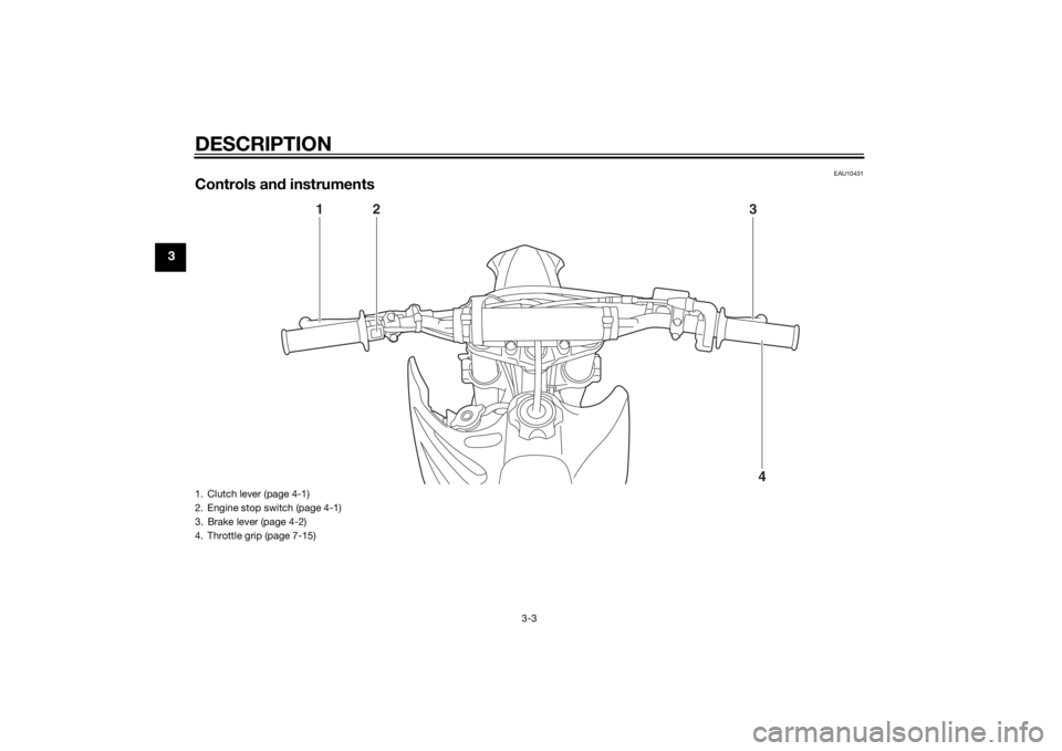
Controls and instruments
4
13
2
1. Clutch lever (page 4-1)
2. Engine stop switch (page 4-1)
3. Brake lever (page 4-2)
4. Throttle grip (page 7-15)U1SN83E0.book Page 3 Monday, September 8, 2014 2:36 PM
Page 27 of 88
INSTRUMENT AND CONTROL FUNCTIONS
4-1
4
EAU40661
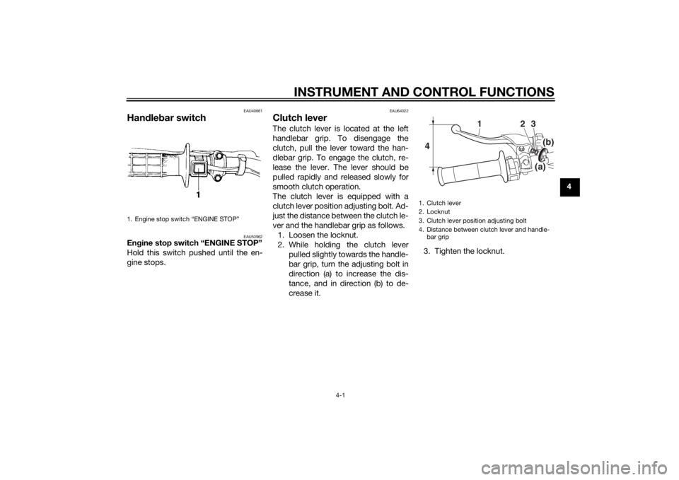
Handle bar switch
EAU53962
En gine stop switch “ENGINE STOP”
Hold this switch pushed until the en-
gine stops.
EAU64022
Clutch leverThe clutch lever is located at the left
handlebar grip. To disengage the
clutch, pull the lever toward the han-
dlebar grip. To engage the clutch, re-
lease the lever. The lever should be
pulled rapidly and released slowly for
smooth clutch operation.
The clutch lever is equipped with a
clutch lever position adjusting bolt. Ad-
just the distance between the clutch le-
ver and the handlebar grip as follows. 1. Loosen the locknut.
2. While holding the clutch lever pulled slightly towards the handle-
bar grip, turn the adjusting bolt in
direction (a) to increase the dis-
tance, and in direction (b) to de-
crease it. 3. Tighten the locknut.
1. Engine stop switch “ENGINE STOP”
1. Clutch lever
2. Locknut
3. Clutch lever position adjusting bolt
4. Distance between clutch lever and handle-
bar grip4
2
1
3
(b)(a)
U1SN83E0.book Page 1 Monday, September 8, 2014 2:36 PM
Page 28 of 88
INSTRUMENT AND CONTROL FUNCTIONS
4-2
4
EAU12872
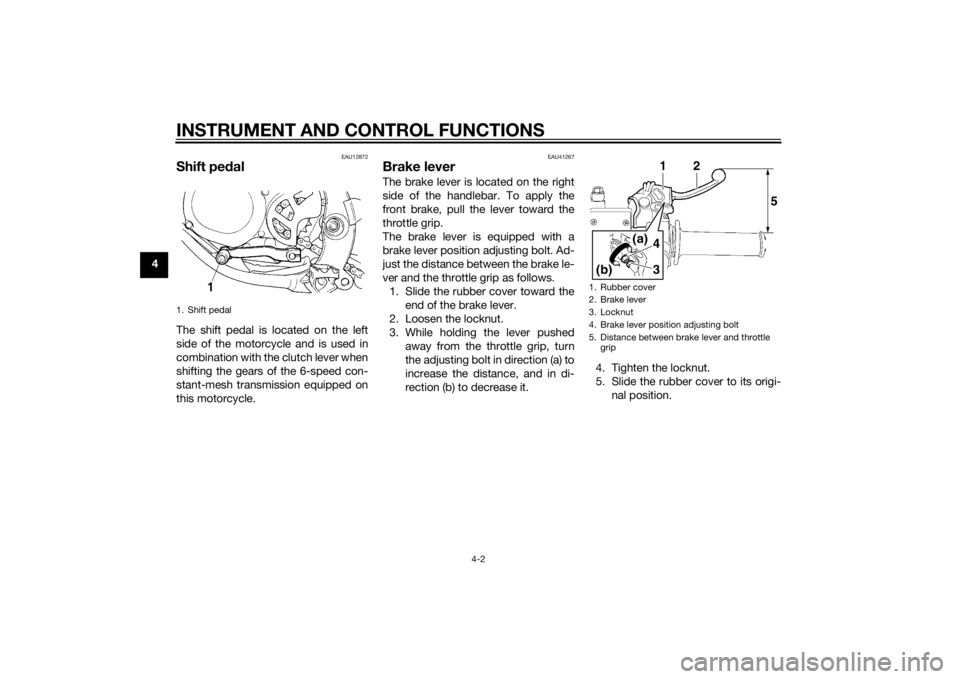
Shift pedalThe shift pedal is located on the left
side of the motorcycle and is used in
combination with the clutch lever when
shifting the gears of the 6-speed con-
stant-mesh transmission equipped on
this motorcycle.
EAU41267
Brake leverThe brake lever is located on the right
side of the handlebar. To apply the
front brake, pull the lever toward the
throttle grip.
The brake lever is equipped with a
brake lever position adjusting bolt. Ad-
just the distance between the brake le-
ver and the throttle grip as follows.
1. Slide the rubber cover toward the end of the brake lever.
2. Loosen the locknut.
3. While holding the lever pushed away from the throttle grip, turn
the adjusting bolt in direction (a) to
increase the distance, and in di-
rection (b) to decrease it. 4. Tighten the locknut.
5. Slide the rubber cover to its origi-
nal position.
1. Shift pedal
1. Rubber cover
2. Brake lever
3. Locknut
4. Brake lever position adjusting bolt
5. Distance between brake lever and throttle grip
143
(a)
(b)
2
5
U1SN83E0.book Page 2 Monday, September 8, 2014 2:36 PM
Page 33 of 88
INSTRUMENT AND CONTROL FUNCTIONS
4-7
4
EAU13651
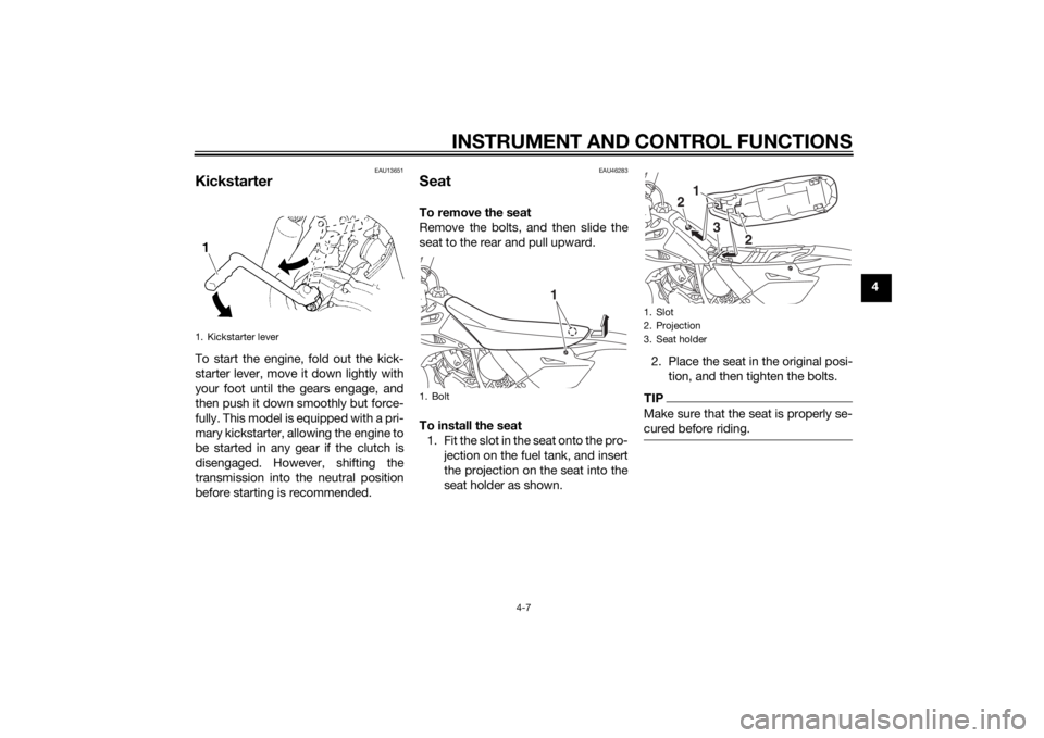
KickstarterTo start the engine, fold out the kick-
starter lever, move it down lightly with
your foot until the gears engage, and
then push it down smoothly but force-
fully. This model is equipped with a pri-
mary kickstarter, allowing the engine to
be started in any gear if the clutch is
disengaged. However, shifting the
transmission into the neutral position
before starting is recommended.
EAU46283
SeatTo remove the seat
Remove the bolts, and then slide the
seat to the rear and pull upward.
To install the seat1. Fit the slot in the seat onto the pro- jection on the fuel tank, and insert
the projection on the seat into the
seat holder as shown. 2. Place the seat in the original posi-
tion, and then tighten the bolts.
TIPMake sure that the seat is properly se-
cured before riding.
1. Kickstarter lever
1. Bolt
1
1. Slot
2. Projection
3. Seat holder
1
2
3
2
U1SN83E0.book Page 7 Monday, September 8, 2014 2:36 PM
Page 40 of 88

FOR YOUR SAFETY – PRE-OPERATION CHECKS
5-2
5
Rear brake • Check operation.
• If soft or spongy, have Yamaha dealer bleed hydraulic system.
• Check brake pads for wear.
• Replace if necessary.
• Check fluid level in reservoir.
• If necessary, add specified brake fluid to specified level.
• Check hydraulic system for leakage. 7-20, 7-20
Clutch • Check operation.
• Lubricate cable if necessary.
• Check lever free play.
• Adjust if necessary.
7-18
Throttle g rip • Make sure that operation is smooth.
• Check throttle grip free play.
• If necessary, adjust throttle grip free play. 7-15, 7-24
Drive chain • Check chain slack.
• Adjust if necessary.
• Check chain condition.
• Lubricate if necessary. 7-22, 7-23
Wheels an d tires •Check for damage.
• Check tire condition and tread depth.
• Check air pressure.
• Correct if necessary.
• Check for loose spokes and tighten if necessary. 7-15, 7-17
Shift pe dal • Make sure that operation is smooth.
• Correct if necessary.
7-19
Brake ped al • Make sure that operation is smooth.
• Lubricate pedal pivoting point if necessary. 7-25
Brake an d clutch levers • Make sure that operation is smooth.
• Lubricate lever pivoting points if necessary.
7-24
Steerin g • Check that the handlebar can be turned smoothly and has no excessive play. 7-27
ITEM CHECKS PAGE
U1SN83E0.book Page 2 Monday, September 8, 2014 2:36 PM
Page 43 of 88
OPERATION AND IMPORTANT RIDING POINTS
6-2
6
EAU16673
ShiftingShifting gears lets you control the
amount of engine power available for
starting off, accelerating, climbing hills,
etc.
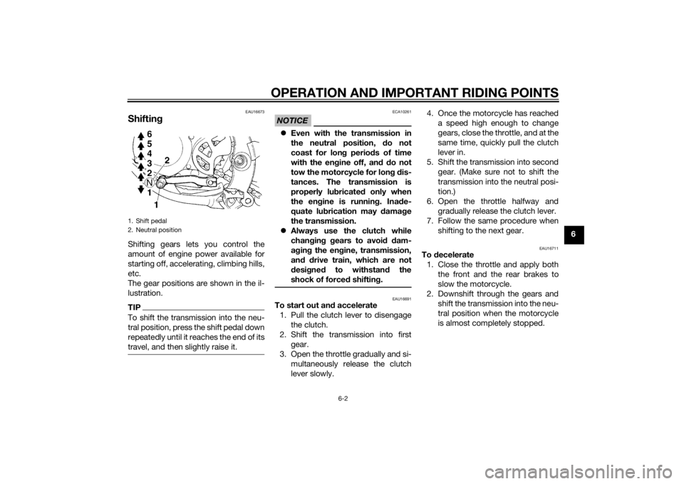
The gear positions are shown in the il-
lustration.TIPTo shift the transmission into the neu-
tral position, press the shift pedal down
repeatedly until it reaches the end of its
travel, and then slightly raise it.
NOTICE
ECA10261
Even with the transmission in
the neutral position, do not
coast for lon g period s of time
with the eng ine off, and d o not
tow the motorcycle for lon g d is-
tances. The transmission is
properly lu bricated only when
the en gine is runnin g. Ina de-
quate lu brication may damag e
the transmission.
Always use the clutch while
chan gin g g ears to avoi d d am-
a g in g the en gine, transmission,
an d d rive train, which are not
d esi gne d to withstan d the
shock of forced shifting.
EAU16691
To start out an d accelerate
1. Pull the clutch lever to disengage the clutch.
2. Shift the transmission into first gear.
3. Open the throttle gradually and si- multaneously release the clutch
lever slowly. 4. Once the motorcycle has reached
a speed high enough to change
gears, close the throttle, and at the
same time, quickly pull the clutch
lever in.
5. Shift the transmission into second gear. (Make sure not to shift the
transmission into the neutral posi-
tion.)
6. Open the throttle halfway and gradually release the clutch lever.
7. Follow the same procedure when shifting to the next gear.
EAU16711
To decelerate
1. Close the throttle and apply both the front and the rear brakes to
slow the motorcycle.
2. Downshift through the gears and shift the transmission into the neu-
tral position when the motorcycle
is almost completely stopped.
1. Shift pedal
2. Neutral position
U1SN83E0.book Page 2 Monday, September 8, 2014 2:36 PM
Page 48 of 88
PERIODIC MAINTENANCE AND ADJUSTMENT
7-3
7
√
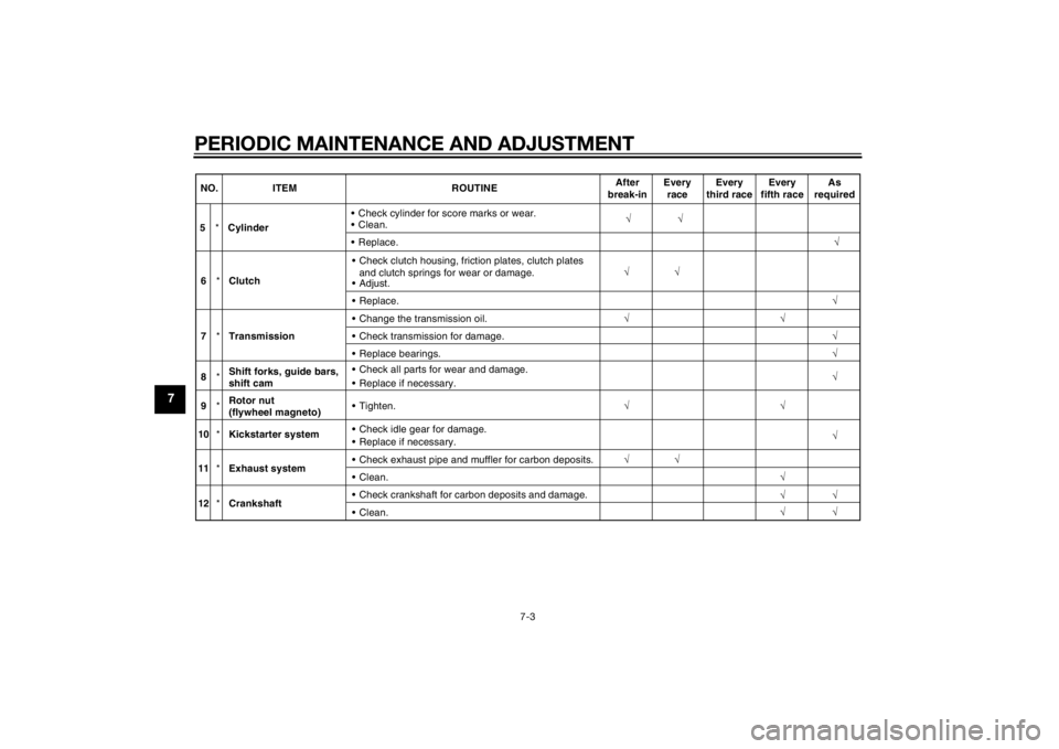
5 *Cylinder • Check cylinder for score marks or wear.
Clean.
√
Replace. √
NO. ITEM ROUTINE
After
break-in Every
race Every
third race Every
fifth race As
required
6 *Clutch Check clutch housing, friction plates, clutch plates
and clutch springs for wear or damage.
Adjust. √
√
Replace. √
7 *Transmission Change the transmission oil.
√
Check transmission for damage. √
Replace bearings. √
8 *Shift forks, guide bars,
shift cam
Replace if necessary. Check all parts for wear and damage.
√
9 *Rotor nut
(flywheel
magneto) Tighten.
√√√
10 *Kickstarter system Check idle gear for damage.
√
Replace if necessary.
11 *Exhaust system Check exhaust pipe and muffler for carbon deposits.
√
√
Clean. √
√
√
√
√
12
*Crankshaft Check crankshaft for carbon deposits and damage.
Clean.
U1SN83E0.book Page 3 Monday, September 8, 2014 2:36 PM
Page 55 of 88
PERIODIC MAINTENANCE AND ADJUSTMENT
7-10
7
NOTICE
ECA10453
In or der to prevent clutch slip-
pa ge (since the transmission oil
also lu bricates the clutch), do
not mix any chemical additives.
Do not use oils with a d iesel
specification of “CD” or oils of a
hi gher quality than specifie d. In
a ddition, do not use oils lab eled
“ENERGY CONSERVING II” or
hi gher.
Make sure that no forei gn mate-
rial enters the transmission.7. Start the engine, and then let it idle for several minutes while checking
it for oil leakage. If oil is leaking,
immediately turn the engine off
and check for the cause.
EAU20071
CoolantThe coolant level should be checked
before each ride. In addition, the cool-
ant must be changed at the intervals
specified in the periodic maintenance
and lubrication chart.
EAUM1296
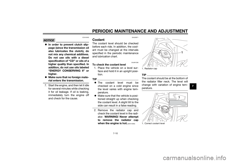
To check the coolant level1. Place the vehicle on a level sur- face and hold it in an upright posi-
tion.TIPThe coolant level must be
checked on a cold engine since
the level varies with engine tem-
perature.
Make sure that the vehicle is posi-
tioned straight up when checking
the coolant level. A slight tilt to the
side can result in a false reading.2. Remove the radiator cap and
check the coolant level in the radi-
ator. WARNING! Never attempt
to remove the ra diator cap
when the en gine is hot.
[EWA10382]
TIPThe coolant should be at the bottom of
the radiator filler neck. The level will
change with variation of engine tem-
perature.1. Radiator cap
1. Correct coolant level
1
1
U1SN83E0.book Page 10 Monday, September 8, 2014 2:36 PM
Page 63 of 88
PERIODIC MAINTENANCE AND ADJUSTMENT
7-18
7
EAU65772
Adjustin g the clutch lever free
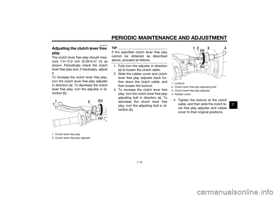
playThe clutch lever free play should mea-
sure 7.0–12.0 mm (0.28–0.47 in) as
shown. Periodically check the clutch
lever free play and, if necessary, adjust
it.
To increase the clutch lever free play,
turn the clutch lever free play adjuster
in direction (a). To decrease the clutch
lever free play, turn the adjuster in di-
rection (b).
TIPIf the specified clutch lever free play
cannot be obtained as described
above, proceed as follows.1. Fully turn the adjuster in direction
(a) to loosen the clutch cable.
2. Slide the rubber cover and clutch lever free play adjuster back fur-
ther down the clutch cable, and
then loosen the locknut.
3. To increase the clutch lever free play, turn the clutch lever free play
adjusting bolt in direction (a). To
decrease the clutch lever free
play, turn the adjusting bolt in di-
rection (b). 4. Tighten the locknut at the clutch
cable, and then slide the clutch le-
ver free play adjuster and rubber
cover to their original positions.
1. Clutch lever free play
2. Clutch lever free play adjuster1
2
(b)(a)
1. Locknut
2. Clutch lever free play adjusting bolt
3. Clutch lever free play adjuster
4. Rubber cover
1
2
3
4
(a)(b)
U1SN83E0.book Page 18 Monday, September 8, 2014 2:36 PM