clutch YAMAHA YZF-R1 2001 User Guide
[x] Cancel search | Manufacturer: YAMAHA, Model Year: 2001, Model line: YZF-R1, Model: YAMAHA YZF-R1 2001Pages: 116, PDF Size: 12.72 MB
Page 53 of 116
PERIODIC MAINTENANCE AND MINOR REPAIR
6-2
6
EAU03540
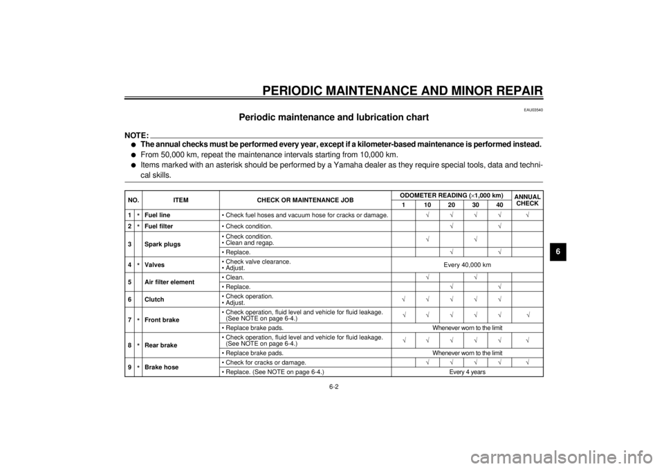
Periodic maintenance and lubrication chart
NOTE:@ l
The annual checks must be performed every year, except if a kilometer-based maintenance is performed instead.
l
From 50,000 km, repeat the maintenance intervals starting from 10,000 km.
l
Items marked with an asterisk should be performed by a Yamaha dealer as they require special tools, data and techni-
cal skills.
@CP-03ENO. ITEM CHECK OR MAINTENANCE JOBODOMETER READING (´1,000 km)
ANNUAL
CHECK
1 10203040
1
*Fuel line• Check fuel hoses and vacuum hose for cracks or damage.ÖÖÖÖ Ö
2*Fuel filter• Check condition.ÖÖ
3 Spark plugs• Check condition.
• Clean and regap.ÖÖ
• Replace.ÖÖ
4*Valves• Check valve clearance.
•Adjust.Every 40,000 km
5 Air filter element•Clean.ÖÖ
• Replace.ÖÖ
6Clutch• Check operation.
•Adjust.ÖÖÖÖÖ
7*Front brake• Check operation, fluid level and vehicle for fluid leakage.
(See NOTE on page 6-4.)ÖÖÖÖÖ Ö
• Replace brake pads. Whenever worn to the limit
8*Rear brake• Check operation, fluid level and vehicle for fluid leakage.
(See NOTE on page 6-4.)ÖÖÖÖÖ Ö
• Replace brake pads. Whenever worn to the limit
9*Brake hose• Check for cracks or damage.ÖÖÖÖ Ö
• Replace. (See NOTE on page 6-4.) Every 4 years
E_5jj.book Page 2 Friday, September 8, 2000 3:33 PM
Page 62 of 116

PERIODIC MAINTENANCE AND MINOR REPAIR
6-11
68. Install the new oil filter cartridge,
and then tighten it to the specified
torque with a torque wrench.
9. Install the engine oil drain bolt, and
then tighten it to the specified
torque.10. Add the specified amount of the
recommended engine oil, and
then install and tighten the oil filler
cap.
EC000072
CAUTION:@ l
In order to prevent clutch slip-
page (since the engine oil also
lubricates the clutch), do not
mix any chemical additives with
the oil or use oils of a higher
grade than “CD”. In addition, do
not use oils labeled “ENERGY
CONSERVING II” or higher.
l
Make sure that no foreign mate-
rial enters the crankcase.
@11. Start the engine, and then let it idle
for several minutes while checking
it for oil leakage. If oil is leaking,
immediately turn the engine off
and check for the cause.NOTE:@ After the engine is started, the engine
oil level warning light should go off if the
oil level is sufficient. @
EC000067
CAUTION:@ If the oil level warning light flickers
or remains on, immediately turn the
engine off and have a Yamaha deal-
er check the vehicle. @12. Turn the engine off, and then
check the oil level and correct it if
necessary.
13. Install the cowling stay by install-
ing the bolt.
14. Install the cowling.
1. Torque wrenchTightening torque:
Oil filter cartridge:
17 Nm (1.7 m·kg)
Tightening torque:
Engine oil drain bolt:
43 Nm (4.3 m·kg)
Recommended engine oil:
See page 8-1.
Oil quantity:
Without oil filter cartridge
replacement:
2.7 L
With oil filter cartridge
replacement:
2.9 L
Total amount (dry engine):
3.6 L
E_5jj.book Page 11 Friday, September 8, 2000 3:33 PM
Page 64 of 116
PERIODIC MAINTENANCE AND MINOR REPAIR
6-13
6
NOTE:@ l
The radiator fan is automatically
switched on or off according to the
coolant temperature in the
radiator.
l
When the engine is idling with the
starter (choke) turned on, the radi-
ator fan will automatically be
switched on and off regardless of
the coolant temperature, but this
does not indicate a malfunction.
l
If the engine overheats, see page
6-44 for further instructions.
@
EAU01577
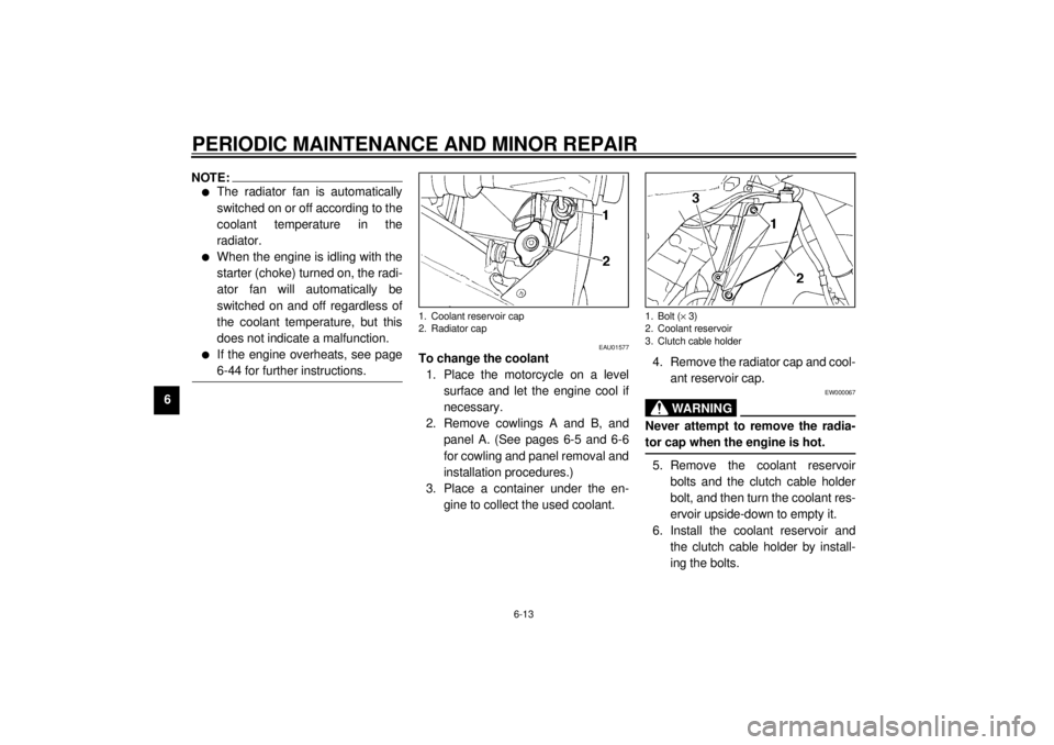
To change the coolant
1. Place the motorcycle on a level
surface and let the engine cool if
necessary.
2. Remove cowlings A and B, and
panel A. (See pages 6-5 and 6-6
for cowling and panel removal and
installation procedures.)
3. Place a container under the en-
gine to collect the used coolant.4. Remove the radiator cap and cool-
ant reservoir cap.
EW000067
WARNING
@ Never attempt to remove the radia-
tor cap when the engine is hot. @5. Remove the coolant reservoir
bolts and the clutch cable holder
bolt, and then turn the coolant res-
ervoir upside-down to empty it.
6. Install the coolant reservoir and
the clutch cable holder by install-
ing the bolts.
1. Coolant reservoir cap
2. Radiator cap
1. Bolt (´ 3)
2. Coolant reservoir
3. Clutch cable holder
E_5jj.book Page 13 Friday, September 8, 2000 3:33 PM
Page 73 of 116

PERIODIC MAINTENANCE AND MINOR REPAIR
6-22
6
EAU00687
WheelsTo maximize the performance, durabil-
ity, and safe operation of your motor-
cycle, note the following points
regarding the specified wheels.l
The wheel rims should be checked
for cracks, bends or warpage be-
fore each ride. If any damage is
found, have a Yamaha dealer re-
place the wheel. Do not attempt
even the smallest repair to the
wheel. A deformed or cracked
wheel must be replaced.
l
The wheel should be balanced
whenever either the tire or wheel
has been changed or replaced. An
unbalanced wheel can result in
poor performance, adverse han-
dling characteristics, and a short-
ened tire life.
l
Ride at moderate speeds after
changing a tire since the tire sur-
face must first be “broken in” for it to
develop its optimal characteristics.
EAU01356
Adjusting the clutch lever free
play The clutch lever free play should mea-
sure 10–15 mm as shown. Periodically
check the clutch lever free play and, if
necessary, adjust it as follows.
To increase the clutch lever free play,
turn the adjusting bolt at the clutch le-
ver in direction
a. To decrease the
clutch lever free play, turn the adjusting
bolt in direction
b.
NOTE:@ If the specified clutch lever free play
cannot be obtained as described
above, proceed as follows. @1. Fully turn the adjusting bolt at the
clutch lever in direction
a to loos-
en the clutch cable.
1. Adjusting bolt
c. Clutch lever free play
E_5jj.book Page 22 Friday, September 8, 2000 3:33 PM
Page 74 of 116
PERIODIC MAINTENANCE AND MINOR REPAIR
6-23
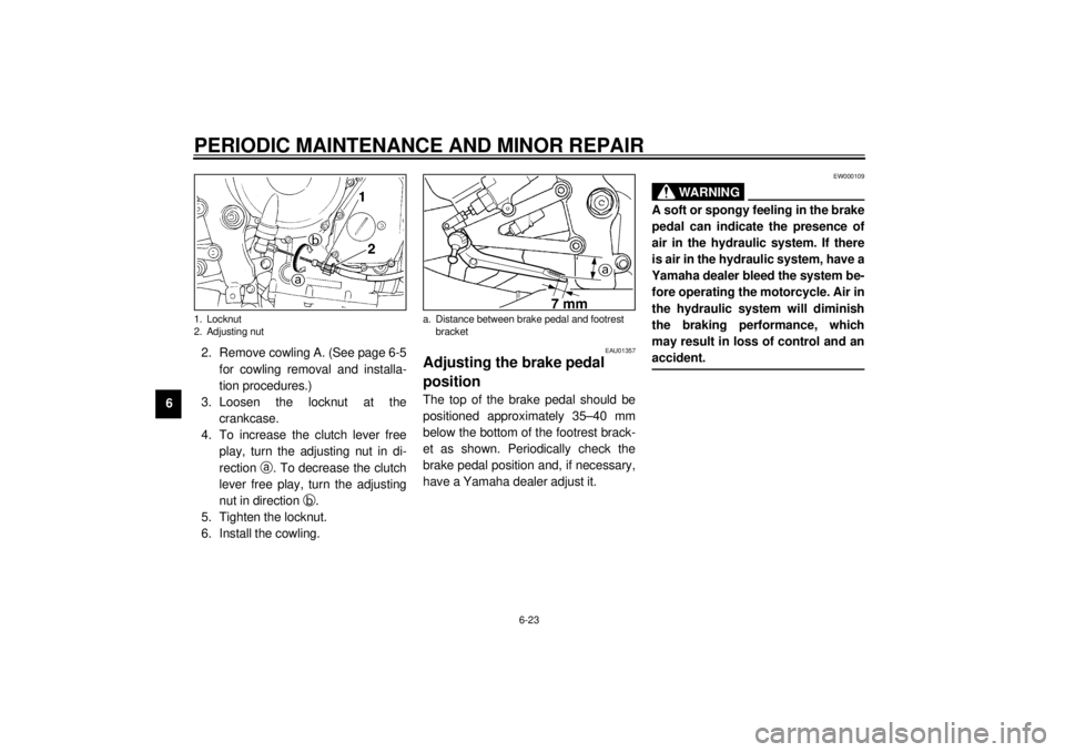
62. Remove cowling A. (See page 6-5
for cowling removal and installa-
tion procedures.)
3. Loosen the locknut at the
crankcase.
4. To increase the clutch lever free
play, turn the adjusting nut in di-
rection
a. To decrease the clutch
lever free play, turn the adjusting
nut in direction
b.
5. Tighten the locknut.
6. Install the cowling.
EAU01357
Adjusting the brake pedal
position The top of the brake pedal should be
positioned approximately 35–40 mm
below the bottom of the footrest brack-
et as shown. Periodically check the
brake pedal position and, if necessary,
have a Yamaha dealer adjust it.
EW000109
WARNING
@ A soft or spongy feeling in the brake
pedal can indicate the presence of
air in the hydraulic system. If there
is air in the hydraulic system, have a
Yamaha dealer bleed the system be-
fore operating the motorcycle. Air in
the hydraulic system will diminish
the braking performance, which
may result in loss of control and an
accident. @
1. Locknut
2. Adjusting nut
a. Distance between brake pedal and footrest
bracket
E_5jj.book Page 23 Friday, September 8, 2000 3:33 PM
Page 81 of 116

PERIODIC MAINTENANCE AND MINOR REPAIR
6-30
6
EAU03164
Checking and lubricating the
brake and clutch levers The operation of the brake and clutch
levers should be checked before each
ride, and the lever pivots should be lu-
bricated if necessary.
EAU03163
Lubricating the brake pedal The operation of the brake pedal
should be checked before each ride,
and the pedal pivot should be lubricat-
ed if necessary.
EAU03165
Checking and lubricating the
sidestand The operation of the sidestand should
be checked before each ride, and the
sidestand pivot and metal-to-metal
contact surfaces should be lubricated if
necessary.
EW000113
WARNING
@ If the sidestand does not move up
and down smoothly, have a Yamaha
dealer check or repair it. @
Recommended lubricant:
Lithium-soap-based grease
(all-purpose grease)
Recommended lubricant:
Lithium-soap-based grease
(all-purpose grease)
Recommended lubricant:
Lithium-soap-based grease
(all-purpose grease)
E_5jj.book Page 30 Friday, September 8, 2000 3:33 PM
Page 104 of 116

8-1
8
EAU01038
8-SPECIFICATIONSSpecificationsCS-01E
Model YZF-R1
Dimensions
Overall length 2,035 mm
Overall width 695 mm
Overall height 1,105 mm
Seat height 815 mm
Wheelbase 1,395 mm
Ground clearance 140 mm
Minimum turning radius 3,400 mm
Basic weight (with oil and full
fuel tank)
194 kg
Engine
Engine type Liquid-cooled 4-stroke, DOHC
Cylinder arrangement Forward-inclined parallel
4-cylinder
Displacement 998 cm
3
Bore ´ stroke 74 ´ 58 mm
Compression ratio 11.8:1
Starting system Electric starter
Lubrication system Wet sumpEngine oil
Ty p e
Recommended engine oil
classification API Service SE, SF, SG or
higher
Quantity
Without oil filter cartridge
replacement 2.7 L
With oil filter car tridge
replacement 2.9 L
Total amount (dry engine) 3.6 L
-20 -10 0
10 20 30
40
50 ˚C
SAE 10W-30
SAE 15W-40SAE 20W-40SAE 20W-50
SAE 10W-40
CAUTION:Be sure to use motor oils that do not contain anti-friction
modifiers. Passenger car motor oils (often labeled
“ENERGY CONSERVING II”) contain anti-friction additives
which will cause clutch and/or starter clutch slippage, result-
ing in reduced component life and poor engine performance.
E_5jj.book Page 1 Friday, September 8, 2000 3:33 PM
Page 105 of 116

SPECIFICATIONS
8-2
8
Cooling system capacity
(total amount)
2.55 L
Air filterDry type element
Fuel
Type Regular unleaded gasoline
Fuel tank capacity 18 L
Fuel reserve amount 3.8 L
Carburetor
Manufacturer MIKUNI
Model ´ quantity BDSR40 ´ 4
Spark plug
Manufacturer/model NGK / CR9E or
DENSO / U27ESR-N
Gap 0.7–0.8 mm
Clutch typeWet, multiple-disc
Transmission
Primary reduction system Spur gear
Primary reduction ratio 1.581
Secondary reduction system Chain drive
Secondary reduction ratio 2.688
Number of drive chain
sprocket teeth (rear/front) 16/43
Transmission type Constant-mesh 6-speed
Operation Left footGear ratio
1st 2.500
2nd 1.842
3rd 1.500
4th 1.333
5th 1.200
6th 1.115
Chassis
Frame type Diamond
Caster angle 24°
Trail 92 mm
Tires
Front
Type Tubeless
Size 120/70 ZR17 (58 W)
Manufacturer/
model Metzeler / MEZ3Y Front
Dunlop / D207FQ
Rear
Type Tubeless
Size 190/50 ZR17 (73 W)
Manufacturer/
model Metzeler / MEZ3Y
Dunlop / D207N
E_5jj.book Page 2 Friday, September 8, 2000 3:33 PM
Page 112 of 116
INDEXAAir filter element, cleaning ...................... 6-15
Anti-theft alarm (optional) .........................3-8BBattery ................................................... 6-33
Brake and clutch levers, checking and
lubricating ............................................ 6-30
Brake fluid, changing ............................. 6-26
Brake fluid level, checking...................... 6-25
Brake lever............................................. 3-11
Brake light switch (rear), adjusting ......... 6-24
Brake pads, checking............................. 6-24
Brake pedal............................................ 3-11
Brake pedal, lubricating.......................... 6-30
Brake pedal position, adjusting .............. 6-23CCables, checking and lubricating............ 6-29
Carburetors, adjusting............................ 6-17
Care.........................................................7-1
Clutch lever ............................................ 3-10
Clutch lever free play, adjusting ............. 6-22
Conversion table ......................................8-5
Coolant .................................................. 6-12
Changing .......................................... 6-13
Checking .......................................... 6-12
Coolant temperature warning light............3-3
Cowlings and panels, removing and
installing ................................................6-5DDimmer switch .........................................3-9
Drive chain, lubricating ........................... 6-28
Drive chain slack ................................... 6-27
Adjusting .......................................... 6-27
Checking .......................................... 6-27EEngine break-in ....................................... 5-4
Engine oil and oil filter cartridge ............... 6-9
Engine stop switch................................... 3-9
EXUP system ........................................ 3-22FFront and rear suspension settings ........ 3-21
Front fork, adjusting ............................... 3-16
Front fork, checking ............................... 6-31
Fuel ....................................................... 3-12
Fuel consumption, tips for reducing ......... 5-4
Fuel level warning light ............................ 3-2
Fuel tank breather hose ......................... 3-13
Fuel tank cap ......................................... 3-11
Fuses, replacing .................................... 6-34HHandlebar switches ................................. 3-9
Headlight bulb, replacing ....................... 6-35
Helmet holders ...................................... 3-15
High beam indicator light ......................... 3-2
Horn switch ............................................. 3-9IIdentification numbers ............................. 9-1
Idling speed, adjusting ........................... 6-18
Ignition circuit cut-off system.................. 3-23
Indicator and warning lights ..................... 3-2
KKey identification number .........................9-1LLight switch ..............................................3-9
Luggage strap holders ...........................3-22MMain switch/steering lock .........................3-1
Model label ..............................................9-2NNeutral indicator light ...............................3-2OOil level warning light ...............................3-3PParking.....................................................5-5
Part locations ...........................................2-1
Pass switch ..............................................3-9
Periodic maintenance and lubrication
chart ......................................................6-2
Pre-operation check list ............................4-1SSafety information ....................................1-1
Seats .....................................................3-14
Passenger seat .................................. 3-14
Rider seat .........................................3-14
Self-diagnosis devices .............................3-7
Shifting .....................................................5-3
Shift pedal ..............................................3-10
Shift points (for Switzerland only) .............5-4
Shock absorber assembly, adjusting ......3-18
Sidestand ...............................................3-23
E_5jj.book Page 1 Friday, September 8, 2000 3:33 PM