key YAMAHA YZF-R1 2001 User Guide
[x] Cancel search | Manufacturer: YAMAHA, Model Year: 2001, Model line: YZF-R1, Model: YAMAHA YZF-R1 2001Pages: 116, PDF Size: 12.72 MB
Page 50 of 116
OPERATION AND IMPORTANT RIDING POINTS
5-5
5
EAU03172*
0–1,000 km
Avoid prolonged operation above
5,000 r/min.
1,000–1,600 km
Avoid prolonged operation above
6,000 r/min.
EC000052*
CAUTION:@ After 1,000 km of operation, the en-
gine oil must be changed and the oil
filter cartridge replaced. @1,600 km and beyond
The vehicle can now be operated
normally.
EC000053
CAUTION:@ l
Keep the engine speed out of
the tachometer red zone.
l
If any engine trouble should oc-
cur during the engine break-in
period, immediately have a
Yamaha dealer check the
vehicle.
@
NOTE:During and after the engine break-in
period, the exhaust heat may cause
discoloration of the exhaust pipe, but
this is normal.
EAU00460
ParkingWhen parking, stop the engine, and
then remove the key from the main
switch.
EW000058
WARNING
@ l
Since the engine and exhaust
system can become very hot,
park in a place where pedestri-
ans or children are not likely to
touch them.
l
Do not park on a slope or on
soft ground, otherwise the
motorcycle may overturn.
@
E_5jj.book Page 5 Friday, September 8, 2000 3:33 PM
Page 85 of 116
PERIODIC MAINTENANCE AND MINOR REPAIR
6-34
6
EC000102
CAUTION:@ l
Always keep the battery
charged. Storing a discharged
battery can cause permanent
battery damage.
l
To charge a sealed-type (MF)
battery, a special (constant-
voltage) battery charger is re-
quired. Using a conventional
battery charger will damage the
battery. If you do not have ac-
cess to a sealed-type (MF) bat-
tery charger, have a Yamaha
dealer charge your battery.
@
EAU03610
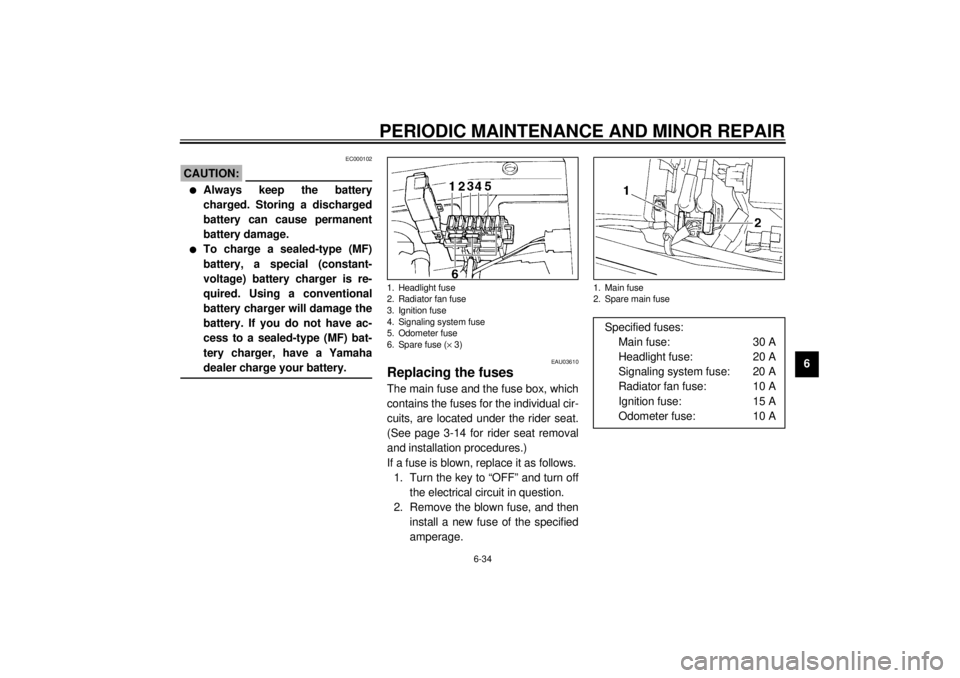
Replacing the fuses The main fuse and the fuse box, which
contains the fuses for the individual cir-
cuits, are located under the rider seat.
(See page 3-14 for rider seat removal
and installation procedures.)
If a fuse is blown, replace it as follows.
1. Turn the key to “OFF” and turn off
the electrical circuit in question.
2. Remove the blown fuse, and then
install a new fuse of the specified
amperage.1. Headlight fuse
2. Radiator fan fuse
3. Ignition fuse
4. Signaling system fuse
5. Odometer fuse
6. Spare fuse (´ 3)
1. Main fuse
2. Spare main fuseSpecified fuses:
Main fuse: 30 A
Headlight fuse: 20 A
Signaling system fuse: 20 A
Radiator fan fuse: 10 A
Ignition fuse: 15 A
Odometer fuse: 10 A
E_5jj.book Page 34 Friday, September 8, 2000 3:33 PM
Page 86 of 116
PERIODIC MAINTENANCE AND MINOR REPAIR
6-35
6
EC000103
CAUTION:@ Do not use a fuse of a higher amper-
age rating than recommended to
avoid causing extensive damage to
the electrical system and possibly a
fire. @3. Turn the key to “ON” and turn on
the electrical circuit in question to
check if the device operates.
4. If the fuse immediately blows
again, have a Yamaha dealer
check the electrical system.
EAU00826
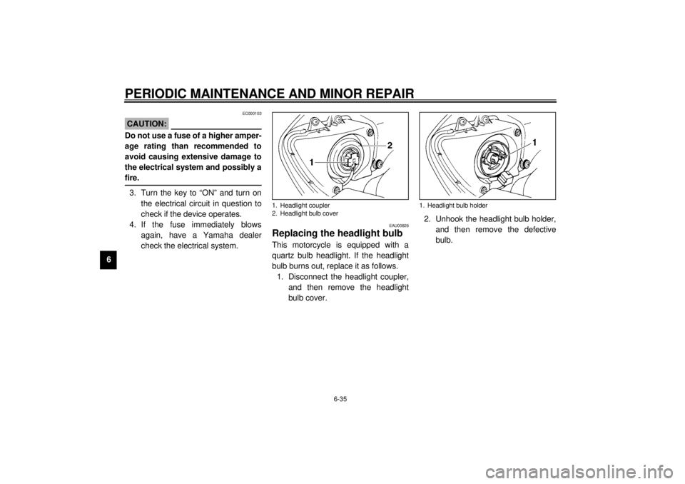
Replacing the headlight bulb This motorcycle is equipped with a
quartz bulb headlight. If the headlight
bulb burns out, replace it as follows.
1. Disconnect the headlight coupler,
and then remove the headlight
bulb cover.2. Unhook the headlight bulb holder,
and then remove the defective
bulb.1. Headlight coupler
2. Headlight bulb cover
1. Headlight bulb holder
E_5jj.book Page 35 Friday, September 8, 2000 3:33 PM
Page 109 of 116
CONSUMER INFORMATION
9
Identification numbers ........................................................................ 9-1
Key identification number ................................................................... 9-1
Vehicle identification number.............................................................. 9-1
Model label ........................................................................................ 9-2
E_5jj.book Page 1 Friday, September 8, 2000 3:33 PM
Page 110 of 116
9-1
9
10
EAU01039
9-CONSUMER INFORMATION
EAU02944
Identification numbersRecord the key identification number,
vehicle identification number and
model label information in the spaces
provided below for assistance when or-
dering spare parts from a Yamaha
dealer or for reference in case the vehi-
cle is stolen.
1. KEY IDENTIFICATION NUMBER:CA-02E2. VEHICLE IDENTIFICATION
NUMBER:CA-02E3. MODEL LABEL INFORMATION:CA-01EEAU01041
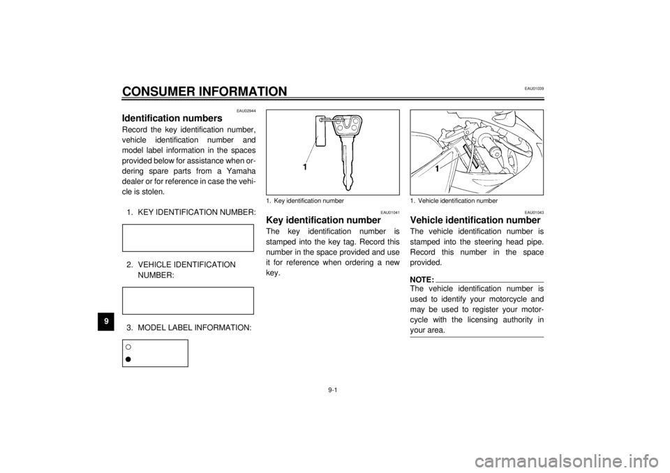
Key identification numberThe key identification number is
stamped into the key tag. Record this
number in the space provided and use
it for reference when ordering a new
key.
EAU01043
Vehicle identification numberThe vehicle identification number is
stamped into the steering head pipe.
Record this number in the space
provided.NOTE:@ The vehicle identification number is
used to identify your motorcycle and
may be used to register your motor-
cycle with the licensing authority in
your area. @
1. Key identification number
1. Vehicle identification number
E_5jj.book Page 1 Friday, September 8, 2000 3:33 PM
Page 112 of 116
INDEXAAir filter element, cleaning ...................... 6-15
Anti-theft alarm (optional) .........................3-8BBattery ................................................... 6-33
Brake and clutch levers, checking and
lubricating ............................................ 6-30
Brake fluid, changing ............................. 6-26
Brake fluid level, checking...................... 6-25
Brake lever............................................. 3-11
Brake light switch (rear), adjusting ......... 6-24
Brake pads, checking............................. 6-24
Brake pedal............................................ 3-11
Brake pedal, lubricating.......................... 6-30
Brake pedal position, adjusting .............. 6-23CCables, checking and lubricating............ 6-29
Carburetors, adjusting............................ 6-17
Care.........................................................7-1
Clutch lever ............................................ 3-10
Clutch lever free play, adjusting ............. 6-22
Conversion table ......................................8-5
Coolant .................................................. 6-12
Changing .......................................... 6-13
Checking .......................................... 6-12
Coolant temperature warning light............3-3
Cowlings and panels, removing and
installing ................................................6-5DDimmer switch .........................................3-9
Drive chain, lubricating ........................... 6-28
Drive chain slack ................................... 6-27
Adjusting .......................................... 6-27
Checking .......................................... 6-27EEngine break-in ....................................... 5-4
Engine oil and oil filter cartridge ............... 6-9
Engine stop switch................................... 3-9
EXUP system ........................................ 3-22FFront and rear suspension settings ........ 3-21
Front fork, adjusting ............................... 3-16
Front fork, checking ............................... 6-31
Fuel ....................................................... 3-12
Fuel consumption, tips for reducing ......... 5-4
Fuel level warning light ............................ 3-2
Fuel tank breather hose ......................... 3-13
Fuel tank cap ......................................... 3-11
Fuses, replacing .................................... 6-34HHandlebar switches ................................. 3-9
Headlight bulb, replacing ....................... 6-35
Helmet holders ...................................... 3-15
High beam indicator light ......................... 3-2
Horn switch ............................................. 3-9IIdentification numbers ............................. 9-1
Idling speed, adjusting ........................... 6-18
Ignition circuit cut-off system.................. 3-23
Indicator and warning lights ..................... 3-2
KKey identification number .........................9-1LLight switch ..............................................3-9
Luggage strap holders ...........................3-22MMain switch/steering lock .........................3-1
Model label ..............................................9-2NNeutral indicator light ...............................3-2OOil level warning light ...............................3-3PParking.....................................................5-5
Part locations ...........................................2-1
Pass switch ..............................................3-9
Periodic maintenance and lubrication
chart ......................................................6-2
Pre-operation check list ............................4-1SSafety information ....................................1-1
Seats .....................................................3-14
Passenger seat .................................. 3-14
Rider seat .........................................3-14
Self-diagnosis devices .............................3-7
Shifting .....................................................5-3
Shift pedal ..............................................3-10
Shift points (for Switzerland only) .............5-4
Shock absorber assembly, adjusting ......3-18
Sidestand ...............................................3-23
E_5jj.book Page 1 Friday, September 8, 2000 3:33 PM