ESP YAMAHA YZF-R1 2015 Owners Manual
[x] Cancel search | Manufacturer: YAMAHA, Model Year: 2015, Model line: YZF-R1, Model: YAMAHA YZF-R1 2015Pages: 126, PDF Size: 9.02 MB
Page 8 of 126

1-1
1
2
3
4
5
6
7
8
9
10
11
12
SAFETY INFORMATION
EAU1028B
Be a Responsible Owner
As the vehicle’s owner, you are respon-
sible for the safe and proper operation
of your motorcycle.
Motorcycles are single-track vehicles.
Their safe use and operation are de-
pendent upon the use of proper riding
techniques as well as the expertise of
the operator. Every operator should
know the following requirements before
riding this motorcycle.
He or she should:
Obtain thorough instructions from
a competent source on all aspects
of motorcycle operation.
Observe the warnings and mainte-
nance requirements in this Own-
er’s Manual.
Obtain qualified training in safe
and proper riding techniques.
Obtain professional technical ser-
vice as indicated in this Owner’s
Manual and/or when made neces-
sary by mechanical conditions.
Never operate a motorcycle with-
out proper training or instruction. Take a training course. Beginners
should receive training from a cer-
tified instructor. Contact an autho-
rized motorcycle dealer to find out
about the training courses nearest
you.
Safe Riding
Perform the pre-operation checks each
time you use the vehicle to make sure it
is in safe operating condition. Failure to
inspect or maintain the vehicle properly
increases the possibility of an accident
or equipment damage. See page 5-1
for a list of pre-operation checks.
This motorcycle is designed to car-
ry the operator and a passenger.
The failure of motorists to detect
and recognize motorcycles in traf-
fic is the predominating cause of
automobile/motorcycle accidents.
Many accidents have been caused
by an automobile driver who did
not see the motorcycle. Making
yourself conspicuous appears to
be very effective in reducing the
chance of this type of accident.
Therefore:
Wear a brightly colored jacket. Use extra caution when you are
approaching and passing
through intersections, since in-
tersections are the most likely
places for motorcycle accidents
to occur.
Ride where other motorists can see you. Avoid riding in another
motorist’s blind spot.
Never maintain a motorcycle without proper knowledge. Con-
tact an authorized motorcycle
dealer to inform you on basic
motorcycle maintenance. Cer-
tain maintenance can only be
carried out by certified staff.
Many accidents involve inexperi-
enced operators. In fact, many op-
erators who have been involved in
accidents do not even have a cur-
rent motorcycle license.
Make sure that you are qualifiedand that you only lend your mo-
torcycle to other qualified opera-
tors.
Know your skills and limits. Staying within your limits may
help you to avoid an accident.
We recommend that you prac-
2CR-9-E0_1.book 1 ページ 2015年1月5日 月曜日 午前11時54分
Page 11 of 126

SAFETY INFORMATION
1-4
12
3
4
5
6
7
8
9
10
11
12
dorse nor recommend the use of ac-
cessories not sold by Yamaha or
modifications not specifically recom-
mended by Yamaha, even if sold and
installed by a Yamaha dealer.
Aftermarket Parts, Accessories,
and Modifications
While you may find aftermarket prod-
ucts similar in design and quality to
genuine Yamaha accessories, recog-
nize that some aftermarket accessories
or modifications are not suitable be-
cause of potential safety hazards to you
or others. Installing aftermarket prod-
ucts or having other modifications per-
formed to your vehicle that change any
of the vehicle’s design or operation
characteristics can put you and others
at greater risk of serious injury or death.
You are responsible for injuries related
to changes in the vehicle.
Keep the following guidelines in mind,
as well as those provided under “Load-
ing” when mounting accessories.
Never install accessories or carry
cargo that would impair the perfor-
mance of your motorcycle. Care-
fully inspect the accessory before using it to make sure that it does
not in any way reduce ground
clearance or cornering clearance,
limit suspension travel, steering
travel or control operation, or ob-
scure lights or reflectors.
Accessories fitted to the handle-
bar or the front fork area can
create instability due to improper
weight distribution or aerody-
namic changes. If accessories
are added to the handlebar or
front fork area, they must be as
lightweight as possible and
should be kept to a minimum.
Bulky or large accessories may seriously affect the stability of
the motorcycle due to aerody-
namic effects. Wind may at-
tempt to lift the motorcycle, or
the motorcycle may become un-
stable in cross winds. These ac-
cessories may also cause
instability when passing or being
passed by large vehicles.
Certain accessories can dis- place the operator from his or
her normal riding position. This
improper position limits the free- dom of movement of the opera-
tor and may limit control ability,
therefore, such accessories are
not recommended.
Use caution when adding electri-
cal accessories. If electrical acces-
sories exceed the capacity of the
motorcycle’s electrical system, an
electric failure could result, which
could cause a dangerous loss of
lights or engine power.
Aftermarket Tires and Rims
The tires and rims that came with your
motorcycle were designed to match the
performance capabilities and to provide
the best combination of handling, brak-
ing, and comfort. Other tires, rims, siz-
es, and combinations may not be
appropriate. Refer to page 7-18 for tire
specifications and more information on
replacing your tires.
Transporting the Motorcycle
Be sure to observe following instruc-
tions before transporting the motorcy-
cle in another vehicle.
Remove all loose items from the
motorcycle.
2CR-9-E0_1.book 4 ページ 2015年1月5日 月曜日 午前11時54分
Page 30 of 126

INSTRUMENT AND CONTROL FUNCTIONS
4-11
1
2
34
5
6
7
8
9
10
11
12 ing.
MODE-B is a softer track-riding
setting.
MODE-C is suitable for street rid-
ing.
MODE-D is suitable for touring orrainy weather.WARNING
EWA18210
Stop the vehicle before making any
setting changes. Changing settings
while riding can distract the opera-
tor and increase the risk of an acci-dent.
To change YRC modes or make settingchanges1. Push the mode switch center but-
ton to scroll left to right and high-
light the item you want to adjust. 2. Use the mode switch up button or
down button to change the select-
ed item value (vertical scrolling is
not possible).
TIP
When the vehicle is in motion,
YRC items MODE, TCS, and SCS
cannot be adjusted.
When the throttle grip is being
turned PWR cannot be adjusted.
When YRC items MODE/PWR/
TCS/SCS cannot be adjusted, the
respective YRC item box changes
to white.
To turn off the traction control sys-
tem select TCS with the center
button, then push and hold the up
button until TCS OFF is displayed.
To turn TCS back on, select TCS
OFF and then press the down but-
ton (TCS will return to its previous
setting).
Turning off the traction control sys-
tem will turn off the SCS, LCS, andLIF systems for all YRC modes.
YRC items LCS/QS/LIF
The on/off status of YRC items LCS,
QSS, and LIF is shown here. When any
of these systems are registered (not set
to OFF) for the currently selected YRC
mode, its respective icon will appear.
When LCS is registered for the current-
ly selected YRC mode, its icon will be
grey. To activate the launch control
system, press and hold the center but-
ton until the LCS icon stops flashing
and turns white.
TIPLCS, QSS, and LIF system setting lev-
els can only be adjusted from the
1. Mode switch “MODE”
2. Up button
3. Center button
4. Down button1
2
4 3
2CR-9-E0_1.book 11 ページ 2015年1月5日 月曜日 午前11時54分
Page 34 of 126

INSTRUMENT AND CONTROL FUNCTIONS
4-15
1
2
34
5
6
7
8
9
10
11
12 item. Select the triangle mark to exit
that screen and move back one screen
(or long push the wheel switch to exit
MENU entirely).
TIPShould vehicle motion be detected, the
screen will automatically exit MENUand change to the main screen.
“Display Mode”
There are two main screen display
modes, STREET MODE and TRACK
MODE.
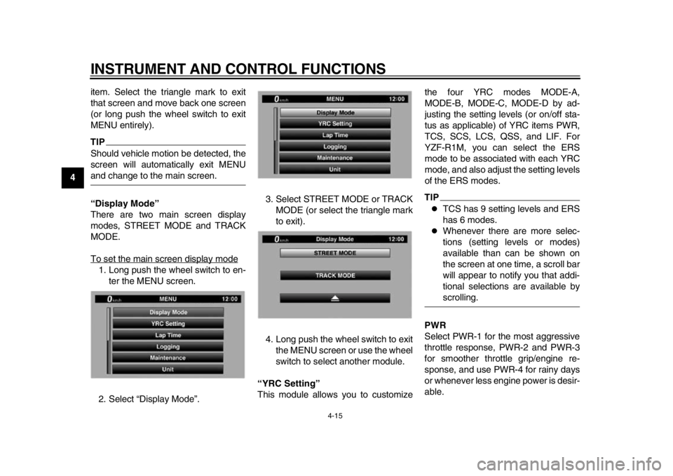
To set the main screen display mode1. Long push the wheel switch to en-
ter the MENU screen.
2. Select “Display Mode”. 3. Select STREET MODE or TRACK
MODE (or select the triangle mark
to exit).
4. Long push the wheel switch to exit the MENU screen or use the wheel
switch to select another module.
“YRC Setting”
This module allows you to customize the four YRC modes MODE-A,
MODE-B, MODE-C, MODE-D by ad-
justing the setting levels (or on/off sta-
tus as applicable) of YRC items PWR,
TCS, SCS, LCS, QSS, and LIF. For
YZF-R1M, you can select the ERS
mode to be associated with each YRC
mode, and also adjust the setting levels
of the ERS modes.
TIP
TCS has 9 setting levels and ERS
has 6 modes.
Whenever there are more selec-
tions (setting levels or modes)
available than can be shown on
the screen at one time, a scroll bar
will appear to notify you that addi-
tional selections are available byscrolling.
PWR
Select PWR-1 for the most aggressive
throttle response, PWR-2 and PWR-3
for smoother throttle grip/engine re-
sponse, and use PWR-4 for rainy days
or whenever less engine power is desir-
able.
2CR-9-E0_1.book 15 ページ 2015年1月5日 月曜日 午前11時54分
Page 51 of 126

INSTRUMENT AND CONTROL FUNCTIONS
4-32
1
2
345
6
7
8
9
10
11
12
Regarding variable UBS, operating the
brake lever will generate corresponding
brake pressure at the front brake and to
a variable degree, the rear brake. The amount of rear wheel braking force to
be applied by the UBS is based on ve-
hicle attitude and lean angle. However,
operating only the brake pedal will not
generate any brake pressure at the
front brake.
For full braking performance, apply
both the brake lever and brake pedal si-
multaneously.
When both the brake lever and the
brake pedal are applied simultaneous-
ly, the UBS will control the distribution
of braking force between the two
wheels.
TIP
The UBS does not function until
the vehicle starts moving.
After coming to a stop while apply-
ing the brake lever, the UBS is still
enabled. As further squeezing of
the brake lever will not increase
the braking power of the rear
brake, apply the rear brake should
further braking power be neces-
sary (such as when parking on a
slope).
The UBS disables after the brake
lever is released.
When the vehicle starts moving,
the UBS is re-enabled.
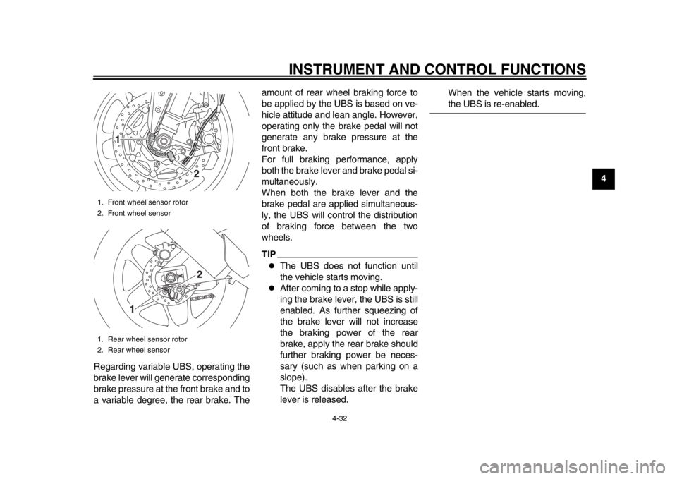
1. Front wheel sensor rotor
2. Front wheel sensor
1. Rear wheel sensor rotor
2. Rear wheel sensor
1
22
1
2CR-9-E0_1.book 32 ページ 2015年1月5日 月曜日 午前11時54分
Page 59 of 126

INSTRUMENT AND CONTROL FUNCTIONS
4-40
1
2
345
6
7
8
9
10
11
12
ing, turn the adjusting bolt on each fork
leg in direction (a). To decrease the re-
bound damping force and thereby soft-
en the rebound damping, turn the
adjusting bolt on each fork leg in direc-
tion (b).
Compression damping force
To increase the compression damping force and thereby harden the compres-
sion damping, turn the adjusting bolt on
each fork leg in direction (a). To de-
crease the compression damping force
and thereby soften the compression
damping, turn the adjusting bolt on
each fork leg in direction (b).
TIPAlthough the total number of clicks of a
damping force adjusting mechanism
may not exactly match the above spec-
ifications due to small differences in
production, the actual number of clicks
always represents the entire adjusting
range. To obtain a precise adjustment,
it would be advisable to check the num-
ber of clicks of each damping force ad-
justing mechanism and to modify thespecifications as necessary.
For YZF-R1M:
This model is is equipped with ÖHLINS
electronic racing suspension.
The compression and rebound damp-
ing forces are electronically adjusted.
(See ERS on page 4-18.)
Spring preload
The spring preload adjustment is per-
formed manually.
1. Turn the vehicle off.
2. Slide the rubber cover back at each coupler.
3. Remove the coupler on each front fork. NOTICE: To prevent dam-
1. Rebound damping force adjusting boltRebound damping setting:
Minimum (soft):
14 click(s) in direction (b)*
Standard: 7 click(s) in direction (b)*
Maximum (hard): 0 click(s) in direction (b)*
* With the adjusting bolt fully turned in
direction (a)
1
(a) (b)
1. Compression damping force adjusting boltCompression damping setting:
Minimum (soft):
23 click(s) in direction (b)*
Standard: 17 click(s) in direction (b)*
Maximum (hard): 0 click(s) in direction (b)*
* With the adjusting bolt fully turned in
direction (a)
1
(a) (b)
2CR-9-E0_1.book 40 ページ 2015年1月5日 月曜日 午前11時54分
Page 64 of 126

INSTRUMENT AND CONTROL FUNCTIONS
4-45
1
2
34
5
6
7
8
9
10
11
12
EAU67050
EXUP systemThis model is equipped with Yamaha’s
EXUP (EXhaust Ultimate Power valve)
system. This system boosts engine
power by means of a valve that controls
exhaust flow within the exhaust cham-
ber.NOTICE
ECA15611
The EXUP system has been set and
extensively tested at the Yamaha
factory. Changing these settings
without sufficient technical knowl-
edge may result in poor perfor-mance of or damage to the engine.
EAU15306
SidestandThe sidestand is located on the left side
of the frame. Raise the sidestand or
lower it with your foot while holding the
vehicle upright.TIPThe built-in sidestand switch is part of
the ignition circuit cut-off system, which
cuts the ignition in certain situations.
(See the following section for an expla-
nation of the ignition circuit cut-off sys-tem.)
WARNING
EWA10242
The vehicle must not be ridden with
the sidestand down, or if the sides-
tand cannot be properly moved up
(or does not stay up), otherwise the
sidestand could contact the ground
and distract the operator, resulting
in a possible loss of control.
Yamaha’s ignition circuit cut-off
system has been designed to assist
the operator in fulfilling the respon-
sibility of raising the sidestand be-
fore starting off. Therefore, check
this system regularly and have a Yamaha dealer repair it if it does not
function properly.
2CR-9-E0_1.book 45 ページ 2015年1月5日 月曜日 午前11時54分
Page 72 of 126

OPERATION AND IMPORTANT RIDING POINTS
6-2
1
2
3
4
56
7
8
9
10
11
12 km/h (6 mi/h).
The oil pressure and coolant tem-
perature warning light should
come on again after going off brief-
ly, and then remain on until the en-
gine is started.
NOTICE
ECA22510
If a warning or indicator light does
not work as described above, see
page 4-6 for the corresponding
warning and indicator light circuitcheck.
2. Shift the transmission into the neu- tral position. The neutral indicator
light should come on. If not, ask a
Yamaha dealer to check the elec-
trical circuit.
3. Start the engine by pushing the start switch.
If the engine does not start within 5
seconds of pressing the start
switch, wait 10 seconds before
pressing the switch again to allow
the battery voltage to restore.NOTICE
ECA11043
For maximum engine life, never ac- celerate hard when the engine is
cold!
EAU67080
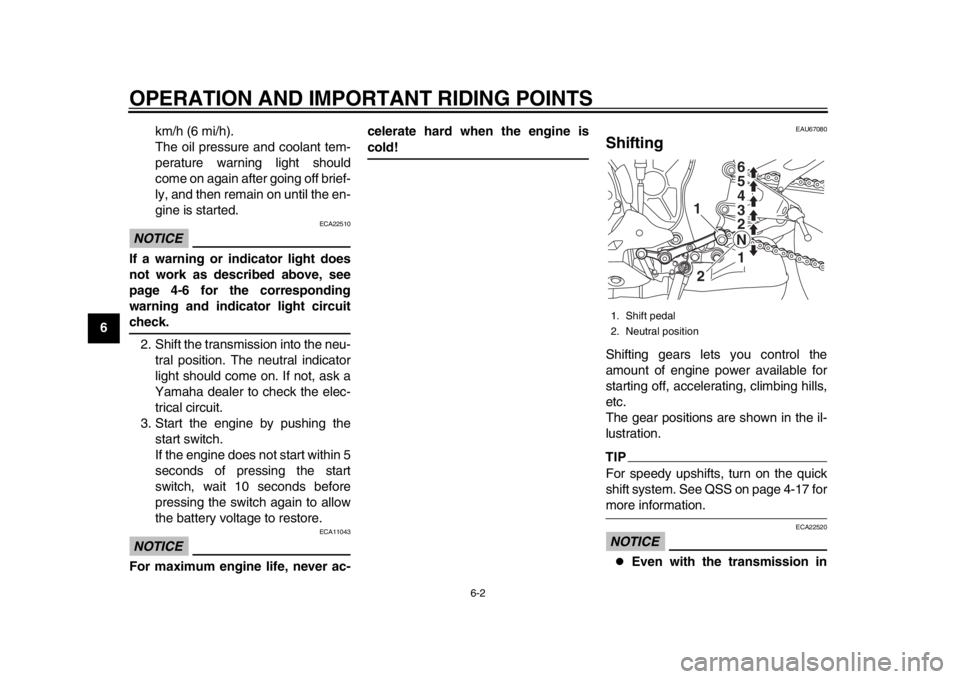
ShiftingShifting gears lets you control the
amount of engine power available for
starting off, accelerating, climbing hills,
etc.
The gear positions are shown in the il-
lustration.TIPFor speedy upshifts, turn on the quick
shift system. See QSS on page 4-17 formore information.NOTICE
ECA22520
Even with the transmission in
1. Shift pedal
2. Neutral position
1
1
2
2 3 4
5 6
N
2CR-9-E0_1.book 2 ページ 2015年1月5日 月曜日 午前11時54分
Page 102 of 126

PERIODIC MAINTENANCE AND ADJUSTMENT
7-27
1
2
3
4
5
67
8
9
10
11
12
EAU23026
Cleaning and l ubricating the
drive chainThe drive chain must be cleaned and
lubricated at the intervals specified in
the periodic maintenance and lubrica-
tion chart, otherwise it will quickly wear
out, especially when riding in dusty or
wet areas. Service the drive chain as
follows.NOTICE
ECA10584
The drive chain must be lubricated
after washing the motorcycle, ridingin the rain or riding in wet areas.
1. Clean the drive chain with kero- sene and a small soft brush.
NOTICE: To prevent damaging
the O-rings, do not clean the
drive chain with steam cleaners,
high-pressure washers or inap-
propriate solvents.
[ECA11122]
2. Wipe the drive chain dry.
3. Thoroughly lubricate the drive chain with a special O-ring chain
lubricant. NOTICE: Do not use
engine oil or any other lubri-
cants for the drive chain, as they may contain substances that
could damage the O-rings.
[ECA11112]
EAU23098
Checking and lubricating the
cablesThe operation of all control cables and
the condition of the cables should be
checked before each ride, and the ca-
bles and cable ends should be lubricat-
ed if necessary. If a cable is damaged
or does not move smoothly, have a
Yamaha dealer check or replace it.
WARNING! Damage to the outer
housing of cables may result in in-
ternal rusting and cause interfer-
ence with cable movement. Replace
damaged cables as soon as possi-
ble to prevent unsafe condi-
tions.
[EWA10712]
Recommended lubricant:
Yamaha cable lubricant or other suit-
able cable lubricant
2CR-9-E0_1.book 27 ページ 2015年1月5日 月曜日 午前11時54分
Page 114 of 126

8-1
1
2
3
4
5
6
78
9
10
11
12
MOTORCYCLE CARE AND STORAGE
EAU37834
Matte color cautionNOTICE
ECA15193
Some models are equipped with
matte colored finished parts. Be
sure to consult a Yamaha dealer for
advice on what products to use be-
fore cleaning the vehicle. Using a
brush, harsh chemical products or
cleaning compounds when cleaning
these parts will scratch or damage
their surface. Wax also should not
be applied to any matte colored fin-ished parts.
EAU67140
CareWhile the open design of a motorcycle
reveals the attractiveness of the tech-
nology, it also makes it more vulnera-
ble. Rust and corrosion can develop
even if high-quality components are
used. A rusty exhaust pipe may go un-
noticed on a car, however, it detracts
from the overall appearance of a motor-
cycle. Frequent and proper care does
not only comply with the terms of the
warranty, but it will also keep your mo-
torcycle looking good, extend its life
and optimize its performance.
Before cleaning 1. Cover the muffler outlet with a plastic bag after the engine has
cooled down.
2. Make sure that all caps and covers as well as all electrical couplers
and connectors, including the
spark plug caps, are tightly in-
stalled.
3. Remove extremely stubborn dirt, like oil burnt onto the crankcase,
with a degreasing agent and a
brush, but never apply such prod- ucts onto seals, gaskets, sprock-
ets, the drive chain and wheel
axles. Always rinse the dirt and de-
greaser off with water.
Cleaning
NOTICE
ECA22530
Avoid using strong acidic wheel
cleaners, especially on spoked
or magnesium wheels. If such
products are used on
hard-to-remove dirt, do not
leave the cleaner on the affected
area any longer than instructed.
Also, thoroughly rinse the area
off with water, immediately dry
it, and then apply a corrosion
protection spray.
Improper cleaning can damage
such parts as cowlings and pan-
els, the windshield, the instru-
ment panel and display, wheels,
headlight lenses, plastic or car-
bon fiber parts, etc., and the
mufflers. Use only a soft, clean
cloth or sponge to clean such
parts. However, if such parts
cannot be thoroughly cleaned,
2CR-9-E0_1.book 1 ページ 2015年1月5日 月曜日 午前11時54分