fuel YAMAHA YZF-R1 2016 Owners Manual
[x] Cancel search | Manufacturer: YAMAHA, Model Year: 2016, Model line: YZF-R1, Model: YAMAHA YZF-R1 2016Pages: 128, PDF Size: 9.43 MB
Page 8 of 128
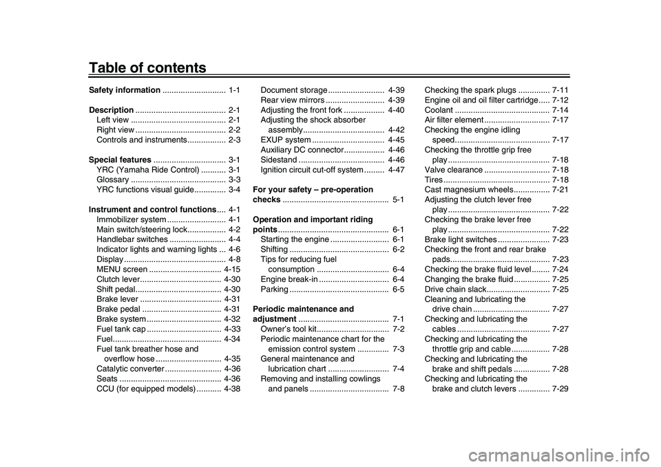
Table of contentsSafety information............................ 1-1
Description ........................................ 2-1
Left view .......................................... 2-1
Right view ........................................ 2-2
Controls and instrument s................. 2-3
Special features ................................ 3-1
YRC (Yamaha Ride Control) ........... 3-1
Glossary .......................................... 3-3
YRC functions visual guide.............. 3-4
Instrument and co ntrol functions.... 4-1
Immobilizer system ....... ................... 4-1
Main switch/steering lock................. 4-2
Handlebar switches ......................... 4-4
Indicator lights and warning lights ... 4-6
Display ............................................. 4-8
MENU screen ................................ 4-15
Clutch lever.................................... 4-30
Shift pedal....... ............................. .. 4-30
Brake lever .................................... 4-31
Brake pedal ................................... 4-31
Brake system ..... ............................ 4-32
Fuel tank cap ................................. 4-33
Fuel................................................ 4-34
Fuel tank breather hose and overflow hose ............................. 4-35
Catalytic converter ......................... 4-36
Seats ............................................. 4-36
CCU (for equipped models) ........... 4-38 Document storage ......................... 4-39
Rear view mirrors .......................... 4-39
Adjusting the front fork .................. 4-40
Adjusting the shock absorber
assembly.................................... 4-42
EXUP system ................................ 4-45
Auxiliary DC connector.................. 4-46
Sidestand ...................................... 4-46
Ignition circuit cut- off system ......... 4-47
For your safety – pre-operation
checks ............................................... 5-1
Operation and important riding
points ................................................. 6-1
Starting the engine .......................... 6-1
Shifting ............................................ 6-2
Tips for reducing fuel consumption ................................ 6-4
Engine break-in ............................... 6-4
Parking ............................................ 6-5
Periodic maintenance and
adjustment ........................................ 7-1
Owner’s tool kit................................ 7-2
Periodic maintenance chart for the emission control system .............. 7-3
General maintenance and
lubrication chart ........................... 7-4
Removing and installing cowlings and panels ............... .................... 7-8 Checking the spark plugs .............. 7-11
Engine oil and oil filt
er cartridge..... 7-12
Coolant .......................................... 7-14
Air filter element ............................. 7-17
Checking the engine idling speed............ ............................ .. 7-17
Checking the throttle grip free play ............................................. 7-18
Valve clearance ............................. 7-18
Tires ............................................... 7-18
Cast magnesium wheels ................ 7-21
Adjusting the clutch lever free play ............................................. 7-22
Checking the brake lever free
play ............................................. 7-22
Brake light switches ....................... 7-23
Checking the front and rear brake
pads............................................ 7-23
Checking the brake fluid level ........ 7-24
Changing the brake fluid ................ 7-25
Drive chain slack............................ 7-25
Cleaning and lubricating the drive chain .................................. 7-27
Checking and lubricating the cables ......................................... 7-27
Checking and lubricating the throttle grip and cable ................. 7-28
Checking and lubricating the
brake and shift pedals ................ 7-28
Checking and lubricating the brake and clutch levers .............. 7-292CR-9-E1.book 1 ページ 2015年8月20日 木曜日 午後4時46分
Page 14 of 128
Safety information
1-5
1
2
3
4
5
6
7
8
9
10
11
12
Check that the fuel cock (if
equipped) is in the “OFF” position
and that there are no fuel leaks.
Point the front wheel straight
ahead on the trailer or in the truck
bed, and choke it in a rail to pre-
vent movement.
Shift the transmission in gear (for
models with a manual transmis-
sion).
Secure the motorcycle with
tie-downs or suitable straps that
are attached to solid parts of the
motorcycle, such as the frame or
upper front fork triple clamp (and
not, for example, to rubber-mount-
ed handlebars or turn signals, or
parts that could break). Choose
the location for the straps carefully
so the straps will not rub against
painted surfaces during transport.
The suspension should be com-
pressed somewhat by the
tie-downs, if possible, so that the
motorcycle will not bounce exces-
sively during transport.
2CR-9-E1.book 5 ページ 2015年8月20日 木曜日 午後4時46分
Page 15 of 128

2-1
123
4
5
6
7
8
9
10
11
12
Description
EAU10411
Left view
1 3
4 5,6
10 89
2
11
7
1. Fuse box (page 7-33)
2. ERS coupler (YZF-R1M) (page 4-40)
3. Spring preload adjusting bo lt (YZF-R1M) (page 4-40)
4. Fuel tank cap (page 4-33)
5. Battery (page 7-31)
6. Main fuse (page 7-33)
7. Drive chain puller (page 7-25)
8. Spring preload adjusting ring (page 4-42) 9. Shift pedal (page 4-30)
10.Engine oil level check window (page 7-12)
11.Engine oil filter cartridge (page 7-12)
2CR-9-E1.book 1 ページ 2015年8月20日 木曜日 午後4時46分
Page 27 of 128
Instrument and control functions
4-6
1
2
345
6
7
8
9
10
11
12
scroll up/left or increase a setting value.
Rotate down
- rotate the wheel down-
ward to scroll down/right or decrease a
setting value.
Short push - briefly press the switch in-
ward to make and confirm selections.
Long push - press the switch inward
for one second to reset an information
display item or to access and exit the
MENU screen.
TIP
See page 4-8 for more information
on the main screen and its func-
tions.
See page 4-15 for more informa-
tion on the MENU screen and howto make setting changes.
EAU49398
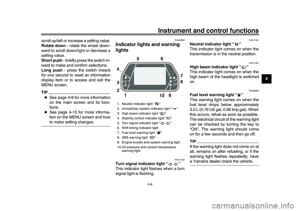
Indicator lights and warning
lights
EAU11022
Turn signal indicator light “ ”
This indicator light flashes when a turn
signal light is flashing.
EAU11061
Neutral indicator light “ ”
This indicator light comes on when the
transmission is in the neutral position.
EAU11081
High beam indicator light “ ”
This indicator light comes on when the
high beam of the headlight is switched
on.
EAU66890
Fuel level warning light “ ”
This warning light comes on when the
fuel level drops below approximately
3.0 L (0.79 US gal, 0.66 Imp.gal). When
this occurs, refuel as soon as possible.
The electrical circuit of the warning light
can be checked by turning the key to
“ON”. The warning light should come
on for a few seconds and then go off.TIPIf the warning light does not come on at
all, remains on after refueling, or if the
warning light flashes repeatedly, havea Yamaha dealer check the vehicle.
1. Neutral indicator light “ ”
2. Immobilizer system indicator light “ ”
3. High beam indicator light “ ”
4. Stability control indicator light “SC”
5. Turn signal indicator light “ ”
6. Shift timing indicator light
7. Fuel level warning light “ ”
8. ABS warning light “ ”
9. Engine trouble and system warning light
10.Oil pressure and coolant temperature warning light
11 09
2 3 4 56
7
8
ABS
2CR-9-E1.book 6 ページ 2015年8月20日 木曜日 午後4時46分
Page 31 of 128

Instrument and control functions
4-10
1
2
345
6
7
8
9
10
11
12
dent.
Speedometer
The speedometer shows the vehicle’s
traveling speed.
For certain markets, the display can be
switched between kilometers and
miles. (See “Unit” on page 4-22.)
Tachometer
The tachometer shows the engine
speed, as measured by the rotational
velocity of the crankshaft, in revolutions
per minute (r/min). When the vehicle is
first powered on, the tachometer will
sweep across the r/min range and then
return to zero.TIP
In TRACK MODE, the tachometer
starts at 8000 r/min.
In STREET MODE, the tachome-
ter can be color-adjusted and has
a revolution peak hold indicatorwhich can be turned on or off.
NOTICE
ECA10032
Do not operate the engine in the ta- chometer red zone.
Red zone: 14000 r/min and above
Information display
This section of the main screen is used
to show additional riding related infor-
mation such as air and coolant temper-
ature readings, tripmeters, and fuel
consumption statistics. The information
display items can be set into four
groups via the MENU screen.
The information display items are:
A.TEMP: air temperature
C.TEMP: coolant temperature
TRIP-1: tripmeter 1
TRIP-2: tripmeter 2
F-TRIP: fuel tripmeter
ODO: odometer
FUEL CON: the amount of fuel con-
sumed
FUEL AVG: average fuel consumption
CRNT FUEL: current fuel consumptionTIP
ODO will lock at 999999 and can-
not be reset.
TRIP-1 and TRIP-2 will reset and
continue counting after 9999.9 has
been reached.
When the fuel tank reserve level
has been reached, F-TRIP ap-
pears automatically and begins re-
cording distance traveled from that
point.
After refueling and traveling some
distance, F-TRIP will automatically
disappear.
See “Unit” on page 4-22 to change
the fuel consumption units.
In TRACK MODE, information dis-
play items FASTEST (fastest lap
time) and AVERAGE (average laptime) are also available.
TRIP-1, TRIP-2, F-TRIP, FUEL CON,
and FUEL AVE items can be individual-
ly reset.
To reset information display items
1. Use the wheel switch to scroll through the display items until the
item you want to reset appears.
2. Short push the wheel switch and the item will flash for five seconds.
(For STREET MODE, if both items
are resettable items, the top item
will flash first. Scroll down to select
the bottom item.)
2CR-9-E1.book 10 ページ 2015年8月20日 木曜日 午後4時46分
Page 36 of 128

Instrument and control functions
4-15
1
2
34
5
6
7
8
9
10
11
12
EAU67631
MENU screenThe MENU screen contains the follow-
ing setting modules. Select a module to
make related setting changes. Al-
though some settings can be changed
or reset via the main screen, the MENU
screen offers access to all display and
control settings. MENU access and operation
The following wheel switch operations
are common operations for accessing,
selecting, and moving within the MENU
screen and its modules.
Long push - press and hold the wheel
switch for one second to access the
MENU screen or exit MENU entirely.
Select - rotate the wheel switch up or
down to highlight the desired module or
setting item and then short push the
wheel switch (briefly press the wheel
switch inward) to confirm the selection.
Triangle mark
- certain setting screens
have an upward pointing triangle mark item. Select the triangle mark to exit
that screen and move back one screen
(or long push the wheel switch to exit
MENU entirely).
TIPShould vehicle motion be detected, the
screen will automatically exit MENUand change to the main screen.
“Display Mode”
There are two main screen display
modes, STREET MODE and TRACK
MODE.
To set the main screen display mode1. Long push the wheel switch to en-
ter the MENU screen.
2. Select “Display Mode”.
Display Description
Display Mode Switch the main screen
display between street and
track modes.
YRC Setting Adjust YRC settings (all
models) and ERS settings
(YZF-R1M).
Lap Time View and reset lap times.
Logging Turn vehicle information
logging function on/off
(CCU-equipped models).
Maintenance View and reset three
maintenance item
intervals.
Unit Set fuel consumption and
distance units.
Wallpaper Set background colors.
Shift Indicator Turn the shift indicator on/
off and adjust tachometer
settings.
Display Setting Set the multi-function
display window items.
Brightness Adjust screen brightness. Clock Adjust the clock.
All Reset Return all settings to
factory default settings.
2CR-9-E1.book 15 ページ 2015年8月20日 木曜日 午後4時46分
Page 43 of 128
Instrument and control functions
4-22
1
2
345
6
7
8
9
10
11
12
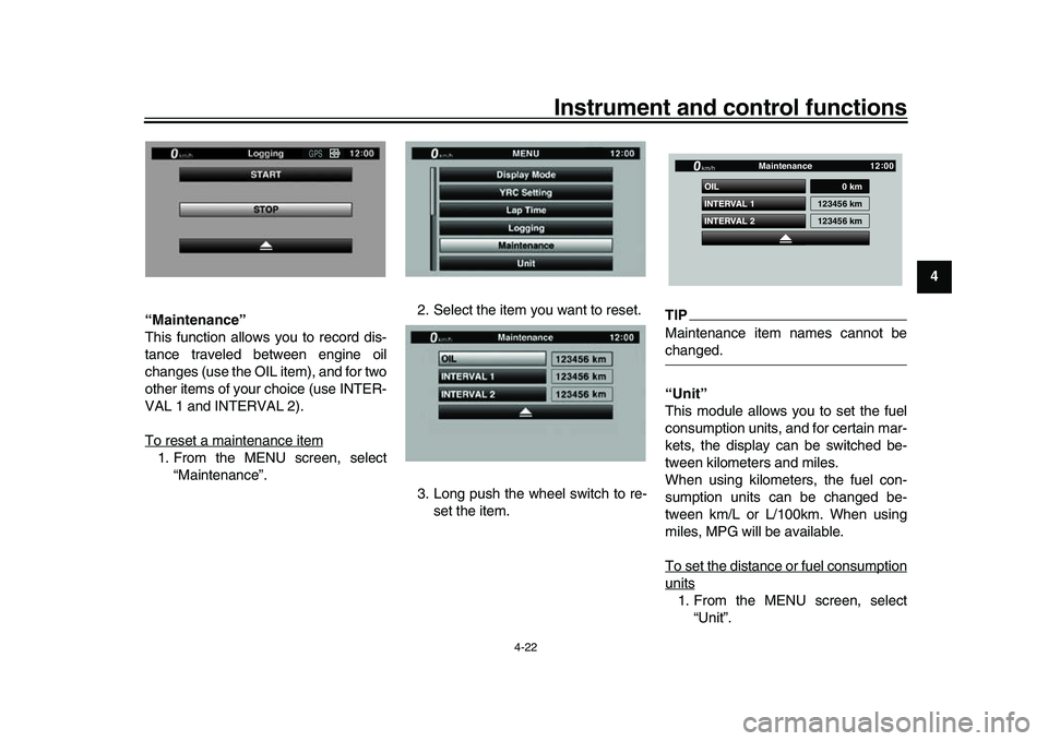
“Maintenance”
This function allows you to record dis-
tance traveled between engine oil
changes (use the OIL item), and for two
other items of your choice (use INTER-
VAL 1 and INTERVAL 2).
To reset a maintenance item
1. From the MENU screen, select
“Maintenance”. 2. Select the item you want to reset.
3. Long push the wheel switch to re-
set the item.
TIPMaintenance item names cannot bechanged.
“Unit”
This module allows you to set the fuel
consumption units, and for certain mar-
kets, the display can be switched be-
tween kilometers and miles.
When using kilometers, the fuel con-
sumption units can be changed be-
tween km/L or L/100km. When using
miles, MPG will be available.
To set the distance or fuel consumptionunits1. From the MENU screen, select“Unit”.
GPS
INTERVAL 2 OIL
INTERVAL 1
0 km
123456 km
123456 km
Maintenance
km/h
GPS
12 :
00
2CR-9-E1.book 22 ページ 2015年8月20日 木曜日 午後4時46分
Page 49 of 128
Instrument and control functions
4-28
1
2
345
6
7
8
9
10
11
12
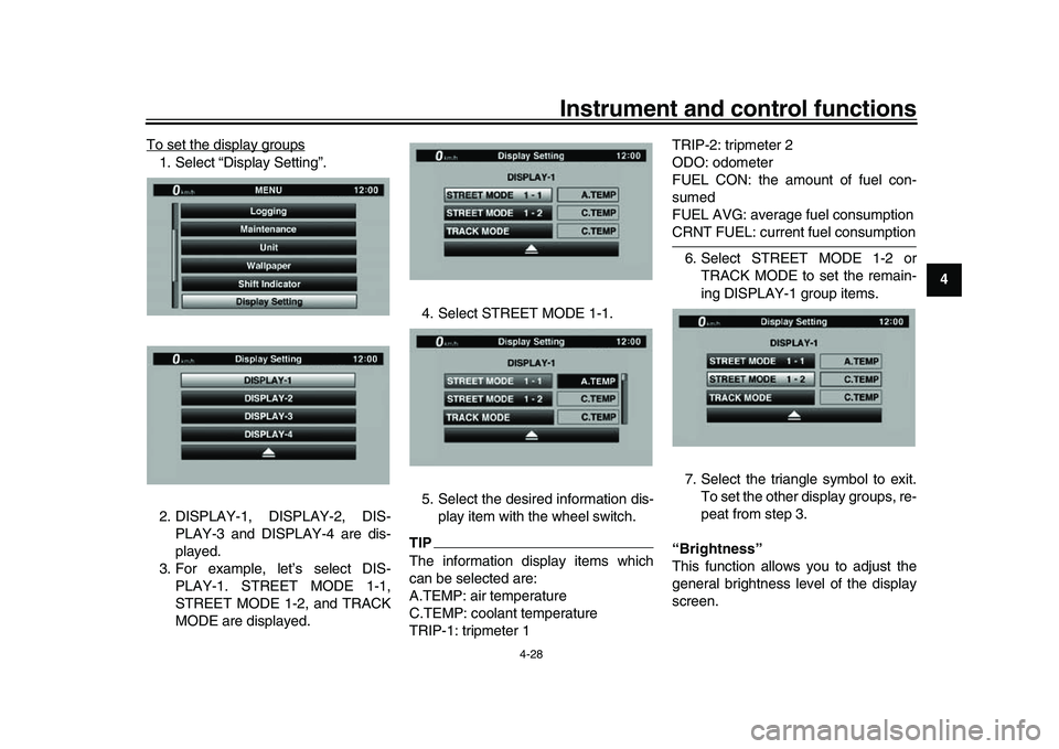
To set the display groups
1. Select “Display Setting”.
2. DISPLAY-1, DISPLAY-2, DIS-
PLAY-3 and DISPLAY-4 are dis-
played.
3. For example, let’s select DIS- PLAY-1. STREET MODE 1-1,
STREET MODE 1-2, and TRACK
MODE are displayed. 4. Select STREET MODE 1-1.
5. Select the desired information dis-
play item with the wheel switch.
TIPThe information display items which
can be selected are:
A.TEMP: air temperature
C.TEMP: coolant temperature
TRIP-1: tripmeter 1 TRIP-2: tripmeter 2
ODO: odometer
FUEL CON: the amount of fuel con-
sumed
FUEL AVG: average fuel consumption
CRNT FUEL: current fuel consumption
6. Select STREET MODE 1-2 or TRACK MODE to set the remain-
ing DISPLAY-1 group items.
7. Select the triangle symbol to exit. To set the other display groups, re-
peat from step 3.
“Brightness”
This function allows you to adjust the
general brightness level of the display
screen.
2CR-9-E1.book 28 ページ 2015年8月20日 木曜日 午後4時46分
Page 54 of 128

Instrument and control functions
4-33
1
2
34
5
6
7
8
9
10
11
12 amount of rear wheel braking force to
be applied by the UBS is based on ve-
hicle attitude and lean angle. However,
operating only the brake pedal will not
generate any brake pressure at the
front brake.
For full braking performance, apply
both the brake lever and brake pedal si-
multaneously.
When both the brake lever and the
brake pedal are applied simultaneous-
ly, the UBS will control the distribution
of braking force between the two
wheels.
TIP
The UBS does not function until
the vehicle starts moving.
After coming to a stop while apply-
ing the brake lever, the UBS is still
enabled. As further squeezing of
the brake lever will not increase
the braking power of the rear
brake, apply the rear brake should
further braking power be neces-
sary (such as when parking on a
slope).
The UBS disables after the brake
lever is released. When the vehicle starts moving,
the UBS is re-enabled.
EAU13075
Fuel tank capTo open the fuel tank cap
Open the fuel tank cap lock cover, in-
sert the key into the lock, and then turn
it 1/4 turn clockwise. The lock will be re-
leased and the fuel tank cap can be
opened.
To close the fuel tank cap
1. Push the fuel tank cap into position with the key inserted in the lock.
2. Turn the key counterclockwise to the original position, remove it, and
then close the lock cover.1. Fuel tank cap lock cover
2. Unlock.
1
2
2CR-9-E1.book 33 ページ 2015年8月20日 木曜日 午後4時46分
Page 55 of 128
Instrument and control functions
4-34
1
2
345
6
7
8
9
10
11
12
TIPThe fuel tank cap cannot be closed un-
less the key is in the lock. In addition,
the key cannot be removed if the cap isnot properly closed and locked.
WARNING
EWA11092
Make sure that the fuel tank cap is
properly closed after filling fuel.Leaking fuel is a fire hazard.
EAU13222
FuelMake sure there is sufficient gasoline in
the tank.
WARNING
EWA10882
Gasoline and gasoline vapors are
extremely flammable. To avoid fires
and explosions and to reduce the
risk of injury when refueling, followthese instructions. 1. Before refueling, turn off the en- gine and be sure that no one is sit-
ting on the vehicle. Never refuel
while smoking, or while in the vi-
cinity of sparks, open flames, or
other sources of ignition such as
the pilot lights of water heaters and
clothes dryers.
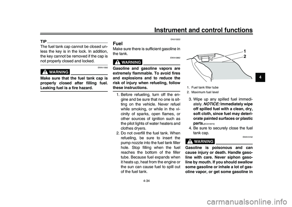
2. Do not overfill the fuel tank. When refueling, be sure to insert the
pump nozzle into the fuel tank filler
hole. Stop filling when the fuel
reaches the bottom of the filler
tube. Because fuel expands when
it heats up, heat from the engine or
the sun can cause fuel to spill out
of the fuel tank. 3. Wipe up any spilled fuel immedi-
ately. NOTICE: Immediately wipe
off spilled fuel with a clean, dry,
soft cloth, since fuel may deteri-
orate painted surfaces or plastic
parts.
[ECA10072]
4. Be sure to securely close the fuel tank cap.
WARNING
EWA15152
Gasoline is poisonous and can
cause injury or death. Handle gaso-
line with care. Never siphon gaso-
line by mouth. If you should swallow
some gasoline or inhale a lot of gas-
oline vapor, or get some gasoline in1. Fuel tank filler tube
2. Maximum fuel level
1
2
2CR-9-E1.book 34 ページ 2015年8月20日 木曜日 午後4時46分