check engine YAMAHA YZF-R1 2017 Owner's Manual
[x] Cancel search | Manufacturer: YAMAHA, Model Year: 2017, Model line: YZF-R1, Model: YAMAHA YZF-R1 2017Pages: 130, PDF Size: 9.99 MB
Page 94 of 130
Periodic maintenance and adjustment
7-18
1
2
3
4
5
67
8
9
10
11
12 12. Install the coolant reservoir cap.
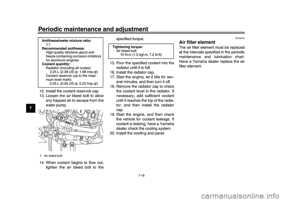
13. Loosen the air bleed bolt to allow
any trapped air to escape from the
water pump.
14. When coolant begins to flow out, tighten the air bleed bolt to the specified torque.
15. Pour the specified coolant into the radiator until it is full.
16. Install the radiator cap.
17. Start the engine, let it idle for sev-
eral minutes, and then turn it off.
18. Remove the radiator cap to check the coolant level in the radiator. If
necessary, add sufficient coolant
until it reaches the top of the radia-
tor, and then install the radiator
cap.
19. Start the engine, and then check the vehicle for coolant leakage. If
coolant is leaking, have a Yamaha
dealer check the cooling system.
20. Install the cowling and panel.
EAU36765
Air filter elementThe air filter element must be replaced
at the intervals specified in the periodic
maintenance and lubrication chart.
Have a Yamaha dealer replace the air
filter element.
Antifreeze/water mixture ratio: 1:1
Recommended antifreeze: High-quality ethylene glycol anti-
freeze containing corrosion inhibitors
for aluminum engines
Coolant quantity:
Radiator (including all routes):2.25 L (2.38 US qt, 1.98 Imp.qt)
Coolant reservoir (up to the maxi-
mum level mark):
0.25 L (0.26 US qt, 0.22 Imp.qt)1. Air bleed bolt
1
Tightening torque: Air bleed bolt:10 N·m (1.0 kgf·m, 7.2 lb·ft)
BX4-9-E0.book 18 ページ 2016年12月1日 木曜日 午後8時7分
Page 95 of 130

Periodic maintenance and adjustment7-19
1
2
3
4
5
678
9
10
11
12
EAU44735
Checking the engine idling
speedCheck the engine idling speed and, if
necessary, have it corrected by a
Yamaha dealer.
EAU21386
Checking the throttle grip free
playMeasure the throttle grip free play as
shown.
Periodically check the throttle grip free
play and, if necessary, have a Yamaha
dealer adjust it.
EAU21402
Valve clearanceThe valve clearance changes with use,
resulting in improper air-fuel mixture
and/or engine noise. To prevent this
from occurring, the valve clearance
must be adjusted by a Yamaha dealer
at the intervals specified in the periodic
maintenance and lubrication chart.
Engine idling speed: 1200–1400 r/min
1. Throttle grip free playThrottle grip free play:3.0–5.0 mm (0.12–0.20 in)
1
BX4-9-E0.book 19 ページ 2016年12月1日 木曜日 午後8時7分
Page 103 of 130
Periodic maintenance and adjustment7-27
1
2
3
4
5
678
9
10
11
12
EAU22762
Drive chain slackThe drive chain slack should be
checked before each ride and adjusted
if necessary.
EAU74251
To check the drive chain slack 1. Place the motorcycle on the sides- tand.TIPWhen checking and adjusting the drive
chain slack, there should be no weighton the motorcycle.
2. Shift the transmission into the neu- tral position.
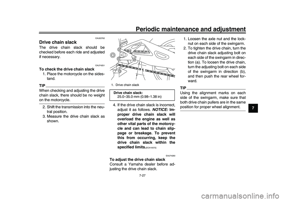
3. Measure the drive chain slack as shown. 4. If the drive chain slack is incorrect,
adjust it as follows. NOTICE: Im-
proper drive chain slack will
overload the engine as well as
other vital parts of the motorcy-
cle and can lead to chain slip-
page or breakage. To prevent
this from occurring, keep the
drive chain slack within the
specified limits.
[ECA10572]
EAU74260
To adjust the drive chain slack
Consult a Yamaha dealer before ad-
justing the drive chain slack. 1. Loosen the axle nut and the lock-
nut on each side of the swingarm.
2. To tighten the drive chain, turn the drive chain slack adjusting bolt on
each side of the swingarm in direc-
tion (a). To loosen the drive chain,
turn the adjusting bolt on each side
of the swingarm in direction (b),
and then push the rear wheel for-
ward.
TIPUsing the alignment marks on each
side of the swingarm, make sure that
both drive chain pullers are in the sameposition for proper wheel alignment.
1. Drive chain slackDrive chain slack:25.0–35.0 mm (0.98–1.38 in)
1
BX4-9-E0.book 27 ページ 2016年12月1日 木曜日 午後8時7分
Page 109 of 130
Periodic maintenance and adjustment7-33
1
2
3
4
5
678
9
10
11
12
EAU68230
BatteryNOTICE
ECA22960
Use only the specified genuine
YAMAHA battery. Using a different
battery may cause the IMU to fail andthe engine to stall.
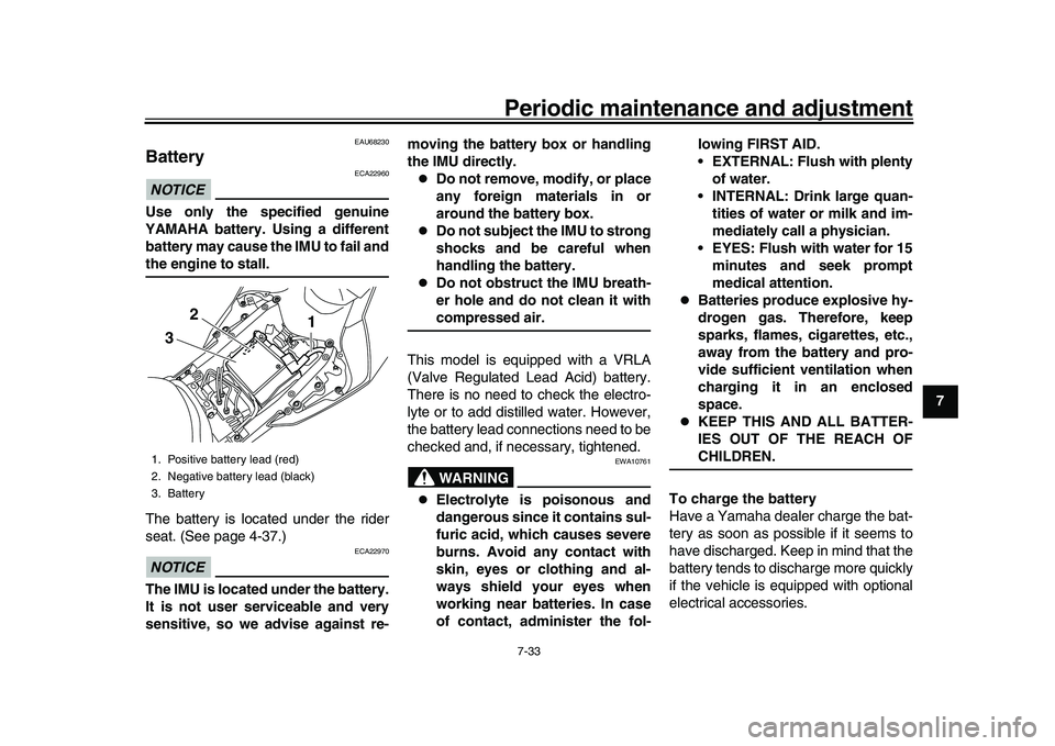
The battery is located under the rider
seat. (See page 4-37.)NOTICE
ECA22970
The IMU is located under the battery.
It is not user serviceable and very
sensitive, so we advise against re- moving the battery box or handling
the IMU directly.
Do not remove, modify, or place
any foreign materials in or
around the battery box.
Do not subject the IMU to strong
shocks and be careful when
handling the battery.
Do not obstruct the IMU breath-
er hole and do not clean it withcompressed air.
This model is equipped with a VRLA
(Valve Regulated Lead Acid) battery.
There is no need to check the electro-
lyte or to add distilled water. However,
the battery lead connections need to be
checked and, if necessary, tightened.WARNING
EWA10761
Electrolyte is poisonous and
dangerous since it contains sul-
furic acid, which causes severe
burns. Avoid any contact with
skin, eyes or clothing and al-
ways shield your eyes when
working near batteries. In case
of contact, administer the fol- lowing FIRST AID.
EXTERNAL: Flush with plenty
of water.
INTERNAL: Drink large quan- tities of water or milk and im-
mediately call a physician.
EYES: Flush with water for 15 minutes and seek prompt
medical attention.
Batteries produce explosive hy-
drogen gas. Therefore, keep
sparks, flames, cigarettes, etc.,
away from the battery and pro-
vide sufficient ventilation when
charging it in an enclosed
space.
KEEP THIS AND ALL BATTER-
IES OUT OF THE REACH OFCHILDREN.
To charge the battery
Have a Yamaha dealer charge the bat-
tery as soon as possi ble if it seems to
have discharged. Keep in mind that the
battery tends to discharge more quickly
if the vehicle is equipped with optional
electrical accessories.
1. Positive battery lead (red)
2. Negative battery lead (black)
3. Battery
1
2
3
BX4-9-E0.book 33 ページ 2016年12月1日 木曜日 午後8時7分
Page 115 of 130
Periodic maintenance and adjustment7-39
1
2
3
4
5
678
9
10
11
12
EAU42505
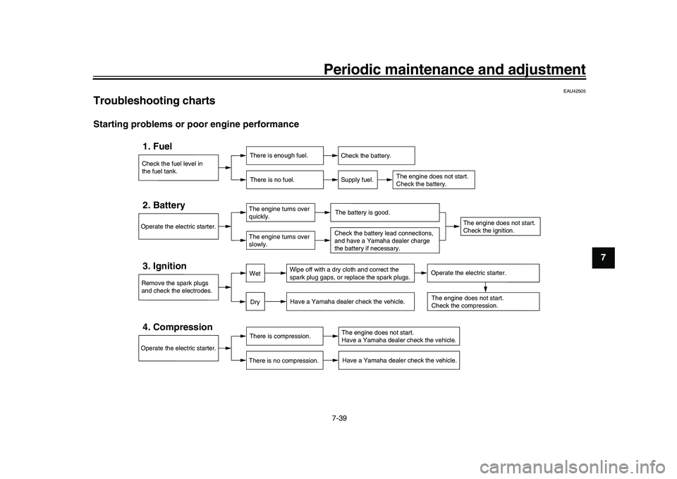
Troubleshooting chartsStarting problems or poor engine performance
Check the fuel level in
the fuel tank.1. Fuel
There is enough fuel.
There is no fuel.
Check the battery.
Supply fuel.
The engine does not start.
Check the battery.
Remove the spark plugs
and check the electrodes.3. Ignition
Wipe off with a dry cloth and correct the
spark plug gaps, or replace the spark plugs.
Have a Yamaha dealer check the vehicle.
Operate the electric starter.4. Compression
There is compression.
There is no compression.
The engine does not start.
Have a Yamaha dealer check the vehicle.Have a Yamaha dealer check the vehicle.
The engine does not start.
Check the compression.
Operate the electric starter.2. Battery
The engine turns over
quickly.
The engine turns over
slowly.
The engine does not start.
Check the ignition.
The battery is good.Check the battery lead connections,
and have a Yamaha dealer charge
the battery if necessary.
DryWet
Operate the electric starter.
BX4-9-E0.book 39 ページ 2016年12月1日 木曜日 午後8時7分
Page 116 of 130

Periodic maintenance and adjustment
7-40
1
2
3
4
5
67
8
9
10
11
12 Engine overheating
WARNING
EWAT1041
Do not remove the radiator cap when the engine and radiator are hot. Scalding hot fluid and steam may be
blown out under pressure, which could cause serious injury. Be sure to wait until the engine has cooled.
Place a thick rag, like a towel, over the radiator cap, and then slowly rotate the cap counterclockwise to the de-
tent to allow any residual pressure to escape. When the hissing sound has stopped, press down on the capwhile turning it counterclockwise, and then remove the cap.
TIPIf coolant is not available, tap water can be temporarily us
ed instead, provided that it is changed to the recommended coolantas soon as possible.
Wait until the
engine has cooled.
Check the coolant level in the
reservoir and radiator.
The coolant level
is OK.The coolant level is low.
Check the cooling system
for leakage.
Have a Yamaha dealer checkand repair the cooling system.Add coolant. (See TIP.)
Start the engine. If the engine overheats again,
have a
Yamaha dealer check
and repair the cooling system.
There is
leakage.
There is
no leakage.
BX4-9-E0.book 40 ページ 2016年12月1日 木曜日 午後8時7分
Page 120 of 130
Motorcycle care and storage
8-4
1
2
3
4
5
6
78
9
10
11
12
EAU26183
StorageShort-term
Always store your motorcycle in a cool,
dry place and, if necessary, protect it
against dust with a porous cover. Be
sure the engine and the exhaust sys-
tem are cool before covering the motor-
cycle.NOTICE
ECA10811
Storing the motorcycle in a
poorly ventilated room or cover-
ing it with a tarp, while it is still
wet, will allow water and humid-
ity to seep in and cause rust.
To prevent corrosion, avoid
damp cellars, stables (because
of the presence of ammonia)
and areas where strong chemi-cals are stored.
Long-term
Before storing your motorcycle for sev-
eral months: 1. Follow all the instructions in the “Care” section of this chapter. 2. Fill up the fuel tank and add fuel
stabilizer (if available) to prevent
the fuel tank from rusting and the
fuel from deteriorating.
3. Perform the following steps to pro- tect the cylinders, piston rings, etc.
from corrosion.
a. Remove the spark plug caps and spark plugs.
b. Pour a teaspoonful of engine oil into each spark plug bore.
c. Install the spark plug caps onto the spark plugs, and then place
the spark plugs on the cylinder
head so that the electrodes are
grounded. (This will limit spark-
ing during the next step.)
d. Turn the engine over several times with the starter. (This will
coat the cylinder walls with oil.)
WARNING! To prevent dam-
age or injury from sparking,
make sure to ground the
spark plug electrodes while
turning the engine
over.
[EWA10952]
e. Remove the spark plug capsfrom the spark plugs, and then
install the spark plugs and the spark plug caps.
4. Lubricate all control cables and the pivoting points of all levers and
pedals as well as of the sidestand/
centerstand.
5. Check and, if necessary, correct the tire air pressure, and then lift
the motorcycle so that both of its
wheels are off the ground. Alterna-
tively, turn the wheels a little every
month in order to prevent the tires
from becoming degraded in one
spot.
6. Cover the muffler outlet with a plastic bag to prevent moisture
from entering it.
7. Remove the battery and fully charge it. Store it in a cool, dry
place and charge it once a month.
Do not store the battery in an ex-
cessively cold or warm place [less
than 0 C (30 F) or more than 30
C (90 F)]. For more information
on storing the battery, see page
7-33.
TIPMake any necessary repairs beforestoring the motorcycle.
BX4-9-E0.book 4 ページ 2016年12月1日 木曜日 午後8時7分
Page 125 of 130

Consumer information
10-2
1
2
3
4
5
6
7
8
91011
12
EAU26521
Model label
The model label is affixed to the frame
under the passenger seat. (See
page 4-37.) Record the information on
this label in the space provided. This in-
formation will be needed when ordering
spare parts from a Yamaha dealer.
EAU69910
Diagnostic connectorThe diagnostic connector is located as
shown.
EAU74701
Vehicle data recordingThis model’s ECU stores certain vehi-
cle data to assist in the diagnosis of
malfunctions and for research and de-
velopment purposes. This data will be
uploaded only when a special Yamaha
diagnostic tool is attached to the vehi-
cle, such as when maintenance checks
or service procedures are performed.
Although the sensors and recorded
data will vary by model, the main data
points are:
Vehicle status and engine perfor-
mance data
Fuel-injection and emission-relat-
ed data
Yamaha will not disclose this data to a
third party except:
With the consent of the vehicle
owner
Where obligated by law
For use by Yamaha in litigation
For general Yamaha-conducted
research purposes when the data
is not related to an individual vehi-
cle nor owner
1. Model label
1
1. Diagnostic connector
1
BX4-9-E0.book 2 ページ 2016年12月1日 木曜日 午後8時7分
Page 126 of 130
11-1
1
2
3
4
5
6
7
8
9
1011
12
IndexAABS warning light.................................... 4-6
Air filter element .................................... 7-18
Auxiliary DC connector ......................... 4-46BBattery................................................... 7-33
Brake and clutch levers, checking and lubricating ........................................... 7-30
Brake and shift pedals, checking and lubricating ........................................... 7-29
Brake fluid, changing ............................ 7-26
Brake fluid level, checking .................... 7-25
Brake lever ............................................ 4-31
Brake lever free play, checking ............. 7-24
Brake light switches .............................. 7-24
Brake pedal ........................................... 4-31
Brake system ........................................ 4-32CCables, checking and lubricating .......... 7-29
Canister................................................. 7-13
Care ........................................................ 8-1
Catalytic converter ................................ 4-36
CCU ...................................................... 4-38
Clutch lever ........................................... 4-30
Clutch lever free play, adjusting ............ 7-23
Coolant.................................................. 7-16
Cowlings and panels, removing and installing................................................ 7-9DData recording, vehicle ......................... 10-2
Diagnostic connector ............................ 10-2
Dimmer switch ........................................ 4-4
Display, main screen............................... 4-9
Display, menu screen ........................... 4-15 Document storage ................................ 4-39
Drive chain, cleaning and lubricating .... 7-28
Drive chain slack .................................. 7-27
EEngine break-in ...................................... 6-3
Engine idling speed, checking .............. 7-19
Engine oil and oil fi
lter cartridge ........... 7-13
Engine serial number............................ 10-1
Engine trouble warning light ................... 4-6
EXUP system ....................................... 4-46FFront and rear brake pads, checking .... 7-25
Front fork, adjusting .............................. 4-40
Front fork, checking .............................. 7-31
Fuel....................................................... 4-34
Fuel consumption, tips for reducing........ 6-3
Fuel level warning light ........................... 4-6
Fuel tank breather hose and overflow hose ................................................... 4-36
Fuel tank cap ........................................ 4-33
Fuses, replacing ................................... 7-34GGlossary ................................................. 3-3HHandlebar switches ................................ 4-3
Hazard switch ......................................... 4-4
High beam indicator light ........................ 4-6
Horn switch ............................................. 4-4IIdentification numbers .......................... 10-1
Ignition circuit cut-off system ................ 4-47
Immobilizer system ................................. 4-1
Immobilizer system indicator light........... 4-7
Indicator lights and warning lights .......... 4-6
MMain switch/steering lock ........................ 4-2
Maintenance and lubrication, periodic..... 7-5
Maintenance, emission control system ... 7-3
Matte color, caution ................................. 8-1
Model label ............................................ 10-2NNeutral indicator light .............................. 4-6OOil pressure and coolant temperature warning light.......................................... 4-8PParking .................................................... 6-4
Part locations .......................................... 2-1
Pass/LAP switch ..................................... 4-4RRear view mirrors .................................. 4-40SSafety information ................................... 1-1
Seats ..................................................... 4-37
Shifting .................................................... 6-2
Shift pedal ............................................. 4-30
Shift timing indicator light ........................ 4-7
Shock absorber assembly, adjusting .... 4-42
Sidestand .............................................. 4-47
Sidestand, checking an d lubricating...... 7-31
Spark plugs, checking ........................... 7-12
Special features ...................................... 3-1
Specifications .......................................... 9-1
Stability control indicator light.................. 4-7
Starting the engine .................................. 6-1
Steering, checking................................. 7-32
Steering damper and suspension
warning light.......................................... 4-8
BX4-9-E0.book 1 ページ 2016年12月1日 木曜日 午後8時7分