ABS YAMAHA YZF-R1 2019 Owners Manual
[x] Cancel search | Manufacturer: YAMAHA, Model Year: 2019, Model line: YZF-R1, Model: YAMAHA YZF-R1 2019Pages: 124, PDF Size: 9.58 MB
Page 6 of 124

Table of contentsSafety information........................... 1-1
Description ....................................... 2-1
Left view ......................................... 2-1
Right view ....................................... 2-2
Controls and instruments................ 2-3
Special features ............................... 3-1
YRC (Yamaha Ride Control) .......... 3-1
Glossary ......................................... 3-4
YRC functions visual guide............. 3-5
Instrument and co ntrol functions... 4-1
Immobilizer system ..... .................... 4-1
Main switch/steering lock................ 4-2
Handlebar switches ........................ 4-3
Indicator lights and warning lights ............................................ 4-5
Display ............................................ 4-8
MENU screen ............................... 4-13
Clutch lever................................... 4-26
Shift pedal..... ............................ .... 4-27
Brake lever ................................... 4-27
Brake pedal .................................. 4-28
Brake system ..... ....................... .... 4-28
Fuel tank cap ................................ 4-30
Fuel............................................... 4-31
Fuel tank overflow hose................ 4-32
Catalytic converter ........................ 4-33
Seats ............................................ 4-34
Document storage ........................ 4-35 Rear view mirrors ......................... 4-36
Adjusting the front fork ................. 4-36
Adjusting the shock absorber
assembly................................... 4-38
EXUP system ............................... 4-40
Auxiliary DC connector................. 4-41
Sidestand ..................................... 4-41
Ignition circuit cut- off system ........ 4-42
For your safety – pre-operation
checks .............................................. 5-1
Operation and important riding
points ................................................ 6-1
Starting the engine ......................... 6-1
Shifting ........................................... 6-2
Tips for reducing fuel consumption ............................... 6-3
Engine break-in .............................. 6-3
Parking ........................................... 6-4
Periodic maintenance and
adjustment ....................................... 7-1
Tool kit............................................ 7-2
Periodic maintenance charts .......... 7-3
Periodic maintenance chart for the emission control system ............. 7-3
General maintenance and
lubrication chart .......................... 7-5
Removing and installing cowlings and panels ............... ................... 7-9 Checking the spark plugs ............ 7-11
Canister ....................................... 7-12
Engine oil and oil filt
er cartridge... 7-12
Why Yamalube ............................ 7-16
Coolant ........................................ 7-16
Air filter element ........................... 7-17
Checking the engine idling speed............ ............................ 7-18
Checking the throttle grip free play ........................................... 7-18
Valve clearance ........................... 7-18
Tires ............................................. 7-19
Cast magnesium wheels.............. 7-21
Adjusting the clutch lever free
play ........................................... 7-22
Checking the brake lever free play ........................................... 7-23
Brake light switches ..................... 7-23
Checking the front and rear brake pads................................ 7-24
Checking the brake fluid level ...... 7-24
Changing the brake fluid .............. 7-25
Drive chain slack.......................... 7-26
Cleaning and lubricating the drive chain ................................ 7-27
Checking and lubricating the cables ....................................... 7-28
Checking and lubricating the
throttle grip and cable ............... 7-28
Checking and lubricating the brake and shift pedals .............. 7-28BX4-9-E2.book 1 ページ 2018年9月6日 木曜日 午後4時39分
Page 19 of 124

Special features
3-4
1
234
5
6
7
8
9
10
11
12
EAU85770
GlossaryABS - Anti-lock Brake System
ABS ECU - Anti-lock Brake System
Electronic Control Unit
ECU - Engine Control Unit
IMU - Inertial Measurement Unit
LCS - Launch Control System
LIF - Lift Control System
PWR - Power delivery mode
QS - Quick Shift
QSS - Quick Shift System
SC - Stability Control
SCS - Slide Control System
TCS - Traction Control System
UBS - Unified Brake System
YRC - Yamaha Ride Control
BX4-9-E2.book 4 ページ 2018年9月6日 木曜日 午後4時39分
Page 25 of 124

Instrument and control functions
4-5
1
2
345
6
7
8
9
10
11
12
When TCS has been turned off,
the SCS, LCS, and LIF systems
are also turned off for all YRC
modes.
See “YRC Setting” on page 4-14
for more information on how to
customize YRC modes and adjustYRC item setting levels.
EAU66100
Wheel switch “ ”
When the main screen is set to
STREET MODE, use the wheel switch
to scroll and reset the information dis-
play items.
When the main screen is set to TRACK
MODE, use the wheel switch to scroll
and reset the information display items
and to activate the lap timer.
When the display has been changed to
the MENU screen, use the wheel
switch to navigate the setting modules
and make setting changes.
Operate the wheel switch as follows.
Rotate up - rotate the wheel upward to
scroll up/left or increase a setting value.
Rotate down - rotate the wheel down-
ward to scroll down/right or decrease a
setting value. Short push
- briefly press the switch in-
ward to make and confirm selections.
Long push - press the switch inward
for one second to reset an information
display item or to access and exit the
MENU screen.
TIP
See page 4-8 for more information
on the main screen and its func-
tions.
See page 4-13 for more informa-
tion on the MENU screen and howto make setting changes.
EAU4939G
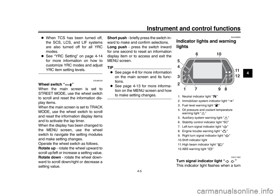
Indicator ligh ts and warning
lights
EAU11022
Turn signal indicator light “ ”
This indicator light flashes when a turn1. Neutral indicator light “ ”
2. Immobilizer system indicator light “ ”
3. Fuel level warning light “ ”
4. Oil pressure and coolant temperature warning light “ ”
5. Auxiliary system warning light “ ”
6. Stability control indicator light “SC”
7. Left turn signal indicator light “ ”
8. Engine trouble warning light “ ”
9. Right turn signal indicator light “ ”
10.Shift indicator light
11.High beam indicator light “ ”
12.ABS warning light “ ”
19 8
2 3 4 610
11
12
7
5
ABS
BX4-9-E2.book 5 ページ 2018年9月6日 木曜日 午後4時39分
Page 26 of 124

Instrument and control functions
4-6
1
2
34
5
6
7
8
9
10
11
12 signal light is flashing.
EAU11061
Neutral indicator light “ ”
This indicator light comes on when the
transmission is in the neutral position.
EAU11081
High beam indicator light “ ”
This indicator light comes on when the
high beam of the headlight is switched
on.
EAU66891
Fuel level warning light “ ”
This warning light comes on when the
fuel level drops below approximately
3.0 L (0.79 US gal, 0.66 Imp.gal). When
this occurs, refuel
as soon as possible.
The electrical circuit of the warning light
can be checked by turning the vehicle
on. The warning light should come on
for a few seconds, and then go off.TIPIf the warning light does not come on at
all, remains on after refueling, or if the
warning light flashes repeatedly, havea Yamaha dealer check the vehicle.
EAU79310
Engine trouble warning light “ ”
This warning light comes on if a prob-
lem is detected in the engine. If this oc-
curs, have a Yamaha dealer check the
on-board diagnostic system.
The electrical circuit of the warning light
can be checked by turning the vehicle
power on. The warning light should
come on for a few seconds, and then
go off.
If the warning light does not come on at
all, or if the warning light remains on,
have a Yamaha dealer check the vehi-
cle.
EAU66503
ABS warning light “ ”
In normal operation, the ABS warning
light comes on when the vehicle is
turned on, and goes off after traveling
at a speed of 10 km/h (6 mi/h) or higher.TIPIf the warning light does not work as de-
scribed above, or if the warning light
comes on while riding, the ABS and
UBS may not work correctly. Have a
Yamaha dealer check the vehicle as
soon as possible.
WARNING
EWA16041
If the ABS warning light does not go
off after traveling at a speed of 10
km/h (6 mi/h) or higher, or if the
warning light comes on or flashes
while riding, the brake system re-
verts to conventional braking. If ei-
ther of the above occurs, or if the
warning light does not come on at
all, use extra caution to avoid possi-
ble wheel lock during emergency
braking. Have a Yamaha dealer
check the brake system and electri-cal circuits as soon as possible.
EAU67432
Shift indicator light
This indicator light comes on when it is
time to shift to the next higher gear. The
engine speeds at which it comes on or
goes off can be adjusted. (See
page 4-20.)
As a self-check, the light will come on
briefly when the vehicle is first powered
on.
ABS
BX4-9-E2.book 6 ページ 2018年9月6日 木曜日 午後4時39分
Page 33 of 124

Instrument and control functions
4-13
1
2
345
6
7
8
9
10
11
12
NOTICE
ECA10022
Do not continue to operate the en-gine if it is overheating.
Oil pressure warning “ ”
This icon appears when the engine oil
pressure is low. When the main switch
is first turned to ON, engine oil pressure
has yet to build, so this icon will come
on and stay on until the engine has
been started. NOTICE
ECA26410
Do not continue to operate the en-gine if the oil pressure is low.
Error mode warning “Err”
When an internal error occurs (e.g.,
communication with a system controller
has been cut off), the error mode warn-
ing will appear as follows.
“Err” and “ ” indicates an ECU error.
“Err” only indicates an HCU (hydraulic
control unit) error.TIPDepending on the nature of the error, the display may not function properly
and YRC settings may be impossible to
change. Additionally, ABS and UBS
may not function properly. Use extra
care when braking and have a Yamaha
dealer check the vehicle immediately.
EAU85790
MENU screenThe MENU screen contains the follow-
ing setting modules. Select a module to
make related setting changes. Al-
though some settings can be changed
or reset via the main screen, the MENU
screen offers access to all display and
control settings.
Module
Description
Switch the main screen
display between street and
track modes.
Adjust YRC settings.
View and reset lap times.
This function requires an
accessory part.
View and reset three
maintenance item
intervals.
YRC Setting
Lap TimeLogging
Maintenance
Unit
Display ModeMENU
km/h
GPS
12
:
00
Display ModeYRC SettingL ap TimeLoggingMaintenance
BX4-9-E2.book 13 ページ 2018年9月6日 木曜日 午後4時39分
Page 48 of 124

Instrument and control functions
4-28
1
2
34
5
6
7
8
9
10
11
12
TIPSee Brake system for more informa-
tion on how the UBS and ABS systemswork.
The brake lever is equipped with a
brake lever position adjusting dial. To
adjust the distance between the brake
lever and the throttle grip, turn the ad-
justing dial while holding the lever
pushed away from the throttle grip.
Make sure that the appropriate setting
on the adjusting dial is aligned with the
“ ” mark on the brake lever.
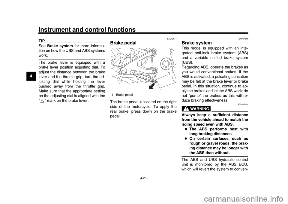
EAU12944
Brake pedalThe brake pedal is located on the right
side of the motorcycle. To apply the
rear brake, press down on the brake
pedal.
EAU67041
Brake systemThis model is equipped with an inte-
grated anti-lock brake system (ABS)
and a variable unified brake system
(UBS).
Regarding ABS, operate the brakes as
you would conventional brakes. If the
ABS is activated, a pulsating sensation
may be felt at the brake lever or brake
pedal. In this situation, continue to ap-
ply the brakes and let the ABS work; do
not “pump” the brakes as this will re-
duce braking effectiveness.
WARNING
EWA16051
Always keep a sufficient distance
from the vehicle ahead to match the
riding speed even with ABS.
The ABS performs best with
long braking distances.
On certain surfaces, such as
rough or gravel roads, the brak-
ing distance may be longer withthe ABS than without.
The ABS and UBS hydraulic control
unit is monitored by the ABS ECU,
which will revert the system to conven-
1. Brake pedal
1
BX4-9-E2.book 28 ページ 2018年9月6日 木曜日 午後4時39分
Page 49 of 124

Instrument and control functions
4-29
1
2
345
6
7
8
9
10
11
12
tional braking if a malfunction occurs.
TIP
The ABS performs a self-diagno-
sis test when the vehicle is started
and reaches a speed of 10 km/h (6
mi/h). During this test, a “clicking”
noise may be audible from the hy-
draulic control unit, and a vibration
may be felt at the bake lever or
pedal, but this is normal.
This ABS has a test mode which
allows the owner to experience the
pulsation at the brake lever or
brake pedal when the ABS is oper-
ating. However, special tools are
required, so please consult yourYamaha dealer.
NOTICE
ECA20100
Be careful not to damage the wheel
sensor or wheel sensor rotor; other-
wise, improper performance of theABS will result.
Regarding variable UBS, operating the
brake lever will generate corresponding
brake pressure at the front brake and to
a variable degree, the rear brake. Theamount of rear wheel braking force to
be applied by the UBS is based on ve-
hicle attitude and lean angle. However,
operating only the brake pedal will not
generate any brake pressure at the
front brake.
For full braking performance, apply
both the brake lever and brake pedal si-
multaneously.
When both the brake lever and the
brake pedal are applied simultaneous-
ly, the UBS will cont
rol the distribution
of braking force between the two
wheels.
TIP
The UBS does not function until
the vehicle starts moving.
After coming to a stop while apply-
ing the brake lever, the UBS is still
enabled. As further squeezing of
the brake lever will not increase
the braking power of the rear
brake, apply the rear brake should
further braking power be neces-
sary (such as when parking on a
slope).
The UBS disables after the brake
lever is released.
1. Front wheel sensor rotor
2. Front wheel sensor
1. Rear wheel sensor rotor
2. Rear wheel sensor
2
12
1
BX4-9-E2.book 29 ページ 2018年9月6日 木曜日 午後4時39分
Page 58 of 124

Instrument and control functions
4-38
1
2
34
5
6
7
8
9
10
11
12
EAU74242
Adjusting th e shock absorber
assemblyThis model is equipped with adjustable
suspension. The spring preload, re-
bound damping force, fast compres-
sion damping force, and slow
compression damping force can be ad-
justed.NOTICE
ECA10102
To avoid damaging the mechanism,
do not attempt to turn beyond themaximum or minimum settings.
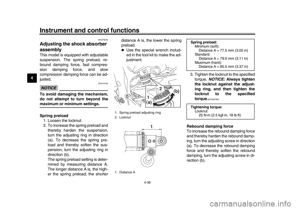
Spring preload
1. Loosen the locknut.
2. To increase the spring preload and thereby harden the suspension,
turn the adjusting ring in direction
(a). To decrease the spring pre-
load and thereby soften the sus-
pension, turn the adjusting ring in
direction (b).
The spring preload setting is deter-
mined by measuring distance A.
The longer distance A is, the high-
er the spring preload; the shorter distance A is, the lower the spring
preload.
Use the special wrench includ-
ed in the tool kit to make the ad-
justment.
3. Tighten the locknut to the specifiedtorque. NOTICE: Always tighten
the locknut against the adjust-
ing ring, and then tighten the
locknut to the specified
torque.
[ECA22760]
Rebound damping force
To increase the rebound damping force
and thereby harden the rebound damp-
ing, turn the adjusting screw in direction
(a). To decrease the rebound damping
force and thereby soften the rebound
damping, turn the adjusting screw in di-
rection (b).
1. Spring preload adjusting ring
2. Locknut
1. Distance A
(a) (b)1
2
1
Spring preload:
Minimum (soft):Distance A = 77.5 mm (3.05 in)
Standard:
Distance A = 79.0 mm (3.11 in)
Maximum (hard): Distance A = 85.5 mm (3.37 in)
Tightening torque: Locknut:25 N·m (2.5 kgf·m, 18 lb·ft)
BX4-9-E2.book 38 ページ 2018年9月6日 木曜日 午後4時39分
Page 60 of 124

Instrument and control functions
4-40
1
2
34
5
6
7
8
9
10
11
12 may be the same.
Although a damping force adjuster
may turn or click beyond the stated
minimum settings, such adjust-
ments are ineffective and maydamage the suspension.WARNING
EWA10222
This shock absorber assembly con-
tains highly pressurized nitrogen
gas. Read and understand the fol-
lowing information before handling
the shock absorber assembly.
Do not tamper with or attempt to
open the cylinder assembly.
Do not subject the shock ab-
sorber assembly to an open
flame or other high heat source.
This may cause the unit to ex-
plode due to excessive gas
pressure.
Do not deform or damage the
cylinder in any way. Cylinder
damage will result in poor
damping performance.
Do not dispose of a damaged or
worn-out shock absorber as-
sembly yourself. Take the shock absorber assembly to a Yamaha
dealer for any service.
EAU67050
EXUP systemThis model is equipped with Yamaha’s
EXUP (EXhaust Ultimate Power valve)
system. This system boosts engine
power by means of a valve that controls
exhaust flow within the exhaust cham-
ber.NOTICE
ECA15611
The EXUP system has been set and
extensively tested at the Yamaha
factory. Changing these settings
without sufficient technical knowl-
edge may result in poor perfor-mance of or damage to the engine.
BX4-9-E2.book 40 ページ 2018年9月6日 木曜日 午後4時39分
Page 67 of 124

6-1
1
2
3
4
567
8
9
10
11
12
Operation and important riding points
EAU15952
Read the Owner’s Manual carefully to
become familiar with all controls. If
there is a control or function you do not
understand, ask your Yamaha dealer.
WARNING
EWA10272
Failure to familiarize yourself with
the controls can lead to loss of con-
trol, which could cause an accidentor injury.
EAU73461
TIPThis model is equipped with:
an inertial measurement unit (IMU)
that will stop the engine in case of
turnover. In this case, turn the
main switch off (and then back on)
before attempting to restart the en-
gine. Failing to do so will prevent
the engine from starting even
though the engine will crank when
the start switch is pushed.
an engine auto-stop system. The
engine stops automatically if left
idling for 20 minutes. In this case,
simply push the start switch to re-start the engine.
EAU79303
Starting the engineIn order for the ignition circuit cut-off
system (page 4-42) to enable starting,
one of the following conditions must be
met:
The transmission is in the neutral
position.
The transmission is in gear with
the clutch lever pulled and the sid-
estand up.
To start the engine
1. Insert the key into the main switch.
2. Set the Stop/Run/Start switch to “”.
3. Turn the main switch (key) to “ON”.
4. Confirm the following warning lights and indicator lights perform a
self-check.
Engine trouble warning light
Oil pressure and coolant tem-
perature warning light
ABS warning light
Fuel level warning light
Auxiliary system warning light
Shift indicator light
Stability control indicator light
BX4-9-E2.book 1 ページ 2018年9月6日 木曜日 午後4時39分