battery YAMAHA YZF-R1 2019 Owners Manual
[x] Cancel search | Manufacturer: YAMAHA, Model Year: 2019, Model line: YZF-R1, Model: YAMAHA YZF-R1 2019Pages: 124, PDF Size: 9.58 MB
Page 7 of 124

Table of contents
Checking and lubricating the brake and clutch levers ............. 7-29
Checking and lubricating the sidestand................................... 7-30
Lubricating the swingarm pivots ... 7-30
Checking the front fork ................. 7-30
Checking the steering . .................. 7-31
Checking the wheel bearings ....... 7-31
Battery .......................................... 7-32
Replacing the fuses ...................... 7-33
Vehicle lights ................................ 7-35
Supporting the motor cycle............ 7-36
Troubleshooting............................ 7-36
Troubleshooting charts ................. 7-38
Motorcycle care and storage .......... 8-1
Matte color caution ......................... 8-1
Care................................................ 8-1
Storage ........................................... 8-4
Specifications .................................. 9-1
Consumer information .................. 10-1
Identification numbers .................. 10-1
Diagnostic connector ... ................. 10-2
Vehicle data recordin g.................. 10-2
Index ............................................... 11-1
BX4-9-E2.book 2 ページ 2018年9月6日 木曜日 午後4時39分
Page 14 of 124

Description
2-2
12
3
4
5
6
7
8
9
10
11
12
EAU10421
Right view
4
3
567
2
1
8,9,10
1. Battery (page 7-32)
2. Front brake fluid reservoir (page 7-24)
3. Document storage space (page 4-35)
4. Coolant reservoir cap (page 7-16)
5. Engine oil filler cap (page 7-12)
6. Brake pedal (page 4-28)
7. Rear brake fluid reservoir (page 7-24)
8. Fast compression damping force adjuster (page 4-36) 9. Slow compression dampi
ng force adjuster (page 4-38)
10.Rebound damping forc e adjuster (page 4-38)
BX4-9-E2.book 2 ページ 2018年9月6日 木曜日 午後4時39分
Page 22 of 124

Instrument and control functions
4-2
1
2
34
5
6
7
8
9
10
11
12
EAU10474
Main switch/steering lockThe main switch/steering lock controls
the ignition and lighting systems, and is
used to lock the steering. The various
positions are described below.TIPBe sure to use the standard key (black
bow) for regular use of the vehicle. To
minimize the risk of losing the code
re-registering key (red bow), keep it in a
safe place and only use it for codere-registering.
EAU85040
ON
All electrical circui ts are supplied with
power and the vehicle lights are turned on. The engine can be started. The key
cannot be removed.
TIP
To prevent battery discharge, do
not leave the key in the on position
without the engine running.
The headlight comes on automati-cally when the engine is started.
EAU10662
OFF
All electrical systems are off. The key
can be removed.
WARNING
EWA10062
Never turn the key to “OFF” or
“LOCK” while the vehicle is moving.
Otherwise the electrical systems will
be switched off, which may result inloss of control or an accident.
EAU1068B
LOCK
The steering is lock
ed and all electrical
systems are off. The key can be re-
moved. To lock the steering
1. Turn the handlebars all the way to
the left.
2. With the key in the “OFF” position, push the key in and turn it to
“LOCK”.
3. Remove the key.TIPIf the steering will not lock, try turningthe handlebars back to the right slightly.
P
ON
OFF
LOCK
1. Push.
2. Turn.12
BX4-9-E2.book 2 ページ 2018年9月6日 木曜日 午後4時39分
Page 23 of 124

Instrument and control functions
4-3
1
2
345
6
7
8
9
10
11
12
To unlock the steering
From the “LOCK” position, push the
key in and turn it to “OFF”.
EAU65680
(Parking)
The hazard lights can be turned on, but
all other electrical systems are off. The
key can be removed.
The steering must be locked before the
key can be turned to “ ”.NOTICE
ECA22330
Using the hazard lights for an ex-
tended length of time may cause thebattery to discharge.
EAU66055
Handlebar switchesLeft
Right
1. Push.
2. Turn.12
1. Pass/LAP switch “ /LAP”
2. Dimmer switch “ / ”
3. Hazard switch “ ”
4. Horn switch “ ”
5. Turn signal switch “ / ”
12543
1. Mode switch “MODE”
2. Up button
3. Center button
4. Down button
1. Stop/Run/Start switch “ / / ”
2. Wheel switch “ ”1
2
4 31
2
BX4-9-E2.book 3 ページ 2018年9月6日 木曜日 午後4時39分
Page 68 of 124

Operation and important riding points
6-2
1
2
3
4
56
7
8
9
10
11
12
Immobilizer system indicator
light
TIP
The oil pressure and coolant tem-
perature warning light will come
on, go off briefly, and then remain
on until the engine is started.
The ABS warning light will remainon until the vehicle starts moving.
NOTICE
ECA24110
If a warning or indicator light does
not work as described above, have aYamaha dealer check the vehicle.
5. Shift the transmission into the neu- tral position (or hold the clutch le-
ver pulled with the sidestand up).
6. Push the start switch, and release it when the engine starts.
If the engine does not start within 5
seconds of pressing the start
switch, wait 10 seconds before
pressing the switch again to allow
battery voltage to restore.
NOTICE
ECA11043
For maximum engine life, never ac-
celerate hard when the engine iscold!
EAU67082
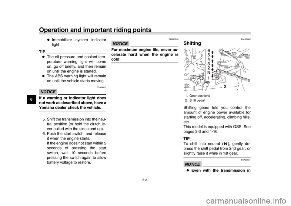
ShiftingShifting gears lets you control the
amount of engine power available for
starting off, accelerating, climbing hills,
etc.
This model is equipped with QSS. See
pages 3-3 and 4-16.TIPTo shift into neutral ( ), gently de-
press the shift pedal from 2nd gear, orslightly raise it while in 1st gear.NOTICE
ECA22521
Even with the transmission in
1. Gear positions
2. Shift pedal
1 2 3 4
5 6
N
1
2
BX4-9-E2.book 2 ページ 2018年9月6日 木曜日 午後4時39分
Page 102 of 124

Periodic maintenance and adjustment
7-32
1
2
3
4
5
67
8
9
10
11
12
EAU68231
BatteryNOTICE
ECA22960
Use only the specified genuine
YAMAHA battery. Using a different
battery may cause the IMU to fail andthe engine to stall.
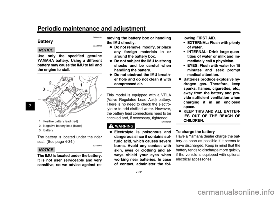
The battery is located under the rider
seat. (See page 4-34.)NOTICE
ECA22970
The IMU is located under the battery.
It is not user serviceable and very
sensitive, so we advise against re- moving the battery box or handling
the IMU directly.
Do not remove, modify, or place
any foreign materials in or
around the battery box.
Do not subject the IMU to strong
shocks and be careful when
handling the battery.
Do not obstruct the IMU breath-
er hole and do not clean it withcompressed air.
This model is equipped with a VRLA
(Valve Regulated Lead Acid) battery.
There is no need to check the electro-
lyte or to add distilled water. However,
the battery lead connections need to be
checked and, if necessary, tightened.WARNING
EWA10761
Electrolyte is poisonous and
dangerous since it contains sul-
furic acid, which causes severe
burns. Avoid any contact with
skin, eyes or clothing and al-
ways shield your eyes when
working near batteries. In case
of contact, administer the fol- lowing FIRST AID.
EXTERNAL: Flush with plenty
of water.
INTERNAL: Drink large quan- tities of water or milk and im-
mediately call a physician.
EYES: Flush with water for 15 minutes and seek prompt
medical attention.
Batteries produce explosive hy-
drogen gas. Therefore, keep
sparks, flames, cigarettes, etc.,
away from the battery and pro-
vide sufficient ventilation when
charging it in an enclosed
space.
KEEP THIS AND ALL BATTER-
IES OUT OF THE REACH OFCHILDREN.
To charge the battery
Have a Yamaha dealer charge the bat-
tery as soon as possible if it seems to
have discharged. Keep in mind that the
battery tends to discharge more quickly
if the vehicle is equipped with optional
electrical accessories.
1. Positive battery lead (red)
2. Negative battery lead (black)
3. Battery
1
2
3
BX4-9-E2.book 32 ページ 2018年9月6日 木曜日 午後4時39分
Page 103 of 124

Periodic maintenance and adjustment7-33
1
2
3
4
5
678
9
10
11
12
NOTICE
ECA16522
To charge a VRLA (Valve Regulated
Lead Acid) battery, a special (con-
stant-voltage) battery charger is re-
quired. Using a conventional batterycharger will damage the battery.
To store the battery 1. If the vehicle will not be used for more than one month, remove the
battery, fully charge it, and then
place it in a cool, dry place.
NOTICE: When removing the
battery, be sure to turn the main
switch off, then disconnect the
negative lead before discon-
necting the positive lead.
[ECA16304]
2. If the battery will be stored for more than two months, check it at least
once a month and fully charge it if
necessary.
3. Fully charge the battery before in- stallation. NOTICE: When install-
ing the battery, be sure to turn
the main switch off, then con-
nect the positive lead before
connecting the negative lead.
[ECA16842]
4. After installation, make sure that
the battery leads are properly con-
nected to the battery terminals.NOTICE
ECA16531
Always keep the battery charged.
Storing a discharged battery cancause permanent battery damage.
EAU66592
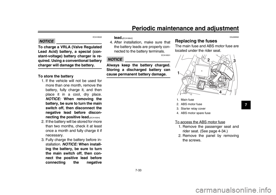
Replacing the fusesThe main fuse and ABS motor fuse are
located under the rider seat.
To access the ABS motor fuse1. Remove the passenger seat andrider seat. (See page 4-34.)
2. Remove the panel by removing the screws.1. Main fuse
2. ABS motor fuse
3. Starter relay cover
4. ABS motor spare fuse1 2
4
3
BX4-9-E2.book 33 ページ 2018年9月6日 木曜日 午後4時39分
Page 108 of 124

Periodic maintenance and adjustment
7-38
1
2
3
4
5
67
8
9
10
11
12
EAU42505
Troubleshooting chartsStarting problems or poor engine performance
Check the fuel level in
the fuel tank.1. Fuel
There is enough fuel.
There is no fuel.
Check the battery.
Supply fuel.
The engine does not start.
Check the battery.
Remove the spark plugs
and check the electrodes.3. Ignition
Wipe off with a dry cloth and correct the
spark plug gaps, or replace the spark plugs.
Have a Yamaha dealer check the vehicle.
Operate the electric starter.4. Compression
There is compression.
There is no compression.
The engine does not start.
Have a Yamaha dealer check the vehicle.Have a Yamaha dealer check the vehicle.
The engine does not start.
Check the compression.
Operate the electric starter.2. Battery
The engine turns over
quickly.
The engine turns over
slowly.
The engine does not start.
Check the ignition.
The battery is good.Check the battery lead connections,
and have a Yamaha dealer charge
the battery if necessary.
DryWet
Operate the electric starter.
BX4-9-E2.book 38 ページ 2018年9月6日 木曜日 午後4時39分
Page 114 of 124

Motorcycle care and storage
8-5
1
2
3
4
5
6
78
9
10
11
12 the tires from becoming degraded
in one spot.
9. Cover the muffler outlet with a plastic bag to prevent moisture
from entering it.
10. Remove the battery and fully charge it, or attach a maintenance
charger to keep the battery opti-
mally charged. NOTICE: Confirm
that the battery and its charger
are compatible. Do not charge a
VRLA battery with a convention-
al charger.
[ECA26330]
TIP
If the battery will be removed,
charge it once a month and store it
in a temperate location between
0-30 C (32-90 F).
See page 7-32 for more informa-
tion on charging and storing thebattery.
BX4-9-E2.book 5 ページ 2018年9月6日 木曜日 午後4時39分
Page 116 of 124

Specifications
9-2
1
2
3
4
5
6
7
89
10
11
12
Loading:Maximum load: 187 kg (412 lb)
The vehicle's maximum load is the combined
weight of the rider, passenger, cargo and any
accessories.Unified brake system:Operation: Activated by front brakeFront brake:Type:Hydraulic dual disc brakeRear brake:Type:
Hydraulic single disc brakeFront suspension:Type:Telescopic forkRear suspension:Type:Swingarm (link suspension)Electrical system:System voltage:
12 VBattery:Model:YTZ7S
Voltage, capacity:
12 V, 6.0 Ah (10 HR)Bulb wattage:Headlight:LED
Brake/tail light:
LED Front turn signal light:
LED
Rear turn signal light:
LED
Auxiliary light: LED
License plate light: LED
BX4-9-E2.book 2 ページ 2018年9月6日 木曜日 午後4時39分