Oil filter YAMAHA YZF-R1 2020 Owners Manual
[x] Cancel search | Manufacturer: YAMAHA, Model Year: 2020, Model line: YZF-R1, Model: YAMAHA YZF-R1 2020Pages: 136, PDF Size: 16.15 MB
Page 8 of 136
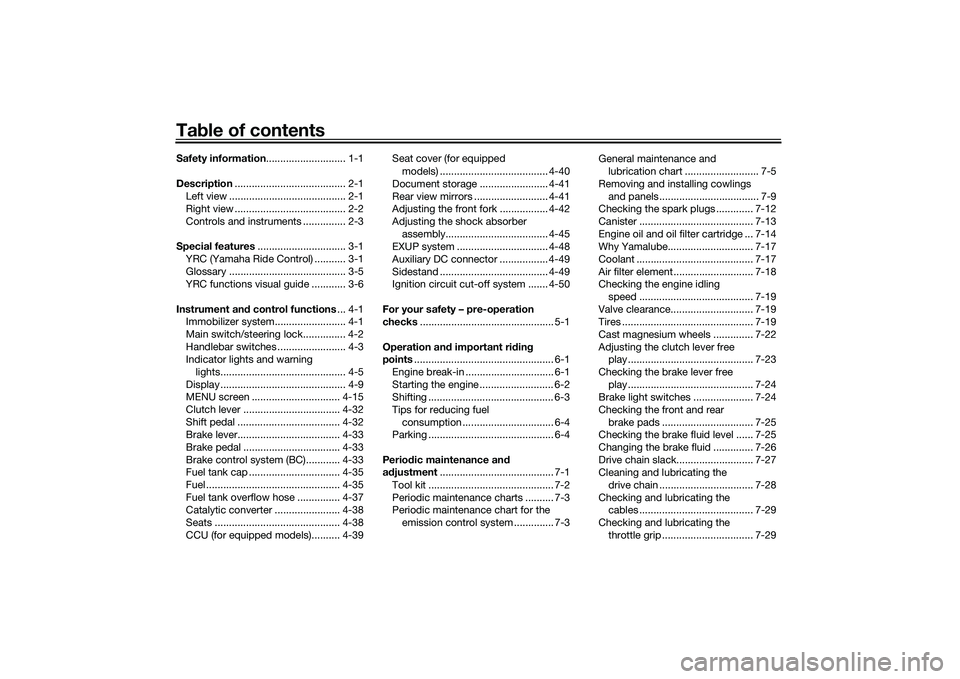
Table of contentsSafety information ............................ 1-1
Description ....................................... 2-1
Left view ......................................... 2-1
Right view ....................................... 2-2
Controls and instruments ............... 2-3
Special features ............................... 3-1
YRC (Yamaha Ride Control) ........... 3-1
Glossary ......................................... 3-5
YRC functions visual guide ............ 3-6
Instrument an d control functions ... 4-1
Immobilizer system......................... 4-1
Main switch/steering lock............... 4-2
Handlebar switches ........................ 4-3
Indicator lights and warning
lights............................................ 4-5
Display ............................................ 4-9
MENU screen ............................... 4-15
Clutch lever .................................. 4-32
Shift pedal .................................... 4-32
Brake lever.................................... 4-33
Brake pedal .................................. 4-33
Brake control system (BC)............ 4-33
Fuel tank cap ................................ 4-35
Fuel ............................................... 4-35
Fuel tank overflow hose ............... 4-37
Catalytic converter ....................... 4-38
Seats ............................................ 4-38
CCU (for equipped models).......... 4-39 Seat cover (for equipped
models) ...................................... 4-40
Document storage ........................ 4-41
Rear view mirrors .......................... 4-41
Adjusting the front fork ................. 4-42
Adjusting the shock absorber assembly.................................... 4-45
EXUP system ................................ 4-48
Auxiliary DC connector ................. 4-49
Sidestand ...................................... 4-49
Ignition circuit cut-off system ....... 4-50
For your safety – pre-operation
checks ............................................... 5-1
Operation an d important ri din g
points ................................................. 6-1
Engine break-in ............................... 6-1
Starting the engine .......................... 6-2
Shifting ............................................ 6-3
Tips for reducing fuel consumption ................................ 6-4
Parking ............................................ 6-4
Perio dic maintenance an d
a d justment ........................................ 7-1
Tool kit ............................................ 7-2
Periodic maintenance charts .......... 7-3
Periodic maintenance chart for the emission control system .............. 7-3 General maintenance and
lubrication chart .......................... 7-5
Removing and installing cowlings and panels ................................... 7-9
Checking the spark plugs ............. 7-12
Canister ........................................ 7-13
Engine oil and oil filter cartridge ... 7-14
Why Yamalube.............................. 7-17
Coolant ......................................... 7-17
Air filter element ............................ 7-18
Checking the engine idling
speed ........................................ 7-19
Valve clearance............................. 7-19
Tires .............................................. 7-19
Cast magnesium wheels .............. 7-22
Adjusting the clutch lever free play ............................................ 7-23
Checking the brake lever free play ............................................ 7-24
Brake light switches ..................... 7-24
Checking the front and rear
brake pads ................................ 7-25
Checking the brake fluid level ...... 7-25
Changing the brake fluid .............. 7-26
Drive chain slack........................... 7-27
Cleaning and lubricating the
drive chain ................................. 7-28
Checking and lubricating the cables ........................................ 7-29
Checking and lubricating the throttle grip ................................ 7-29UB3LE0E0.book Page 1 Tuesday, July 23, 2019 12:05 PM
Page 15 of 136
Description
2-1
2
EAU10411
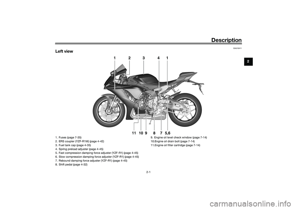
Left view
1
2
3
4
15,6
7
8
9
10
11
1. Fuses (page 7-35)
2. ERS coupler (YZF-R1M) (page 4-42)
3. Fuel tank cap (page 4-35)
4. Spring preload adjuster (page 4-45)
5. Fast compression damping force adjuster (YZF-R1) (page 4-45)
6. Slow compression damping force adjuster (YZF-R1) (page 4-45)
7. Rebound damping force adjuster (YZF-R1) (page 4-45)
8. Shift pedal (page 4-32)9. Engine oil level check window (page 7-14)
10.Engine oil drain bolt (page 7-14)
11.Engine oil filter cartridge (page 7-14)
UB3LE0E0.book Page 1 Tuesday, July 23, 2019 12:05 PM
Page 78 of 136

Operation and important rid ing points
6-1
6
EAU15952
Read the Owner’s Manual carefully to
become familiar with all controls. If
there is a control or function you do not
understand, ask your Yamaha dealer.
WARNING
EWA10272
Failure to familiarize yourself with
the controls can lead to loss of con-
trol, which coul d cause an acci dent
or injury.
EAU16842
En gine break-inThere is never a more important period
in the life of your engine than the period
between 0 and 1600 km (1000 mi). For
this reason, you should read the fol-
lowing material carefully.
Since the engine is brand new, do not
put an excessive load on it for the first
1600 km (1000 mi). The various parts in
the engine wear and polish themselves
to the correct operating clearances.
During this period, prolonged full-throt-
tle operation or any condition that
might result in engine overheating
must be avoided.
EAU17085
0–1000 km (0–600 mi)
Avoid prolonged operation above 7000
r/min. NOTICE: After 1000 km (600
mi) of operation, the en gine oil must
b e chan ged an d the oil filter car-
tri dg e or element replace d.
[ECA10303]
1000–1600 km (600–1000 mi)
Avoid prolonged operation above 8400
r/min. 1600 km (1000 mi) an
d b eyon d
The vehicle can now be operated nor-
mally.
NOTICE
ECA10311
Keep the en gine spee d out of
the tachometer red zone.
If any en gine trou ble shoul d oc-
cur during the en gine break-in
period , imme diately have a
Yamaha dealer check the vehi-
cle.TIPDuring and after the engine break-in
period, the exhaust heat may cause
discoloration of the exhaust pipe, but
this is normal.
UB3LE0E0.book Page 1 Tuesday, July 23, 2019 12:05 PM
Page 88 of 136

Periodic maintenance an d a djustment
7-7
7
20 Si destan d • Check operation.
• Lubricate with lithium-soap-
based grease. √√√√√
21 *Sidestan d switch • Check operation and replace if
necessary. √√√√√√
22 *Front fork • Check operation and for oil leak-
age.
• Replace if necessary. √√√√
23 *Shock a
bsor ber as-
sem bly • Check operation and for oil leak-
age.
• Replace if necessary. √√√√
24 *Rear suspension re-
lay arm an
d con-
nectin g arm
pivotin g points • Check operation.
√√√√
25 En gine oil • Change (warm engine before
draining).
• Check oil level and vehicle for oil leakage. √√√√√√
26 En
gine oil filter car-
tri dge • Replace.
√√√
27 *Coolin g system • Check coolant level and vehicle
for coolant leakage. √√√√√
• Change. Every 3 years
28 *EXUP system • Check operation, cable free play
and pulley position. √√√
29 *Front an
d rear
b rake switches • Check operation.
√√√√√√
NO. ITEM CHECK OR MAINTENANCE JOB
ODOMETER READING
ANNUAL
CHECK
1000 km
(600 mi) 10000 km
(6000 mi) 20000 km
(12000 m
i)30000 km
(18000 mi) 40000 km
(24000 mi)
UB3LE0E0.book Page 7 Tuesday, July 23, 2019 12:05 PM
Page 89 of 136

Periodic maintenance an d a djustment
7-8
7
EAU72811
TIP Air filter
• This model’s air filter uses a disposable oil-coated paper element. This element cannot be cleaned with compressed air, doing so will only damage it.
• The air filter element needs to be replaced more frequently when riding in unusually wet or dusty areas.
Hydraulic brake service
• Regularly check the front and rear brake fluid levels. Replenish if necessary.
• Every two years replace the rear brake master cylinder, the internal components of the front brake master cylinder, the brake calipers, and change the brake fluid.
• Replace the brake hoses every four years or sooner if cracked, damaged, or if any section of the stainless steel brake hose has turned black.30 *Movin
g parts an d
ca bles • Lubricate.
√√√√√
31 *Throttle g rip • Check operation.
• Lubricate throttle grip housing
tube guides. √√√√√
32 *Li
ghts, si gnals an d
switches • Check operation.
• Adjust headlight beam.
√√√√√√
NO. ITEM CHECK OR MAINTENANCE JOB
ODOMETER READING
ANNUAL
CHECK
1000 km
(600 mi) 10000 km
(6000 mi) 20000 km
(12000 mi) 30000 km
(18000 mi) 40000 km
(24000 mi)
UB3LE0E0.book Page 8 Tuesday, July 23, 2019 12:05 PM
Page 95 of 136
Periodic maintenance an d a djustment
7-14
7
EAU66536
En gine oil an d oil filter car-
tri dgeThe engine oil level should be checked
before each ride. In addition, the oil
must be changed and the oil filter car-
tridge replaced at the intervals speci-
fied in the periodic maintenance and
lubrication chart.
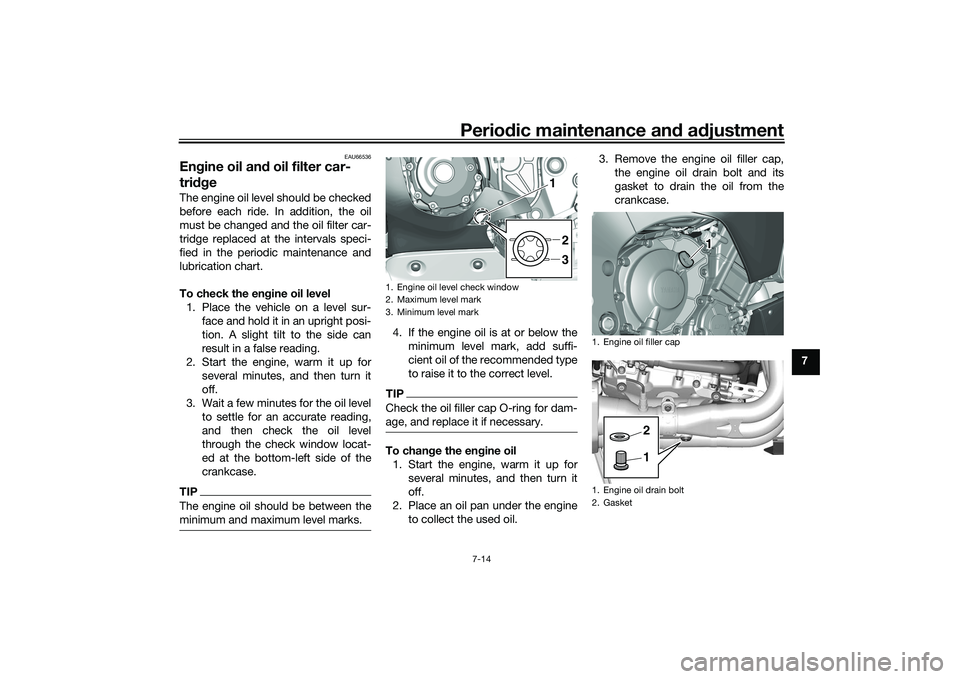
To check the en gine oil level
1. Place the vehicle on a level sur- face and hold it in an upright posi-
tion. A slight tilt to the side can
result in a false reading.
2. Start the engine, warm it up for several minutes, and then turn it
off.
3. Wait a few minutes for the oil level to settle for an accurate reading,
and then check the oil level
through the check window locat-
ed at the bottom-left side of the
crankcase.TIPThe engine oil should be between the
minimum and maximum level marks.
4. If the engine oil is at or below theminimum level mark, add suffi-
cient oil of the recommended type
to raise it to the correct level.TIPCheck the oil filler cap O-ring for dam-
age, and replace it if necessary.To chan ge the en gine oil
1. Start the engine, warm it up for several minutes, and then turn it
off.
2. Place an oil pan under the engine to collect the used oil. 3. Remove the engine oil filler cap,
the engine oil drain bolt and its
gasket to drain the oil from the
crankcase.1. Engine oil level check window
2. Maximum level mark
3. Minimum level mark
2
3
1
1. Engine oil filler cap
1. Engine oil drain bolt
2. Gasket
12
UB3LE0E0.book Page 14 Tuesday, July 23, 2019 12:05 PM
Page 96 of 136

Periodic maintenance an d a djustment
7-15
7 4. Install the engine oil drain bolt and
its new gasket, and then tighten
the bolt to the specified torque.
5. Refill with the specified amount of the recommended engine oil.
TIPBe sure to wipe off spilled oil on any
parts after the engine and exhaust sys-
tem have cooled down.NOTICE
ECA11621
In or der to prevent clutch slip-
pa ge (since the en gine oil also
lu bricates the clutch), do not
mix any chemical additives. Do not use oils with a
diesel speci-
fication of “CD” or oils of a hi gh-
er quality than specifie d. In
a ddition, do not use oils la beled
“ENERGY CONSERVING II” or
hi gher.
Make sure that no forei gn mate-
rial enters the crankcase.
6. Check the oil filler cap O-ring for damage, and replace it if neces-
sary.
7. Install and tighten the oil filler cap. 8. Start the engine, and then let it idle
for several minutes while checking
it for oil leakage. If oil is leaking,
immediately turn the engine off
and check for the cause.
TIPAfter the engine is started, the oil pres-
sure and coolant temperature warning
light should go off if the oil level is suf-
ficient.NOTICE
ECA22490
If the oil pressure an d coolant tem-
perature warnin g lig ht flickers or re-
mains on even if the oil level is
correct, immed iately turn the en gine
off an d have a Yamaha d ealer check
the vehicle.9. Turn the engine off, wait a few minutes for the oil level to settle for
an accurate reading, and then
check the oil level and correct it if
necessary.
Tightenin g torque:
Engine oil drain bolt: 23 N·m (2.3 kgf·m, 17 lb·ft)
Recommen ded en gine oil:
Full synthetic
10W-40, 15W-50
Oil quantity: Oil change:3.90 L (4.12 US qt, 3.43 Imp.qt)
With oil filter removal: 4.10 L (4.33 US qt, 3.61 Imp.qt)
1. Engine oil filler cap
2. O-ring
12
UB3LE0E0.book Page 15 Tuesday, July 23, 2019 12:05 PM
Page 97 of 136

Periodic maintenance an d a djustment
7-16
7
To chan
ge the en gine oil an d replace
the oil filter cartri dge
1. Remove cowling A and panel C. (See page 7-9.)
2. Follow steps 1–3 of the “To change the engine oil” section for
the oil draining procedure.
3. Remove the oil filter cartridge with an oil filter wrench.
TIPAn oil filter wrench is available at a
Yamaha dealer.4. Apply a thin coat of clean engine oil to the O-ring of the new oil filter
cartridge.
TIPMake sure that the O-ring is properly
seated.5. Install the new oil filter cartridgewith an oil filter wrench, and then
tighten it to the specified torque
with a torque wrench. 6. Follow steps 4–9 of the “To
change the engine oil” section for
the oil filling procedure.
7. Install the cowling and panel.
1. Oil filter cartridge
2. Oil filter wrench
1
2
1. O-ring
1
1. Torque wrench
Tightenin g torque:
Oil filter cartridge: 17 N·m (1.7 kgf·m, 13 lb·ft)
1
UB3LE0E0.book Page 16 Tuesday, July 23, 2019 12:05 PM
Page 127 of 136
Specifications
9-1
9
Dimensions:Overall length:2055 mm (80.9 in)
Overall width:
690 mm (27.2 in)
Overall height: 1165 mm (45.9 in)
Seat height: 855 mm (33.7 in) (YZF1000)
860 mm (33.9 in) (YZF1000D)
Wheelbase: 1405 mm (55.3 in)
Ground clearance:
130 mm (5.12 in)
Minimum turning radius: 3.4 m (11.16 ft)Wei ght:Curb weight:
201 kg (443 lb) (YZF1000)
202 kg (445 lb) (YZF1000D)Engine:Combustion cycle:
4-stroke
Cooling system: Liquid cooled
Valve train:
DOHC
Cylinder arrangement: Inline
Number of cylinders: 4-cylinder
Displacement:
998 cm³ Bore
× stroke:
79.0 × 50.9 mm (3.11 × 2.00 in)
Starting system: Electric starter
Engine oil:Recommended brand:
Type:
Full synthetic
SAE viscosity grades: 10W-40, 15W-50
Recommended engine oil grade: API service SG type or higher, JASO
standard MA
Engine oil quantity: Oil change:3.90 L (4.12 US qt, 3.43 Imp.qt)
With oil filter removal: 4.10 L (4.33 US qt, 3.61 Imp.qt)Coolant quantity:Coolant reservoir (up to the maximum level
mark):
0.25 L (0.26 US qt, 0.22 Imp.qt)
Radiator (including all routes): 2.25 L (2.38 US qt, 1.98 Imp.qt)Fuel:Recommended fuel:
Unleaded gasoline (E10 acceptable)
Octane number (RON): 95 Fuel tank capacity:
17 L (4.5 US gal, 3.7 Imp.gal)
Fuel reserve amount: 3.0 L (0.79 US gal, 0.66 Imp.gal)
Fuel injection:Throttle body:ID mark:
B3L1 00Drivetrain:Gear ratio:
1st: 2.600 (39/15)
2nd: 2.176 (37/17)
3rd:
1.842 (35/19)
4th: 1.579 (30/19)
5th: 1.381 (29/21)
6th:
1.250 (30/24)Front tire:Type:Tubeless
Size:
120/70ZR17M/C (58W)
Manufacturer/model: BRIDGESTONE/BATTLAX RACING
STREET RS11FRear tire:Type: Tubeless
UB3LE0E0.book Page 1 Tuesday, July 23, 2019 12:05 PM
Page 132 of 136
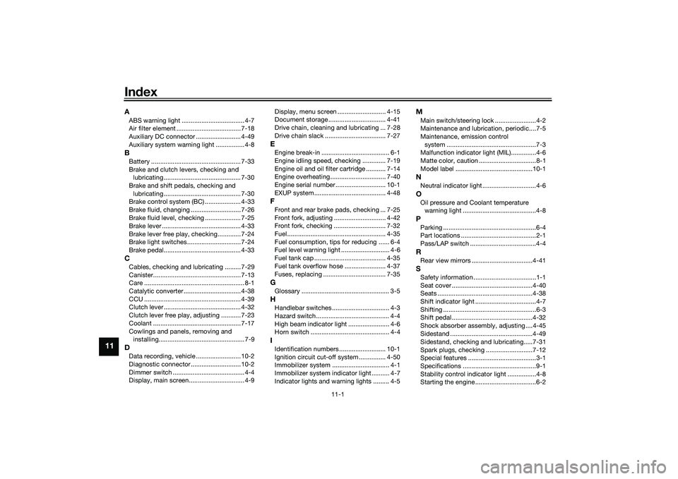
11-1
11
IndexAABS warning light ................................... 4-7
Air filter element .................................... 7-18
Auxiliary DC connector ......................... 4-49
Auxiliary system warning light ................ 4-8BBattery .................................................. 7-33
Brake and clutch levers, checking and
lubricating ........................................... 7-30
Brake and shift pedals, checking and lubricating ........................................... 7-30
Brake control system (BC) .................... 4-33
Brake fluid, changing ............................ 7-26
Brake fluid level, checking .................... 7-25
Brake lever ............................................ 4-33
Brake lever free play, checking............. 7-24
Brake light switches.............................. 7-24
Brake pedal........................................... 4-33CCables, checking and lubricating ......... 7-29
Canister................................................. 7-13
Care ........................................................ 8-1
Catalytic converter ................................ 4-38
CCU ...................................................... 4-39
Clutch lever ........................................... 4-32
Clutch lever free play, adjusting ........... 7-23
Coolant ................................................. 7-17
Cowlings and panels, removing and installing................................................ 7-9DData recording, vehicle ......................... 10-2
Diagnostic connector............................ 10-2
Dimmer switch ........................................ 4-4
Display, main screen............................... 4-9 Display, menu screen ........................... 4-15
Document storage ................................ 4-41
Drive chain, cleaning and lubricating ... 7-28
Drive chain slack .................................. 7-27
EEngine break-in ...................................... 6-1
Engine idling speed, checking ............. 7-19
Engine oil and oil filter
cartridge ........... 7-14
Engine overheating ............................... 7-40
Engine serial number ............................ 10-1
EXUP system........................................ 4-48FFront and rear brake pads, checking ... 7-25
Front fork, adjusting ............................. 4-42
Front fork, checking ............................. 7-32
Fuel ....................................................... 4-35
Fuel consumption, tips for reducing ...... 6-4
Fuel level warning light ........................... 4-6
Fuel tank cap ........................................ 4-35
Fuel tank overflow hose ....................... 4-37
Fuses, replacing ................................... 7-35GGlossary ................................................. 3-5HHandlebar switches ................................ 4-3
Hazard switch......................................... 4-4
High beam indicator light ....................... 4-6
Horn switch ............................................ 4-4IIdentification numbers .......................... 10-1
Ignition circuit cut-off system ............... 4-50
Immobilizer system ................................ 4-1
Immobilizer system indicator light .......... 4-7
Indicator lights and warning lights ......... 4-5
MMain switch/steering lock .......................4-2
Maintenance and lubrication, periodic....7-5
Maintenance, emission control
system ..................................................7-3
Malfunction indicator light (MIL)..............4-6
Matte color, caution ................................8-1
Model label ...........................................10-1NNeutral indicator light ..............................4-6OOil pressure and Coolant temperature warning light .........................................4-8PParking ....................................................6-4
Part locations ..........................................2-1
Pass/LAP switch .....................................4-4RRear view mirrors ..................................4-41SSafety information ...................................1-1
Seat cover .............................................4-40
Seats .....................................................4-38
Shift indicator light ..................................4-7
Shifting ....................................................6-3
Shift pedal .............................................4-32
Shock absorber assembly, adjusting ....4-45
Sidestand ..............................................4-49
Sidestand, checking and lubricating.....7-31
Spark plugs, checking ..........................7-12
Special features ......................................3-1
Specifications .........................................9-1
Stability control indicator light ................4-8
Starting the engine ..................................6-2
UB3LE0E0.book Page 1 Tuesday, July 23, 2019 12:05 PM