change wheel YAMAHA YZF-R1 2022 Owners Manual
[x] Cancel search | Manufacturer: YAMAHA, Model Year: 2022, Model line: YZF-R1, Model: YAMAHA YZF-R1 2022Pages: 136, PDF Size: 6.01 MB
Page 19 of 136
Special features
3-2
3
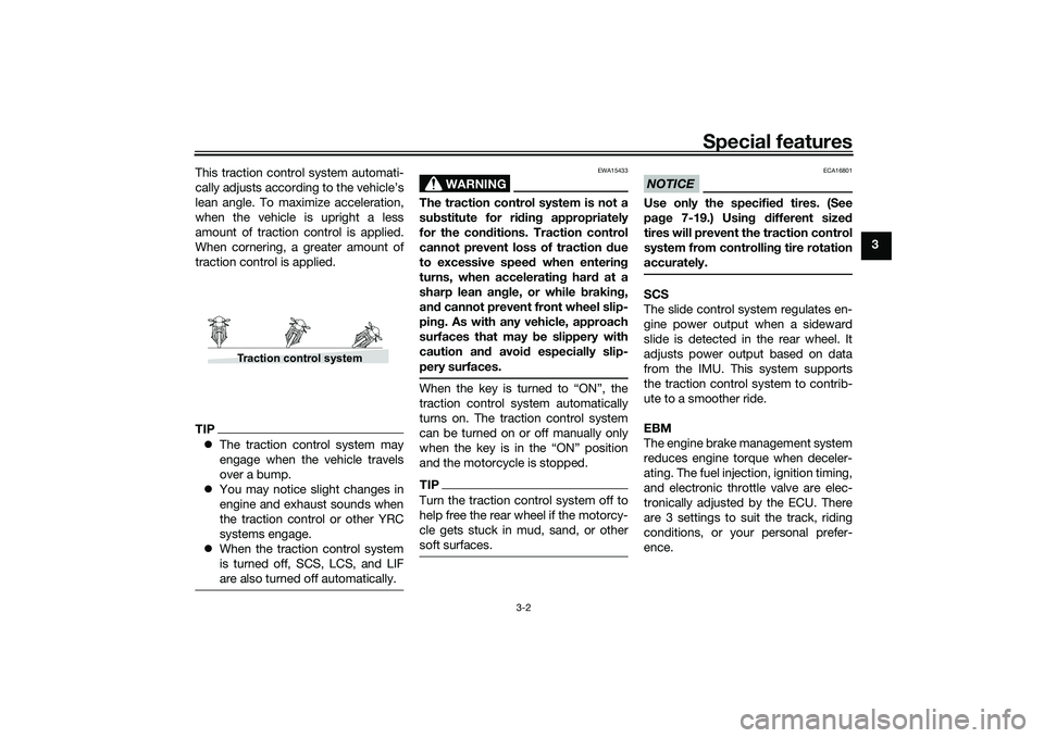
This traction control system automati-
cally adjusts according to the vehicle’s
lean angle. To maximize acceleration,
when the vehicle is upright a less
amount of traction control is applied.
When cornering, a greater amount of
traction control is applied.
TIP
The traction control system may
engage when the vehicle travels
over a bump.
You may notice slight changes in
engine and exhaust sounds when
the traction control or other YRC
systems engage.
When the traction control system
is turned off, SCS, LCS, and LIF
are also turned off automatically.
WARNING
EWA15433
The traction control system is not a
substitute for ri din g appropriately
for the con ditions. Traction control
cannot prevent loss of traction d ue
to excessive spee d when enterin g
turns, when acceleratin g har d at a
sharp lean an gle, or while brakin g,
an d cannot prevent front wheel slip-
pin g. As with any vehicle, approach
surfaces that may be slippery with
caution an d avoi d especially slip-
pery surfaces.When the key is turned to “ON”, the
traction control system automatically
turns on. The traction control system
can be turned on or off manually only
when the key is in the “ON” position
and the motorcycle is stopped.TIPTurn the traction control system off to
help free the rear wheel if the motorcy-
cle gets stuck in mud, sand, or other
soft surfaces.
NOTICE
ECA16801
Use only the specifie d tires. (See
pa ge 7-19.) Usin g different size d
tires will prevent the traction control
system from controllin g tire rotation
accurately.SCS
The slide control system regulates en-
gine power output when a sideward
slide is detected in the rear wheel. It
adjusts power output based on data
from the IMU. This system supports
the traction control system to contrib-
ute to a smoother ride.
EBM
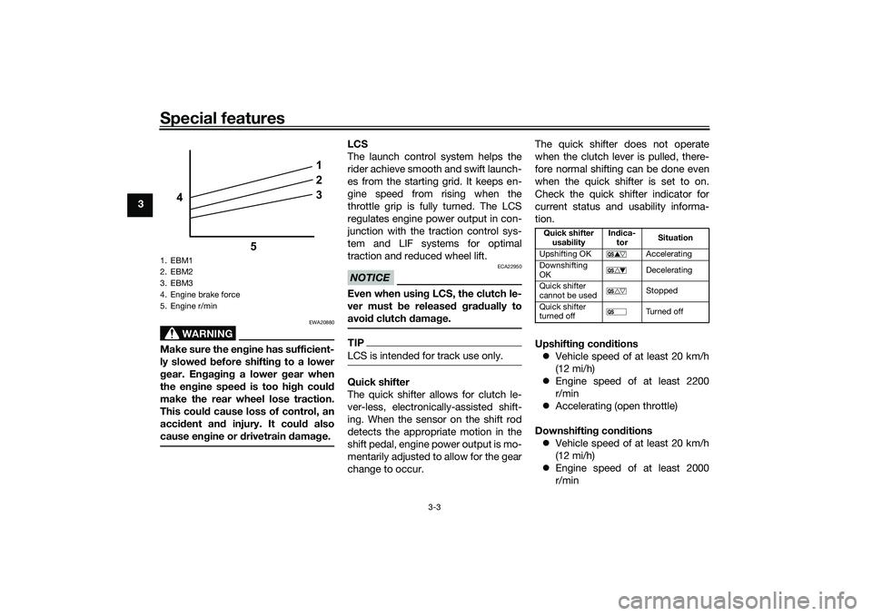
The engine brake management system
reduces engine torque when deceler-
ating. The fuel injection, ignition timing,
and electronic throttle valve are elec-
tronically adjusted by the ECU. There
are 3 settings to suit the track, riding
conditions, or your personal prefer-
ence.
Traction control system
UB3LE1E0.book Page 2 Tuesday, August 10, 2021 2:28 PM
Page 20 of 136
Special features
3-3
3
WARNING
EWA20880
Make sure the engine has sufficient-
ly slowe d b efore shiftin g to a lower
g ear. En gag in g a lower gear when
the en gine speed is too high coul d
make the rear wheel lose traction.
This coul d cause loss of control, an
acci dent an d injury. It coul d also
cause en gine or d rivetrain damag e.
LCS
The launch control system helps the
rider achieve smooth and swift launch-
es from the starting grid. It keeps en-
gine speed from rising when the
throttle grip is fully turned. The LCS
regulates engine power output in con-
junction with the traction control sys-
tem and LIF systems for optimal
traction and reduced wheel lift.NOTICE
ECA22950
Even when usin g LCS, the clutch le-
ver must b e released g ra dually to
avoi d clutch damag e.TIPLCS is intended for track use only.Quick shifter
The quick shifter allows for clutch le-
ver-less, electronically-assisted shift-
ing. When the sensor on the shift rod
detects the appropriate motion in the
shift pedal, engine power output is mo-
mentarily adjusted to allow for the gear
change to occur. The quick shifter does not operate
when the clutch lever is pulled, there-
fore normal shifting can be done even
when the quick shifter is set to on.
Check the quick shifter indicator for
current status and usability informa-
tion.
Upshiftin
g con ditions
Vehicle speed of at least 20 km/h
(12 mi/h)
Engine speed of at least 2200
r/min
Accelerating (open throttle)
Downshiftin g con ditions
Vehicle speed of at least 20 km/h
(12 mi/h)
Engine speed of at least 2000
r/min
1. EBM1
2. EBM2
3. EBM3
4. Engine brake force
5. Engine r/min
1
2
3
4
5
Quick shifter usa bility In
dica-
tor Situation
Upshifting OK Accelerating
Downshifting
OK Decelerating
Quick shifter
cannot be used Stopped
Quick shifter
turned off Tu r n e d o f f
UB3LE1E0.book Page 3 Tuesday, August 10, 2021 2:28 PM
Page 21 of 136
Special features
3-4
3
Engine speed sufficiently away
from red zone
Decelerating and throttle fully-
closed
TIPQS and QS can be individ-
ually set.
Shifting into or out of neutral must
be done using the clutch lever.LIF
The lift control system reduces the rate
at which the front wheel will continue to
rise during extreme acceleration, such
as during starts or out-of-corner exits.
When front-wheel lift is detected, en-
gine power is regulated to slow front-
wheel lift while still providing good ac-
celeration.
BC
The brake control system regulates hy-
draulic brake pressure for the front and
rear wheels when the brakes are ap-
plied and wheel lock is detected. This
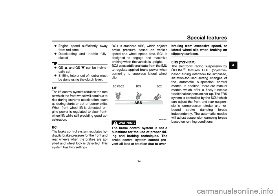
system has two settings. BC1 is standard ABS, which adjusts
brake pressure based on vehicle
speed and wheel speed data. BC1 is
designed to engage and maximize
braking when the vehicle is upright.
BC2 uses additional data from the IMU
to regulate applied brake power when
cornering to suppress lateral wheel
slip.
WARNING
EWA20891
The
brake control system is not a
su bstitute for the use of proper ri d-
in g an d brakin g techniques. The
b rake control system cannot pre-
vent all loss of traction due to over- b
rakin g from excessive spee d, or
lateral wheel slip when brakin g on
slippery surfaces.
ERS (YZF-R1M)
The electronic racing suspension by
ÖHLINS
® features OBTi (objective-
based tuning interface) for simplified,
situation-focused setting changes of
the automatic suspension control
modes. In addition, there are manual
modes which offer a finely-tuneable
traditional suspension set-up. The ERS
system is controlled by the SCU which
can adjust the front and rear suspen-
sion’s compression stroke and re-
bound stroke damping forces
independently. The automatic modes
will adjust suspension damping forces
based on running conditions.
ABS
BC1/BC2 BC2 BC2
UB3LE1E0.book Page 4 Tuesday, August 10, 2021 2:28 PM
Page 28 of 136

Instrument and control functions
4-5
4 push and hold the center button.
The LCS icon will flash and turn
white when the system has been
activated.
The traction control system can
only be turned off from the main
screen. Select TCS with the center
button, then push and hold the up
button until TCS OFF is displayed.
To turn the traction control system
back on, use the down button.
When the traction control system
has been turned off, the SCS,
LCS, and LIF systems are also
turned off for all YRC modes.
See “YRC Setting” on page 4-16
for more information on how to
customize YRC modes and adjust
YRC item setting levels.
EAU66100
Wheel switch “ ”
When the main screen is set to
STREET MODE, use the wheel switch
to scroll and reset the information dis-
play items. When the main screen is set to TRACK
MODE, use the wheel switch to scroll
and reset the information display items
and to activate the lap timer.
When the display has been changed to
the MENU screen, use the wheel
switch to navigate the setting modules
and make setting changes.
Operate the wheel switch as follows.
Rotate up
- rotate the wheel upward to
scroll up/left or increase a setting val-
ue.
Rotate down - rotate the wheel down-
ward to scroll down/right or decrease a
setting value.
Short push - briefly press the switch
inward to make and confirm selec-
tions.
Lon g push - press the switch inward
for one second to reset an information
display item or to access and exit the
MENU screen.
TIP See page 4-9 for more information
on the main screen and its func-
tions.
See page 4-15 for more informa-
tion on the MENU screen and how
to make setting changes.
UB3LE1E0.book Page 5 Tuesday, August 10, 2021 2:28 PM
Page 30 of 136
Instrument and control functions
4-7
4
TIPThe engine is sensitively monitored by
the on-board diagnostic system to de-
tect deterioration or malfunction of the
emission control system. Therefore the
MIL may come on or flash due to vehi-
cle modifications, lack of maintenance,
or excessive/improper use of the mo-
torcycle. To prevent this, observe
these precautions.
Do not attempt to modify the soft-
ware of the engine control unit.
Do not add any electrical acces-
sories that interfere with engine
control.
Do not use aftermarket accesso-
ries or parts such as suspension,
spark plugs, injectors, exhaust
system, etc.
Do not change the drivetrain
specifications (chain, sprockets,
wheels, tires, etc.).
Do not remove or alter the O2 sen-
sor, air induction system, or ex-
haust parts (catalysts or EXUP,
etc.).
Maintain the drive chain properly.
Maintain correct tire pressure.
Maintain proper brake pedal
height to prevent rear brake from
dragging.
Do not operate the vehicle in an
extreme manner. For example, re-
peated or excessive opening and
closing of the throttle, racing,
burnouts, wheelies, extended
half-clutch use, etc.
EAU88342
ABS warnin g li ght “ ”
In normal operation, the ABS warning
light comes on when the vehicle is
turned on, and goes off after traveling
at a speed of 10 km/h (6 mi/h) or high-
er.TIPIf the warning light does not work as
described above, or if the warning light
comes on while riding, the ABS may
not work correctly. Have a Yamaha
dealer check the vehicle as soon as
possible.
WARNING
EWA16043
If the ABS warnin g li ght does not
turn off after reachin g 10 km/h (6
mi/h), or if the warnin g li ght comes
on while ri din g:
Use extra caution to avoi d pos-
si ble wheel lock d uring emer-
g ency brakin g.
Have a Yamaha d ealer check
the vehicle as soon as possi ble.
EAU67434
Shift in dicator li ght “ ”
This indicator light comes on when it is
time to shift to the next higher gear.
The engine speeds at which it comes
on or goes off can be adjusted. (See
page 4-26.)TIPWhen the vehicle is turned on, this light
should come on for a few seconds and
then go off. If the light does not come
on, or if the light remains on, have a
Yamaha dealer check the vehicle.
UB3LE1E0.book Page 7 Tuesday, August 10, 2021 2:28 PM
Page 36 of 136
Instrument and control functions
4-13
4
TIPTurning off the traction control system
will turn off the SCS, LCS, and LIF sys-
tems for all YRC modes.YRC items LCS/QS/LIF/BC
The on/off status of YRC items LCS,
QSS, LIF, and BC is shown here. When
any of these systems are registered
(not set to OFF) for the currently select-
ed YRC mode, its respective icon will
appear.
When LCS is registered for the current-
ly selected YRC mode, its icon will be
grey. To activate the launch control
system, press and hold the center but-
ton until the LCS icon stops flashing
and turns white.TIPLCS, QSS, LIF, and BC system setting
levels can only be adjusted from the
MENU screen.ERS in dicator “ ” (YZF-R1M)
This icon shows the current ERS mo-
de. (See “YRC Setting” on page 4-16
and “ERS” on page 4-20 to change the registered ERS mode or adjust ERS
setting levels.) If the ERS mode disap-
pears from the ERS indicator (the icon
turns blank), stop the vehicle and wait
a few seconds until the mode reap-
pears.
TIP
The suspension will remain fixed
at its most recent settings until
self-reset has completed.
If the ERS indicator does not re-
turn to normal, have a Yamaha
dealer inspect the vehicle.GPS in dicator “ ”
(CCU-equippe d mo dels)
This icon comes on when a GPS unit is
synched with your vehicle.
Lo ggin g in dicator “ ”
(CCU-equippe d mo dels)
This icon comes on when vehicle data
is being recorded via the logging func-
tion.
Clock
The clock uses a 12-hour time system. Lap timer
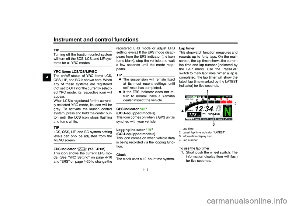
This stopwatch function measures and
records up to forty laps. On the main
screen, the lap timer shows the current
lap time and lap number (indicated by
the LAP mark). Use the Pass/LAP
switch to mark lap times. When a lap is
completed, the lap timer will show the
latest lap time (marked by the LATEST
indicator) for five seconds.
To use the lap timer
1. Short push the wheel switch. The
information display item will flash
for five seconds.
GPS
1. Lap time
2. Latest lap time indicator
Page 38 of 136
Instrument and control functions
4-15
4 Error mo
de warnin g “Err”
When an internal error occurs (e.g.,
communication with a system control-
ler has been cut off), the error mode
warning will appear as follows.
“Err” and “ ” indicates an ECU error.
“Err” and “ ” indicates an SCU error.
“Err” only indicates an ABS ECU error.
TIPDepending on the nature of the error,
the display may not function properly
and YRC settings may be impossible
to change. Additionally, ABS may not
function properly. Use extra care when
braking and have a Yamaha dealer
check the vehicle immediately.
EAU7929B
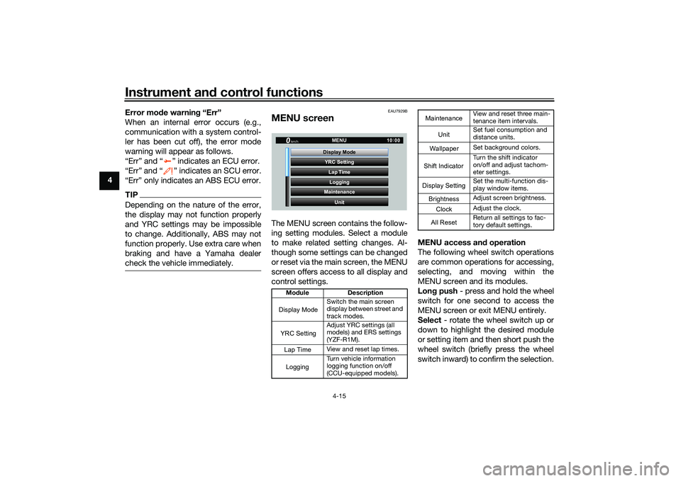
MENU screenThe MENU screen contains the follow-
ing setting modules. Select a module
to make related setting changes. Al-
though some settings can be changed
or reset via the main screen, the MENU
screen offers access to all display and
control settings. MENU access an
d operation
The following wheel switch operations
are common operations for accessing,
selecting, and moving within the
MENU screen and its modules.
Lon g push - press and hold the wheel
switch for one second to access the
MENU screen or exit MENU entirely.
Select - rotate the wheel switch up or
down to highlight the desired module
or setting item and then short push the
wheel switch (briefly press the wheel
switch inward) to confirm the selection.
Mo dule Description
Switch the main screen
display between street and
track modes.
Adjust YRC settings (all
models) and ERS settings
(YZF-R1M).
View and reset lap times.
Turn vehicle information
logging function on/off
(CCU-equipped models).
YRC Setting
Lap TimeLogging
Maintenance
Unit
Display ModeMENU
km/h
GPS
10
:
00
Display ModeYRC SettingLogging
View and reset three main-
tenance item intervals.
Set fuel consumption and
distance units.
Set background colors.
Turn the shift indicator
on/off and adjust tachom-
eter settings.
Set the multi-function dis-
play window items.
Adjust screen brightness.
Adjust the clock.
Return all settings to fac-
tory default settings.
Maintenance
Unit
WallpaperShift IndicatorDisplay SettingBrightnessClockAll Reset
UB3LE1E0.book Page 15 Tuesday, August 10, 2021 2:28 PM
Page 39 of 136
Instrument and control functions
4-16
4
Trian
gle mark - certain setting
screens have an upward pointing trian-
gle mark item. Select the triangle mark
to save setting changes made and exit
that screen.
TIP Should vehicle motion be detect-
ed, the screen will automatically
exit MENU and change to the
main screen.
To ensure that the desired setting
changes are saved, be sure to exit
via the triangle mark. Simply per-
forming a long push and exiting
the MENU screen entirely may not
save setting changes.“Display Mo de”
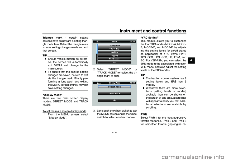
There are two main screen display
modes, STREET MODE and TRACK
MODE.
To set the main screen display mode1. From the MENU screen, select “Display Mode”. 2. Select “STREET MODE” or
“TRACK MODE” (or select the tri-
angle mark to exit).
3. Long push the wheel switch to exit the MENU screen or use the wheel
switch to select another module. “YRC Settin
g”
This module allows you to customize
the four YRC modes MODE-A, MODE-
B, MODE-C, and MODE-D by adjust-
ing the setting levels (or on/off status
as applicable) of YRC items PWR,
TCS, SCS, LCS, QSS, LIF, EBM, and
BC. For YZF-R1M, you can select the
ERS mode to be associated with each
YRC mode, and also adjust the setting
levels of the ERS modes.
TIP The traction control system has 9
setting levels and ERS has 6
modes.
Whenever there are more selec-
tions (setting levels or modes)
available than can be shown on
the screen at one time, a scroll bar
will appear to notify you that addi-
tional selections are available by
scrolling.PWR
Select PWR-1 for the most aggressive
throttle response, PWR-2 and PWR-3
for smoother throttle grip/engine re-
YRC Setting
Lap TimeLogging
Maintenance
Unit
Display ModeMENU
km/h
GPS
10
:
00
km/h
10 :
00
TRACK MODE
STREET MODE
Display Mode
UB3LE1E0.book Page 16 Tuesday, August 10, 2021 2:28 PM
Page 44 of 136
Instrument and control functions
4-21
4
T-2 is preset for track use with
street tires.
R-1 is preset for road use with
street tires.
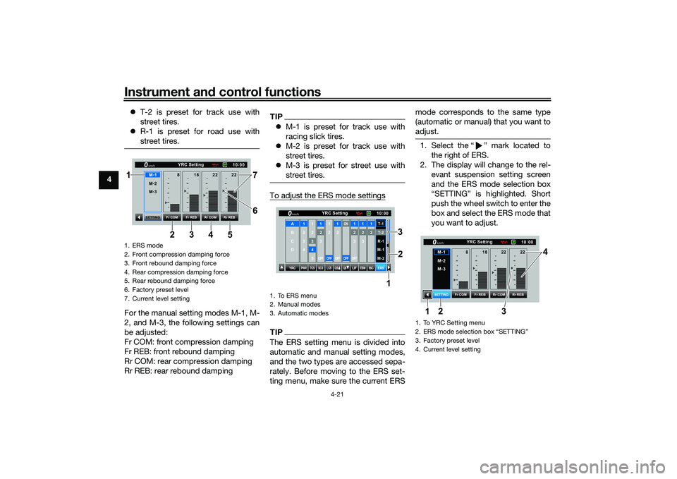
For the manual setting modes M-1, M-
2, and M-3, the following settings can
be adjusted:
Fr COM: front compression damping
Fr REB: front rebound damping
Rr COM: rear compression damping
Rr REB: rear rebound damping
TIPM-1 is preset for track use with
racing slick tires.
M-2 is preset for track use with
street tires.
M-3 is preset for street use with
street tires.To adjust the ERS mode settingsTIPThe ERS setting menu is divided into
automatic and manual setting modes,
and the two types are accessed sepa-
rately. Before moving to the ERS set-
ting menu, make sure the current ERS mode corresponds to the same type
(automatic or manual) that you want to
adjust.
1. Select the Ž mark located to
the right of ERS.
2. The display will change to the rel- evant suspension setting screen
and the ERS mode selection box
push the wheel switch to enter the
box and select the ERS mode that
you want to adjust.
1. ERS mode
2. Front compression damping force
3. Front rebound damping force
4. Rear compression damping force
5. Rear rebound damping force
6. Factory preset level
7. Current level setting
10:
00
YRC Setting
km/hM -
2
M -
3
Fr COM Rr COM
Fr REB Rr REB
SETTING
18
8 22 22
M -
134 7
5 6
2
1
1. To ERS menu
2. Manual modes
3. Automatic modes
YRC
PWR
TCS
SCS
LCSQS
QS
LIFEBM
BC
ERS10
:
00
YRC Setting
km/hA
B
C
D
1
2
3
4
1 2345
12
3OFF
1 2OFF
12OFF
ON
OFF
12
3OFF
12
3
12T-1T-2
R-1
M-1
M-2
1
2
3
1. To YRC Setting menu
2. ERS mode selection box
Page 45 of 136
Instrument and control functions
4-22
4
3. Select the suspension item that
you want to adjust, and then ro-
tate the wheel switch to adjust the
setting level.
TIPAll ERS modes regardless of type are
independent. Offset level setting
changes made in one mode are not
transferred to another mode.4. To adjust other ERS modes of thesame type, repeat from step 1. To
switch types or when finished, se-
lect the Ž mark to return to the
“Lap Time”
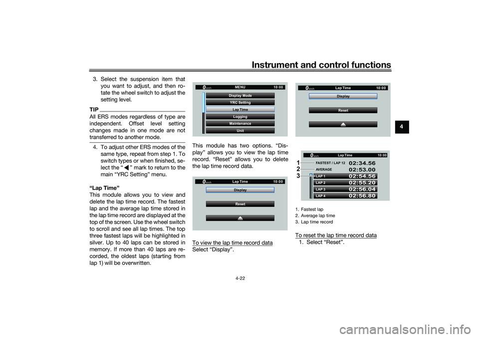
This module allows you to view and
delete the lap time record. The fastest
lap and the average lap time stored in
the lap time record are displayed at the
top of the screen. Use the wheel switch
to scroll and see all lap times. The top
three fastest laps will be highlighted in
silver. Up to 40 laps can be stored in
memory. If more than 40 laps are re-
corded, the oldest laps (starting from
lap 1) will be overwritten. This module has two options. “Dis-
play” allows you to view the lap time
record. “Reset” allows you to delete
the lap time record data.
To view the lap time record data
Select “Display”.
To reset the lap time record data
1. Select “Reset”.
YRC Setting
Lap TimeLogging
Maintenance
Unit
Display ModeMENU
km/h
GPS
10
:
00
km/h
10 :
00
Reset
Display
Lap Time
1. Fastest lap
2. Average lap time
3. Lap time record
km/h
10
:
00
Reset
Display
Lap Time
LAP 1
LAP 2
LAP 3
LAP 4 FASTEST / LAP 12
02:54.56
02:55.20
02:56.04
02:56.80 02:34.56
02:53.00
AVERAGE Lap Timekm/h
GP GPS
10
:
00
1
2
3
UB3LE1E0.book Page 22 Tuesday, August 10, 2021 2:28 PM