warning lights YAMAHA YZF-R1 2022 Owners Manual
[x] Cancel search | Manufacturer: YAMAHA, Model Year: 2022, Model line: YZF-R1, Model: YAMAHA YZF-R1 2022Pages: 136, PDF Size: 6.01 MB
Page 8 of 136
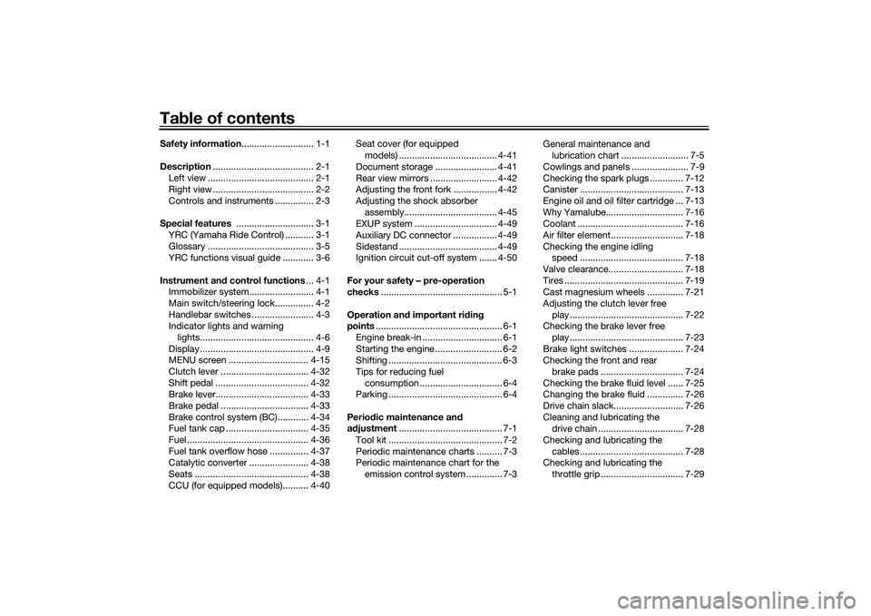
Table of contentsSafety information ............................ 1-1
Description ....................................... 2-1
Left view ......................................... 2-1
Right view ....................................... 2-2
Controls and instruments ............... 2-3
Special features .............................. 3-1
YRC (Yamaha Ride Control) ........... 3-1
Glossary ......................................... 3-5
YRC functions visual guide ............ 3-6
Instrument an d control functions ... 4-1
Immobilizer system......................... 4-1
Main switch/steering lock............... 4-2
Handlebar switches ........................ 4-3
Indicator lights and warning
lights............................................ 4-6
Display ............................................ 4-9
MENU screen ............................... 4-15
Clutch lever .................................. 4-32
Shift pedal .................................... 4-32
Brake lever.................................... 4-33
Brake pedal .................................. 4-33
Brake control system (BC)............ 4-34
Fuel tank cap ................................ 4-35
Fuel ............................................... 4-36
Fuel tank overflow hose ............... 4-37
Catalytic converter ....................... 4-38
Seats ............................................ 4-38
CCU (for equipped models).......... 4-40 Seat cover (for equipped
models) ...................................... 4-41
Document storage ........................ 4-41
Rear view mirrors .......................... 4-42
Adjusting the front fork ................. 4-42
Adjusting the shock absorber assembly.................................... 4-45
EXUP system ................................ 4-49
Auxiliary DC connector ................. 4-49
Sidestand ...................................... 4-49
Ignition circuit cut-off system ....... 4-50
For your safety – pre-operation
checks ............................................... 5-1
Operation an d important ri din g
points ................................................. 6-1
Engine break-in ............................... 6-1
Starting the engine .......................... 6-2
Shifting ............................................ 6-3
Tips for reducing fuel consumption ................................ 6-4
Parking ............................................ 6-4
Perio dic maintenance an d
a d justment ........................................ 7-1
Tool kit ............................................ 7-2
Periodic maintenance charts .......... 7-3
Periodic maintenance chart for the emission control system .............. 7-3 General maintenance and
lubrication chart .......................... 7-5
Cowlings and panels ...................... 7-9
Checking the spark plugs ............. 7-12
Canister ........................................ 7-13
Engine oil and oil filter cartridge ... 7-13
Why Yamalube.............................. 7-16
Coolant ......................................... 7-16
Air filter element ............................ 7-18
Checking the engine idling speed ........................................ 7-18
Valve clearance............................. 7-18
Tires .............................................. 7-19
Cast magnesium wheels .............. 7-21
Adjusting the clutch lever free play ............................................ 7-22
Checking the brake lever free
play ............................................ 7-23
Brake light switches ..................... 7-24
Checking the front and rear brake pads ................................ 7-24
Checking the brake fluid level ...... 7-25
Changing the brake fluid .............. 7-26
Drive chain slack........................... 7-26
Cleaning and lubricating the drive chain ................................. 7-28
Checking and lubricating the cables ........................................ 7-28
Checking and lubricating the
throttle grip ................................ 7-29UB3LE1E0.book Page 1 Tuesday, August 10, 2021 2:28 PM
Page 25 of 136
Instrument and control functions
4-2
4
EAU10474
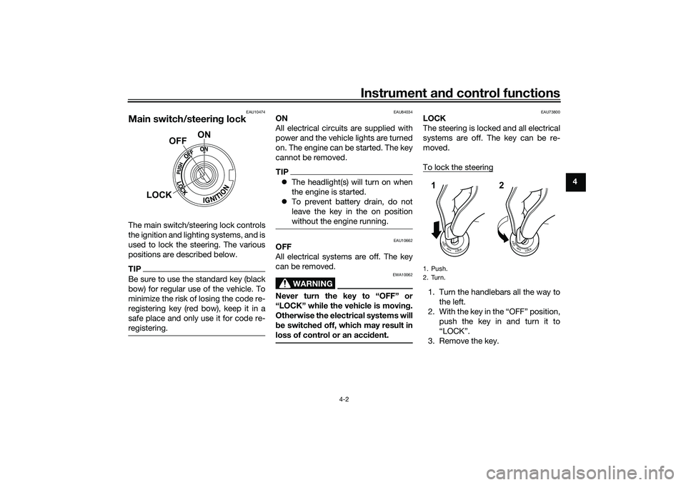
Main switch/steerin g lockThe main switch/steering lock controls
the ignition and lighting systems, and is
used to lock the steering. The various
positions are described below.TIPBe sure to use the standard key (black
bow) for regular use of the vehicle. To
minimize the risk of losing the code re-
registering key (red bow), keep it in a
safe place and only use it for code re-
registering.
EAU84034
ON
All electrical circuits are supplied with
power and the vehicle lights are turned
on. The engine can be started. The key
cannot be removed.TIP The headlight(s) will turn on when
the engine is started.
To prevent battery drain, do not
leave the key in the on position
without the engine running.
EAU10662
OFF
All electrical systems are off. The key
can be removed.
WARNING
EWA10062
Never turn the key to “OFF” or
“LOCK” while the vehicle is movin g.
Otherwise the electrical systems will
b e switched off, which may result in
loss of control or an acci dent.
EAU73800
LOCK
The steering is locked and all electrical
systems are off. The key can be re-
moved.
To lock the steering1. Turn the handlebars all the way to
the left.
2. With the key in the “OFF” position, push the key in and turn it to
“LOCK”.
3. Remove the key.
ON
OFF
LOCK
1. PushK
2. TurnK12
UB3LE1E0.book Page 2 Tuesday, August 10, 2021 2:28 PM
Page 29 of 136
Instrument and control functions
4-6
4
EAU4939R
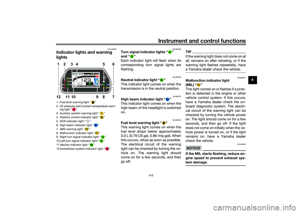
In dicator lig hts and warning
lig hts
EAU88280
Turn si gnal in dicator li ghts “ ”
an d“”
Each indicator light will flash when its
corresponding turn signal lights are
flashing.
EAU88300
Neutral in dicator li ght “ ”
This indicator light comes on when the
transmission is in the neutral position.
EAU88310
Hi gh beam in dicator li ght “ ”
This indicator light comes on when the
high beam of the headlight is switched
on.
EAU88320
Fuel level warning light “ ”
This warning light comes on when the
fuel level drops below approximately
3.0 L (0.79 US gal, 0.66 Imp.gal). When
this occurs, refuel as soon as possible.
The electrical circuit of the warning
light can be checked by turning the ve-
hicle on. The warning light should
come on for a few seconds, and then
go off.
TIPIf the warning light does not come on at
all, remains on after refueling, or if the
warning light flashes repeatedly, have
a Yamaha dealer check the vehicle.
EAU88331
Malfunction in dicator li ght
(MIL) “ ”
This light comes on or flashes if a prob-
lem is detected in the engine or other
vehicle control system. If this occurs,
have a Yamaha dealer check the on-
board diagnostic system. The electri-
cal circuit of the warning light can be
checked by turning the vehicle power
on. The light should come on for a few
seconds, and then go off. If the light
does not come on initially when the ve-
hicle power is turned on, or if the light
remains on, have a Yamaha dealer
check the vehicle.NOTICE
ECA26820
If the MIL starts flashin g, re duce en-
g ine spee d to prevent exhaust sys-
tem damag e.
1. Fuel level warning light “ ”
2. Oil pressure and Coolant temperature warn-
ing light “ ”
3. Auxiliary system warning light “ ”
4. Stability control indicator light “ ”
5. Shift indicator light “ ”
6. High beam indicator light “ ”
7. ABS warning light “ ”
8. Malfunction indicator light “ ”
9. Right turn signal indicator light “ ”
10.Left turn signal indicator light “ ”
11.Neutral indicator light “ ”
12.Immobilizer system indicator light “ ”
ABS
1 2
GPSN
LCSQS
LIF 2
ODO123456 TRIP-1
1234.5
1000 r/min
km
km
km/h
10:
00
MODE-APWR 1TCS 3SCS 2EBM 1T-2
5
12
6
7
9
8
1012
11
3
4
UB3LE1E0.book Page 6 Tuesday, August 10, 2021 2:28 PM
Page 59 of 136

Instrument and control functions
4-36
4
EAU13222
FuelMake sure there is sufficient gasoline in
the tank.
WARNING
EWA10882
Gasoline and gasoline vapors are
extremely flammable. To avoid fires
and explosions and to reduce the
risk of injury when refueling, follow
these instructions.1. Before refueling, turn off the en-gine and be sure that no one is sit-
ting on the vehicle. Never refuel
while smoking, or while in the vi-
cinity of sparks, open flames, or
other sources of ignition such as
the pilot lights of water heaters
and clothes dryers.
2. Do not overfill the fuel tank. When refueling, be sure to insert the
pump nozzle into the fuel tank filler
hole. Stop filling when the fuel
reaches the bottom of the filler
tube. Because fuel expands when
it heats up, heat from the engine or
the sun can cause fuel to spill out
of the fuel tank. 3. Wipe up any spilled fuel immedi-
ately. NOTICE: Immediately
wipe off spilled fuel with a clean,
dry, soft cloth, since fuel may
deteriorate painted surfaces or
plastic parts.
[ECA10072]
4. Be sure to securely close the fuel tank cap.
WARNING
EWA15152
Gasoline is poisonous and can cau-
se injury or death. Handle gasoline
with care. Never siphon gasoline by
mouth. If you should swallow some
gasoline or inhale a lot of gasoline
vapor, or get some gasoline in your
eyes, see your doctor immediately. If gasoline spills on your skin, wash
with soap and water. If gasoline
spills on your clothing, change your
clothes.
EAU86072
Your Yamaha engine was designed to
use unleaded gasoline with a research
octane number of 95 or higher. If en-
gine knocking or pinging occurs, use a
gasoline of a different brand or higher
octane rating.
1. Fuel tank filler tube
2. Maximum fuel level
1
2
Recommended fuel:
Unleaded gasoline (E10 acceptable)
Octane number (RON): 95
Fuel tank capacity: 17 L (4.5 US gal, 3.7 Imp.gal)
Fuel tank reserve:
3.0 L (0.79 US gal, 0.66 Imp.gal)
UB3LE1E0.book Page 36 Tuesday, August 10, 2021 2:28 PM
Page 81 of 136
Operation and important riding points
6-4
6
4. Once the motorcycle has
stopped, the transmission can be
shifted into the neutral position.
The neutral indicator light should
come on and then the clutch lever
can be released.
WARNING
EWA17380
Improper braking can cause
loss of control or traction. Al-
ways use both brakes and apply
them smoothly.
Make sure that the motorcycle
and the engine have sufficiently
slowed before shifting to a low-
er gear. Engaging a lower gear
when the vehicle or engine
speed is too high could make
the rear wheel lose traction or
the engine to over-rev. This
could cause loss of control, an
accident and injury. It could also
cause engine or drive train dam-
age.
EAU16811
Tips for reducing fuel con-
sumptionFuel consumption depends largely on
your riding style. Consider the follow-
ing tips to reduce fuel consumption:
Shift up swiftly, and avoid high en-
gine speeds during acceleration.
Do not rev the engine while shift-
ing down, and avoid high engine
speeds with no load on the en-
gine.
Turn the engine off instead of let-
ting it idle for an extended length
of time (e.g., in traffic jams, at traf-
fic lights or at railroad crossings).
EAU17214
ParkingWhen parking, stop the engine, and
then remove the key from the main
switch.
WARNING
EWA10312
Since the engine and exhaust
system can become very hot,
park in a place where pedestri-
ans or children are not likely to
touch them and be burned.
Do not park on a slope or on soft
ground, otherwise the vehicle
may overturn, increasing the
risk of a fuel leak and fire.
Do not park near grass or other
flammable materials which
might catch fire.
UB3LE1E0.book Page 4 Tuesday, August 10, 2021 2:28 PM
Page 118 of 136

Periodic maintenance and adjustment
7-37
7
TIPThe right headlight comes on
when Pass/LAP switch “ /LAP”
is pushed or the dimmer switch is
set to “ ” (high beam).
The auxiliary lights were designed
to fade out as your R1 goes to
sleep.
EAU67131
Supporting the motorcycleSince this model is not equipped with a
centerstand, use maintenance stands
when removing the front or rear wheel
or when performing other maintenance
that requires the motorcycle to stand
up right.
Check that the motorcycle is in a stable
and level position before starting any
maintenance.
EAU25872
TroubleshootingAlthough Yamaha motorcycles receive
a thorough inspection before shipment
from the factory, trouble may occur
during operation. Any problem in the
fuel, compression, or ignition systems,
for example, can cause poor starting
and loss of power.
The following troubleshooting charts
represent quick and easy procedures
for checking these vital systems your-
self. However, should your motorcycle
require any repair, take it to a Yamaha
dealer, whose skilled technicians have
the necessary tools, experience, and
know-how to service the motorcycle
properly.
Use only genuine Yamaha replace-
ment parts. Imitation parts may look
like Yamaha parts, but they are often
inferior, have a shorter service life and
can lead to expensive repair bills.
WARNING
EWA15142
When checking the fuel system, do
not smoke, and make sure there are
no open flames or sparks in the ar-
ea, including pilot lights from water
1. Maintenance stand (example)
1
UB3LE1E0.book Page 37 Tuesday, August 10, 2021 2:28 PM
Page 132 of 136
11-1
11
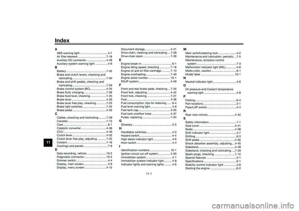
IndexAABS warning light ................................... 4-7
Air filter element .................................... 7-18
Auxiliary DC connector ......................... 4-49
Auxiliary system warning light ................ 4-9BBattery .................................................. 7-32
Brake and clutch levers, checking and lubricating ........................................... 7-30
Brake and shift pedals, checking and lubricating ........................................... 7-29
Brake control system (BC) .................... 4-34
Brake fluid, changing ............................ 7-26
Brake fluid level, checking .................... 7-25
Brake lever ............................................ 4-33
Brake lever free play, checking............. 7-23
Brake light switches.............................. 7-24
Brake pedal........................................... 4-33CCables, checking and lubricating ......... 7-28
Canister................................................. 7-13
Care ........................................................ 8-1
Catalytic converter ................................ 4-38
CCU ...................................................... 4-40
Clutch lever ........................................... 4-32
Clutch lever free play, adjusting ........... 7-22
Coolant ................................................. 7-16
Cowlings and panels .............................. 7-9DData recording, vehicle ......................... 10-2
Diagnostic connector............................ 10-2
Dimmer switch ........................................ 4-4
Display, main screen............................... 4-9
Display, menu screen ........................... 4-15 Document storage ................................ 4-41
Drive chain, cleaning and lubricating ... 7-28
Drive chain slack .................................. 7-26
EEngine break-in ...................................... 6-1
Engine idling speed, checking ............. 7-18
Engine oil and oil filter
cartridge ........... 7-13
Engine overheating ............................... 7-40
Engine serial number ............................ 10-1
EXUP system........................................ 4-49FFront and rear brake pads, checking ... 7-24
Front fork, adjusting ............................. 4-42
Front fork, checking ............................. 7-31
Fuel ....................................................... 4-36
Fuel consumption, tips for reducing ...... 6-4
Fuel level warning light ........................... 4-6
Fuel tank cap ........................................ 4-35
Fuel tank overflow hose ....................... 4-37
Fuses, replacing ................................... 7-34GGlossary ................................................. 3-5HHandlebar switches ................................ 4-3
Hazard switch......................................... 4-4
High beam indicator light ....................... 4-6
Horn switch ............................................ 4-4IIdentification numbers .......................... 10-1
Ignition circuit cut-off system ............... 4-50
Immobilizer system ................................ 4-1
Immobilizer system indicator light .......... 4-8
Indicator lights and warning lights ......... 4-6
MMain switch/steering lock .......................4-2
Maintenance and lubrication, periodic....7-5
Maintenance, emission control system ..................................................7-3
Malfunction indicator light (MIL)..............4-6
Matte color, caution ................................8-1
Model label ...........................................10-1NNeutral indicator light ..............................4-6OOil pressure and Coolant temperature warning light .........................................4-8PParking ....................................................6-4
Part locations ..........................................2-1
Pass/LAP switch .....................................4-4RRear view mirrors ..................................4-42SSafety information ...................................1-1
Seat cover .............................................4-41
Seats .....................................................4-38
Shift indicator light ..................................4-7
Shifting ....................................................6-3
Shift pedal .............................................4-32
Shock absorber assembly, adjusting ....4-45
Sidestand ..............................................4-49
Sidestand, checking and lubricating.....7-30
Spark plugs, checking ..........................7-12
Special features ......................................3-1
Specifications .........................................9-1
Stability control indicator light ................4-8
Starting the engine ..................................6-2
UB3LE1E0.book Page 1 Tuesday, August 10, 2021 2:28 PM